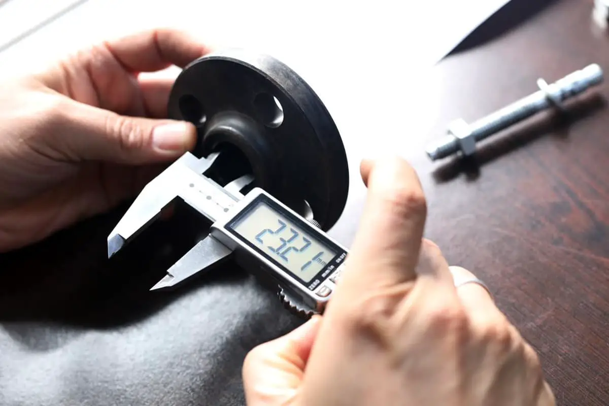
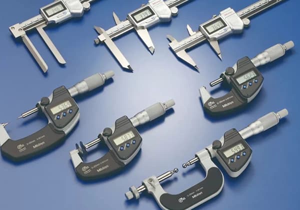
Vernier calipers are frequently employed in the industry as a tool for measuring length.
They can directly measure high-precision workpieces, such as the length, inner diameter, outer diameter, and depth of the workpiece.
Overview of Vernier Calipers
As a widely utilized high-precision measuring tool, vernier calipers consist of a main scale and a vernier that slides on the main scale. Depending on the scale value on the vernier, vernier calipers can be divided into three types: 0.1, 0.05, and 0.02mm.
Reading Method of the Vernier Caliper
Taking an accurate Vernier caliper with a scale value of 0.02mm as an example, the reading method can be divided into three steps:
1) The whole millimeter value is read based on the closest scale on the main ruler to the left of the zero line of the vernier scale.
2) The decimal value is read by multiplying the number of scales aligned on the main ruler to the right of the zero line on the vernier scale by 0.02.
3) The final measurement is obtained by adding up the integer and decimal parts detailed above.
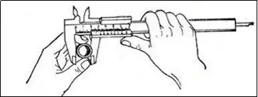
Method of Reading a 0.02mm Vernier Caliper.
As shown in the figure above, the zero line of the vernier scale corresponds to the 64mm mark on the main scale. The ninth line behind the zero line of the vernier scale aligns with a scale line on the main scale.
The ninth line behind the zero line of the vernier scale represents: 0.02×9= 0.18mm;
Therefore, the dimension of the measured workpiece is: 64+0.18=64.18mm.
Instructions for Using a Vernier Caliper
Align the jaws and check whether the vernier zero mark aligns with the main scale’s zero mark. If it aligns, you can proceed with the measurement. If not, you need to note the zero error.
If the vernier’s zero mark is to the right of the zero mark on the scale body, it’s considered a positive zero error. If it’s to the left, it’s a negative zero error (this rule aligns with the convention for number lines, where points to the right of the origin are positive and those to the left are negative).
During measurement, hold the scale body in your right hand and move the vernier with your thumb.
Hold the object to be measured (either its external or internal diameter) in your left hand, positioning it between the external measuring jaws. When the object fits tightly against the jaws, you can read the measurement, as shown in the figure below:
Applications of Vernier Calipers
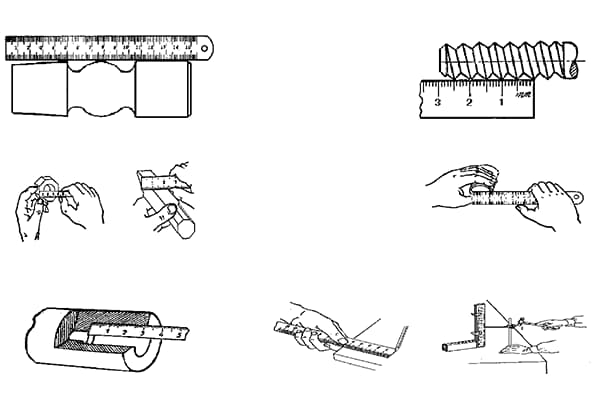
Vernier calipers, as a commonly used measuring tool, can be specifically applied in the following four areas:
1) Measuring the width of workpieces
2) Measuring the external diameter of workpieces
3) Measuring the internal diameter of workpieces
4) Measuring the depth of workpieces
Please refer to the figure below for specific measurement methods for these four areas:
Usage Precautions
The Vernier caliper is a highly precise measuring instrument. Certain care should be taken during its use:
1. Before using, clean both jaws’ measuring surfaces. Close the jaws and check if the zero line on the vernier scale aligns with the main scale’s zero line. If misaligned, adjust the measurement reading according to the original error.
2. When measuring a workpiece, the jaws’ measuring surfaces must be parallel or perpendicular to the surface of the workpiece. Avoid tilting and excessive force to prevent the jaws from deforming or wearing, which could affect measurement accuracy.
3. When reading the calibration, your line of sight should be perpendicular to the scale surface. Otherwise, the measurement value may be inaccurate.
4. When measuring the inner diameter, gently swing the caliper to find the maximum value.
5. After using the Vernier caliper, clean it thoroughly, apply protective oil, and store it flat inside a case to prevent rusting or bending.
The micrometer, also known as a screw gauge, is another precise measuring instrument. The following will explain the principles, structure, and usage methods of the micrometer.
What is a micrometer?
A micrometer, also known as a screw micrometer or vernier caliper, is a tool for measuring length with greater precision than a vernier caliper.
It can measure lengths accurately to 0.01mm, with a measurement range spanning several centimeters.
The structure of a micrometer
Below is a schematic diagram of the structure of a micrometer:
Working Principle of the Micrometer Screw Gauge
The micrometer screw gauge is manufactured based on the principle of helical amplification, that is, when a screw rotates one full turn in the nut, it advances or retreats a distance of one pitch along the direction of the rotation axis.
Thus, a minor distance moved in the axial direction can be represented by readings on the circumference.
The precision micrometer’s screw thread has a pitch of 0.5mm, and the movable scale has 50 subdivided scales. With one complete rotation of the movable scale, the micrometer screw can advance or retreat 0.5mm.
Therefore, each small subdivision rotation equates to the micrometer screw advancing or retreating 0.01mm (0.5/50). It is evident that each small division on the movable scale represents 0.01mm, hence the micrometer can measure accurately to 0.01mm.
Since it can read to the thousandth of a millimeter, it is also known as a thousandths ruler.
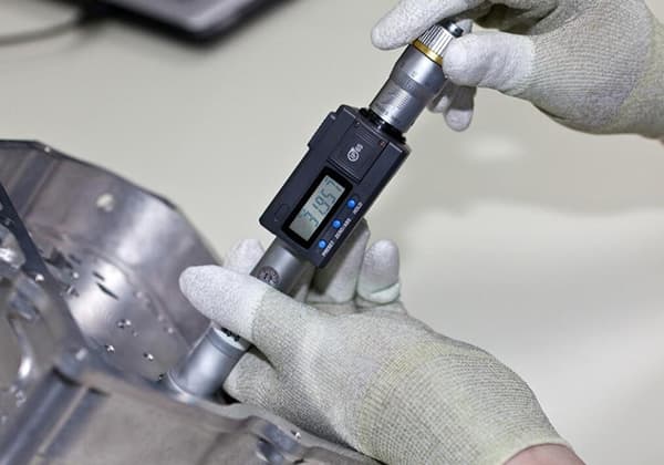
How to Use the Screw Micrometer
When we often help customers connect our data acquisition device with the screw micrometer for high-efficiency measurements, we typically instruct them to adhere to the following points:
1. Prior to use, check the zero point: Slowly rotate the fine-tuning knob D′ to make the measuring rod (F) and the measuring anvil (A) contact until a click sound can be heard. At this point, the zero marking on the movable sleeve should align with the baseline (long horizontal line) on the fixed sleeve, otherwise, a zero error exists.
2. Hold the caliper (C) in your left hand, and with your right hand, turn the coarse adjustment knob (D) so that the gap between the measuring rod (F) and the anvil (A) is slightly larger than the object to be measured. Insert the object, then turn the lock knob (D’) until the object is secured and the ratchet emits a sound. Once the measuring rod is fixed by manipulating the lock knob (G), take the reading.
Reading Method for Micrometer Screw Gauge
1. Firstly, read the fixed scale.
2. Then, read the half scale. If the half-scale line is visible, record it as 0.5mm; if it’s not visible, record it as 0.0mm.
3. Next, read the movable scale (considering estimated readings), recorded as n×0.01mm.
4. The final reading is the sum of the fixed scale, half scale, and movable scale.
Since the reading result of the micrometer screw gauge is precise to the thousandths place in millimeters, it’s also known as a micrometer.
Things to Note with the Micrometer Screw Gauge
1. When measuring, ensure to stop using the knob when the micrometer screw is close to the object being measured. Use the fine-tuning knob instead to prevent excessive pressure. This will ensure accurate measurements and protect the micrometer screw gauge.
2. When reading the scale, pay attention to whether the line representing half a millimeter on the fixed scale is visible.
3. During reading, the thousandths place has an estimated digit that should not be disregarded, even if the zero point of the fixed scale aligns with a certain scale line of the movable scale. The thousandths place should still read as “0”.
4. When the anvil and micrometer screw are closed together, if the zero point of the movable scale doesn’t coincide with the zero point of the fixed scale, a zero error will occur. This should be corrected by subtracting the zero error value from the final length reading.
Proper Use and Maintenance of Micrometer Screw Gauge
• Verify the accuracy of the zero mark;
• Ensure the surface of the workpiece to be measured is cleaned;
• For larger workpieces, use a V-block or flat plate for measurement;
• Clean the measuring rod and anvil before measurement;
• Use a ratchet device when adjusting the thimble;
• Avoid loosening the back cover to prevent altering the zero mark;
• Do not introduce common machine oil between the fixed and the movable sleeve;
• After use, clean and oil the micrometer, store it in its designated case, and keep it in a dry place.