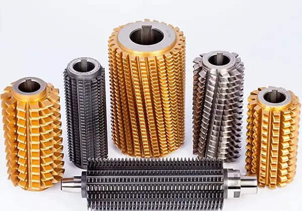
9 Types of Hobs: How Much Do You Know?
What makes hobs so crucial in gear manufacturing? This article explores nine different types of hobs, detailing their unique features and applications in machining. From gear hobs to specialized tooth…
Ever wondered how helical gears are crafted with precision using modern technology? This article delves into the intricate process of machining helical gears using a four-axis CNC machine. It covers everything from simulation verification to actual cutting, offering insights into the tools, software, and techniques that ensure high-quality production. By the end of this piece, you’ll gain a comprehensive understanding of how advancements in CNC technology are revolutionizing gear manufacturing, making complex processes more accessible and efficient.
As an example, let’s consider a typical helical cylindrical gear. Using a four-axis machining center and CAXA software, we will explore the four-axis NC machining method of helical gear through cutting simulation verification and actual cutting on the machine tool using VERICUT.
The processing of spur and helical cylindrical gears is typically achieved through hobbing, gear shaping, or gear grinding. With the advancement of the four-axis machining center, processes that were previously challenging to complete on three-axis machining centers can now be performed on four-axis equipment. In this paper, we will examine the four-axis NC machining method of a typical helical gear.
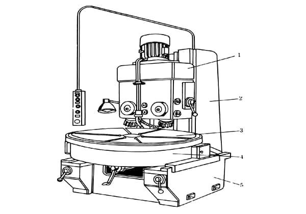
Traditionally, the machining of helical gears was carried out using hobbing machines. With the advancement of NC technology, particularly the development of four-axis linkage technology in machining centers, helical gears can now be machined on NC machine tools.
In this post, we will explore the processing methods of helical gears. Using the CAXA Manufacturing Engineer software developed in China, simulation verification is conducted with the assistance of VERICUT. The processing of both standard and custom helical gears is performed on a four-axis machining center platform.
As shown in Figure 1, the helical gear to be processed has a 20° tooth inclination and 20 teeth, and is made of LY12 material, as listed in Table 1. The challenge of this case is the lack of specialized gear processing equipment on the competition site. Each station is equipped with a four-axis processing center and is required to complete simulation and actual processing, as well as to produce a set of roller die mechanism matched with the helical gear on site. The mechanism must run automatically when powered on and meet high gear matching requirements.
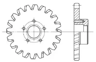
Fig. 1 helical gear
| Tooth profile | Involute |
| Tooth inclination / (°) | 20 / pair of teeth |
| Modulus | 4 |
| Number of teeth / piece | 20 |
| Graduation circle diameter / mm | 80 |
The CAXA Manufacturing Engineer software has a wide range of functions for four-axis and five-axis machining. To process the helical gear, the first step is to draw the gear’s geometry and then generate the tool path.
The following steps are involved in generating the path:

a) Rough machining path

b) Finishing tool path

c) Simulate cutting effect
Fig. 2 conventional helical gear machining tool path and cutting simulation
This process utilizes the five-axis tool path processing function, which is then transformed into a four-axis tool path to be executed on a more common four-axis machine tool. This process is used for one tooth and can be easily applied to other teeth by simply rotating the tool path. This method is highly adaptable, using conventional cutting tools to copy and cut along the curved surface, and can be applied to the processing of helical gears of other sizes.
However, this method has a low processing efficiency and accuracy. The curved surface is produced through tool splitting, making it suitable for single piece trial processing or small-scale production. When processing in batches, its weakness in terms of low efficiency and low precision becomes apparent. Therefore, it is imperative to find a more suitable processing method for batch processing of products.
By using design software, such as the CAXA electronic drawing board, the relevant parameters of the helical gear can be entered into Table 1 to quickly obtain the tooth profile, and then the data can be extracted. The CAD drawing data of the tooth profile can be obtained based on the tooth profile and provided to the tool manufacturer to make custom gear knives.
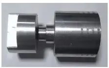
As depicted in Fig. 3, the diameter of the tool handle is 12mm, the length is 70mm, and the cutting edge part is customized according to the tooth profile data. Although custom tools have a higher cost compared to general tools, they offer high processing efficiency, good quality, and overall benefits in batch processing.

a) Pattern

b) Physical object
Fig. 3 customized gear cutter
The analysis of this workpiece shows that it has a short clamping size, making alignment difficult and increasing the processing time. Additionally, when machining the tooth profile, the tool and spindle are close to the four-axis chuck, increasing the risk of interference and making clamping and alignment challenging, making batch processing less convenient.
To improve processing efficiency, a custom fixture is needed, as shown in Fig. 4. Fig. 4a is a movable part that clamps the gear blank through threads, ensuring that the clamping position is fixed each time, thus reducing tool setting time. Fig. 4b shows the fixed part, which is attached to the chuck. The actual fixture is shown in Fig. 4c.

a) Moving parts

b) Fixings
c) Physical object
Fig. 4 custom fixture
(1) To generate the tool path, draw a line with a 20° inclination between the tooth bottom circle and the helical gear. Then, select “Machining → Four Axis Machining → Four Axis Cylindrical Curve Machining. Set the tool and cutting parameters and generate the tool path. Further tool paths can be obtained through path rotation array. The steps for generating the path are shown in Fig. 5.

Fig. 5 generation of tool path
(2) To complete the machining process, generate G code and verify it using VERICUT. Select the tool path, generate the G code, and then import it into the VERICUT software to simulate the trial cutting process (refer to Fig. 6a). After verification, import the code into the machine tool. The actual object obtained through cutting is shown in Fig. 6b.

a) Simulated cutting

b) Physical object
Fig. 6 simulated cutting and machining
Typically, helical gears are machined on specialized hobbing machines and not as often on widely used CNC machining centers. This post explores the machining method of helical gears on a four-axis machining center and provides a preliminary exploration of the four-axis NC machining method for helical gears.
For single piece or small-scale production, profiling processing can be used. For batch processing, it is recommended to use custom tools. This method overcomes the limitation of helical gear processing on specialized equipment and can be applied to more widely used NC equipment currently available.

As the founder of MachineMFG, I have dedicated over a decade of my career to the metalworking industry. My extensive experience has allowed me to become an expert in the fields of sheet metal fabrication, machining, mechanical engineering, and machine tools for metals. I am constantly thinking, reading, and writing about these subjects, constantly striving to stay at the forefront of my field. Let my knowledge and expertise be an asset to your business.