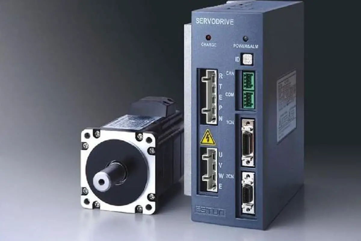
3 Servo Motor Control Modes Explained
Ever wondered how machines achieve precise movements? This blog dives into the fascinating world of servo motor control modes. From pulse to analog control, we'll explore how each method works…
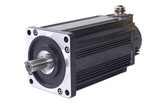
Ever wondered how machines select the perfect motor? This article unveils the fascinating process behind choosing the right servo motor for various mechanical tasks. Dive in to understand the calculations and criteria engineers use to ensure efficiency and precision in machinery.
Given:
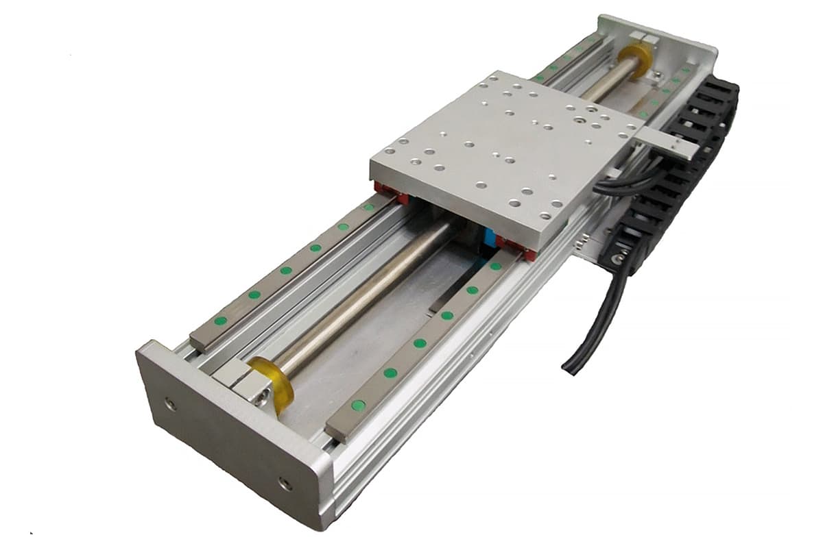
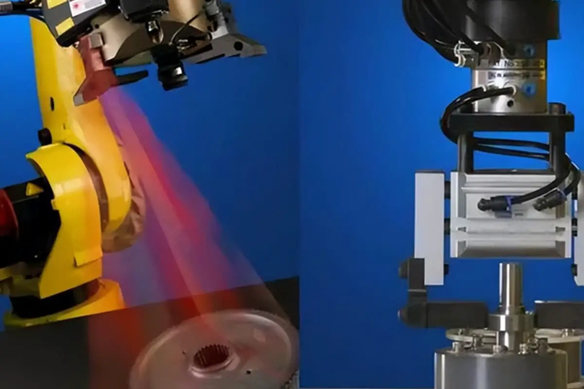
Please select the servo motor and reduction gear, component schematic as follows:
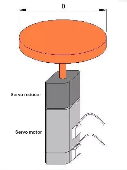
Calculating the moment of inertia for the disc rotation
JL = MD2/8 = 50 * 502 / 8 = 15625 [kg·cm2]
Assuming a gear reduction ratio of 1:R, the load inertia reflected on the servo motor shaft is 15625/R2.
According to the principle that the load inertia should be less than three times the rotor inertia JM of the motor,
if a 400W motor is selected, JM = 0.277 [kg·cm2],
then: 15625 / R2 < 3*0.277, R2 > 18803, R > 137,
the output speed = 3000/137 = 22 [rpm],
which does not meet the requirement.
If a 500W motor is selected, JM = 8.17 [kg·cm2],
then: 15625 / R2 < 3*8.17, R2 > 637, R > 25,
the output speed = 2000/25 = 80 [rpm],
which satisfies the requirement.
This type of transmission has minimal resistance, so torque calculations are ignored.
Given:
Ignoring the weight of each conveyor belt wheel,
What is the minimum power requirement for a motor to drive such a load?
The schematic diagram of the component is as follows:
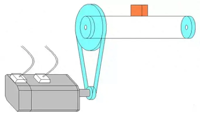
1. Calculating the load inertia reflected on the motor shaft:
JL = M * D2 / 4 / R12
= 50 * 144 / 4 / 100
= 18 [kg·cm2]
According to the principle that load inertia should be less than three times the motor rotor inertia (JM):
JM > 6 [kg·cm2]
2. Calculating the torque required to drive the motor load:
Torque required to overcome friction:
Tf = M * g * µ * (D / 2) / R2 / R1
= 50 * 9.8 * 0.6 * 0.06 / 2 / 10
= 0.882 [N·m]
Torque required for acceleration:
Ta = M * a * (D / 2) / R2 / R1
= 50 * (30 / 60 / 0.2) * 0.06 / 2 / 10
= 0.375 [N·m]
The servo motor’s rated torque should be greater than Tf, and the maximum torque should be greater than Tf + Ta.
3. Calculating the required motor speed:
N = v / (πD) * R1
= 30 / (3.14 * 0.12) * 10
= 796 [rpm]
Given:
Please select the servo motor with the minimum power that meets the load requirements,
The component diagram is as follows:

1. Calculation of Load Inertia Converted to the Motor Shaft
Load inertia of the weight converted to the motor shaft
JW = M * (PB / 2π)²
= 200 * (2 / 6.28)²
= 20.29 [kg·cm²]
The rotational inertia of the screw
JB = MB * DB² / 8
= 40 * 25 / 8
= 125 [kg·cm²]
Total load inertia
JL = JW + JB = 145.29 [kg·cm²]
2. Calculation of Motor Speed
Required motor speed
N = V / PB
= 30 / 0.02
= 1500 [rpm]
3. Calculation of Torque Required to Drive the Motor Load
The torque required to overcome friction
Tf = M * g * µ * PB / 2π / η
= 200 * 9.8 * 0.2 * 0.02 / 2π / 0.9
= 1.387 [N·m]
Torque required when the weight is accelerating
TA1 = M * a * PB / 2π / η
= 200 * (30 / 60 / 0.2) * 0.02 / 2π / 0.9
= 1.769 [N·m]
Torque required when the screw is accelerating
TA2 = JB * α / η
= JB * (N * 2π / 60 / t1) / η
= 0.0125 * (1500 * 6.28 / 60 / 0.2) / 0.9
= 10.903 [N·m]
Total torque required for acceleration
TA = TA1 + TA2 = 12.672 [N·m]
4. Selection of Servo Motor
Rated torque of the servo motor
T > Tf and T > Trms
Maximum torque of the servo motor
Tmax > Tf + TA
Finally, the ECMA-E31820ES motor was selected.

As the founder of MachineMFG, I have dedicated over a decade of my career to the metalworking industry. My extensive experience has allowed me to become an expert in the fields of sheet metal fabrication, machining, mechanical engineering, and machine tools for metals. I am constantly thinking, reading, and writing about these subjects, constantly striving to stay at the forefront of my field. Let my knowledge and expertise be an asset to your business.