Ever wondered how machines achieve precise movements? This blog dives into the fascinating world of servo motor control modes. From pulse to analog control, we’ll explore how each method works and where it’s best applied. Get ready to uncover the secrets behind the precision and efficiency of modern machinery!
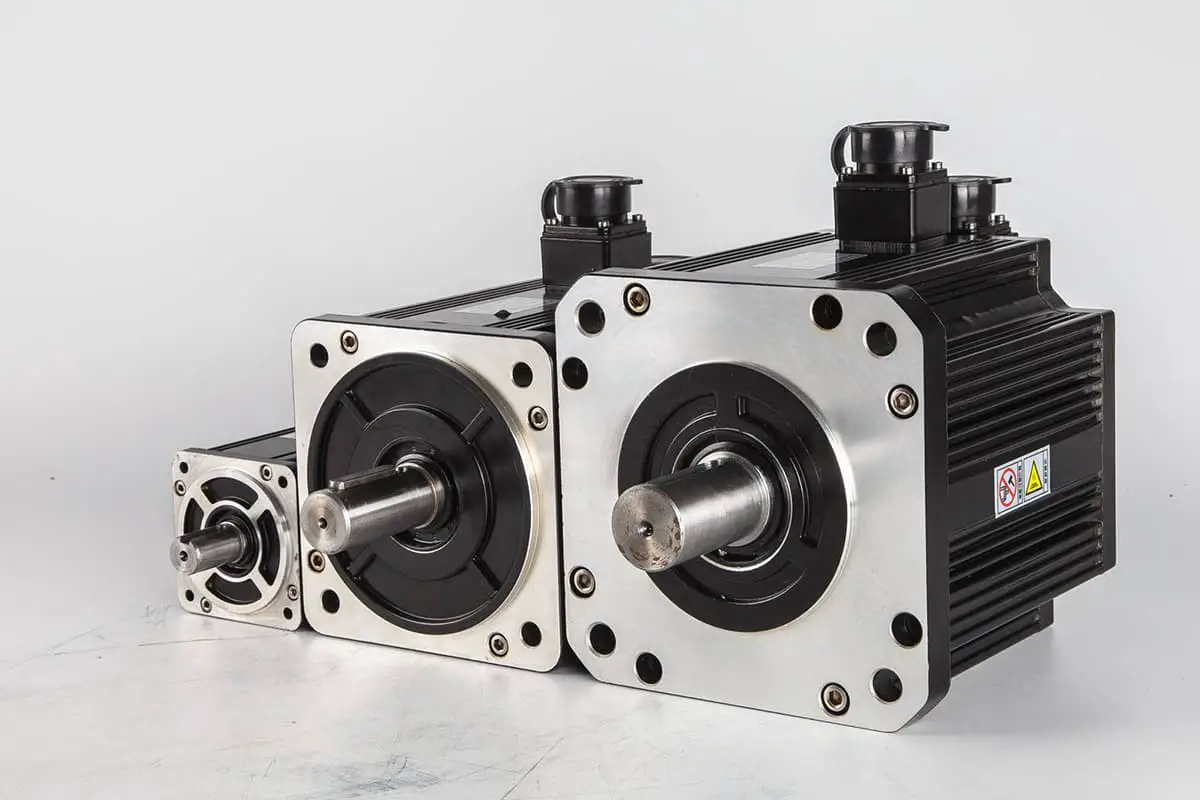
Servo motors are widely used in various applications due to their precision and reliability. One of the most common methods of controlling servo motors, especially in small stand-alone equipment, is through pulse control. This method is straightforward and easy to understand, making it a popular choice for motor positioning.
Basic Control Concept
The pulse control mode operates on two fundamental principles:
Total Pulse Count: This determines the motor’s displacement. The number of pulses sent to the servo motor corresponds directly to the distance the motor will move. For example, if a servo motor requires 2000 pulses to complete one full rotation, sending 1000 pulses will result in a half rotation.
Pulse Frequency: This determines the motor’s speed. The frequency at which pulses are sent to the motor dictates how fast the motor will move. A higher pulse frequency results in a faster motor speed, while a lower frequency results in slower movement.
Implementation of Pulse Control
To implement pulse control for a servo motor, follow these steps:
Select Pulse Control Mode: Ensure that the servo motor and its controller are set to operate in pulse control mode. This can usually be done through the motor’s configuration settings or by selecting the appropriate mode in the controller’s software.
Determine Pulse Requirements: Refer to the servo motor’s manual to understand the relationship between pulses and motor movement. The manual will provide a table or formula indicating how many pulses are required for specific movements.
Generate Pulses: Use a pulse generator or a microcontroller to generate the required pulses. The pulse generator should be capable of producing pulses at the desired frequency and count.
Send Pulses to Motor: Connect the pulse generator to the servo motor’s input. The motor will receive the pulses and move accordingly. Ensure that the connections are secure and that the pulse generator is configured correctly.
Example Table from Servo Motor Manual
Here is an example of what a typical table from a servo motor manual might look like:
Command pulse form
Signal name
Positive direction command
Negative direction command
90 bit phase difference
2-phase pulse A + B phase
PULS SIGN
B is 90 degrees faster than phase a
B is 90 degrees slower than phase a
Positive pulse train + negative pulse train
PULS SIGN
Pulse + symbol
PULS SIGN
Advantages of Pulse Control
Simplicity: Pulse control is easy to implement and understand, making it suitable for various applications.
Precision: By controlling the number and frequency of pulses, precise positioning and speed control can be achieved.
Flexibility: Pulse control can be used with various types of servo motors and controllers, providing flexibility in system design.
Pulse-Controlled Motor Driver Implementation Methods
In the realm of motor control, particularly for high-speed applications, pulse control methods are crucial for determining the rotation direction and speed of the motor. Below, we explore three distinct methods of pulse control, each with its unique characteristics, advantages, and limitations.
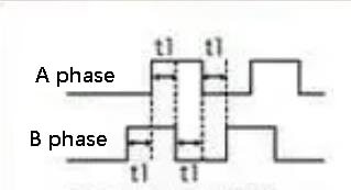
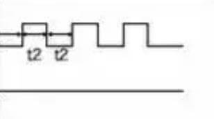
Method 1: Differential Control
Implementation:
The driver receives two high-speed pulses, labeled as 𝑎a and 𝑏b.
The rotation direction of the motor is determined by the phase difference between these two pulses.
If pulse 𝑏b leads pulse 𝑎a by 90 degrees, the motor rotates in the positive direction.
If pulse 𝑏b lags pulse 𝑎a by 90 degrees, the motor rotates in the reverse direction.
Characteristics:
Alternating Pulses: The two-phase pulses alternate, leading to the term “differential control.”
Anti-Interference: This method exhibits higher anti-interference capabilities, making it suitable for environments with strong electromagnetic interference.
Limitations:
Resource Intensive: Requires two high-speed pulse ports for a single motor shaft, which can be a limitation in systems with limited high-speed pulse port availability.
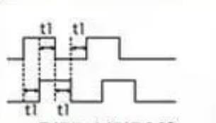
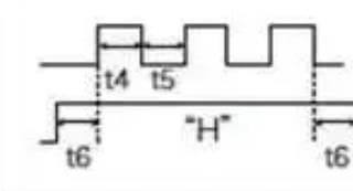
Method 2: Sequential Pulse Control
Implementation:
The driver still receives two high-speed pulses, but they do not exist simultaneously.
When one pulse is active, the other must be inactive.
One pulse controls the positive direction, while the other controls the negative direction.
Characteristics:
Sequential Pulses: Ensures that only one pulse is output at any given time, preventing simultaneous pulse conflicts.
Limitations:
Resource Intensive: Similar to differential control, this method also requires two high-speed pulse ports for a single motor shaft.
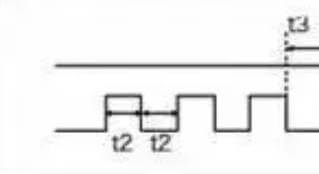
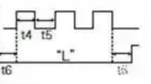
Method 3: Single Pulse with Directional IO Signal
Implementation:
The driver receives a single high-speed pulse signal.
The direction of the motor’s rotation is controlled by an additional directional IO signal.
Characteristics:
Simpler Control: This method simplifies the control logic by reducing the number of pulse signals required.
Resource Efficient: Occupies fewer high-speed pulse ports, making it ideal for smaller systems with limited resources.
Limitations:
Lower Anti-Interference: While simpler, this method may not offer the same level of anti-interference capability as differential control.
Summary
Each pulse control method offers distinct advantages and is suitable for different application scenarios:
Differential Control: Best for high-interference environments due to its superior anti-interference capabilities but requires more resources.
Sequential Pulse Control: Offers a balance between control complexity and resource usage but still requires two high-speed pulse ports.
Single Pulse with Directional IO Signal: Ideal for small systems with limited resources, offering simplicity and efficiency at the cost of potentially lower anti-interference capabilities.
When selecting a control method, consider the specific requirements of your application, including the level of interference, resource availability, and control complexity.
2. Servo Motor Analog Control Mode
In applications where precise speed control of a servo motor is required, analog control can be an effective method. This mode utilizes an analog signal to regulate the motor’s speed, offering a straightforward and flexible approach.
Analog Quantity Selection
The analog control signal can be either a voltage or a current. Each method has its own advantages and considerations:
Voltage Mode
In voltage mode, the control signal is a specific voltage applied to the servo motor’s control input. This method is relatively simple to implement and can even be achieved using a potentiometer for manual adjustments. Here are the key points:
Implementation: Apply a specific voltage to the control signal end.
Ease of Use: Simple setup, often using a potentiometer.
Suitability: Ideal for straightforward applications with minimal environmental interference.
However, voltage signals are susceptible to noise and interference, especially in complex environments. This can lead to unstable motor control, making it less reliable in such scenarios.
Current Mode
Current mode control requires a corresponding current output module to generate the control signal. Despite the additional hardware requirement, current signals offer significant advantages in terms of stability and reliability:
Implementation: Requires a current output module.
Anti-Interference: Strong resistance to environmental noise and interference.
Suitability: Optimal for complex environments where stable control is critical.
The robust nature of current signals makes them preferable in industrial settings or other applications where environmental conditions may affect signal integrity.
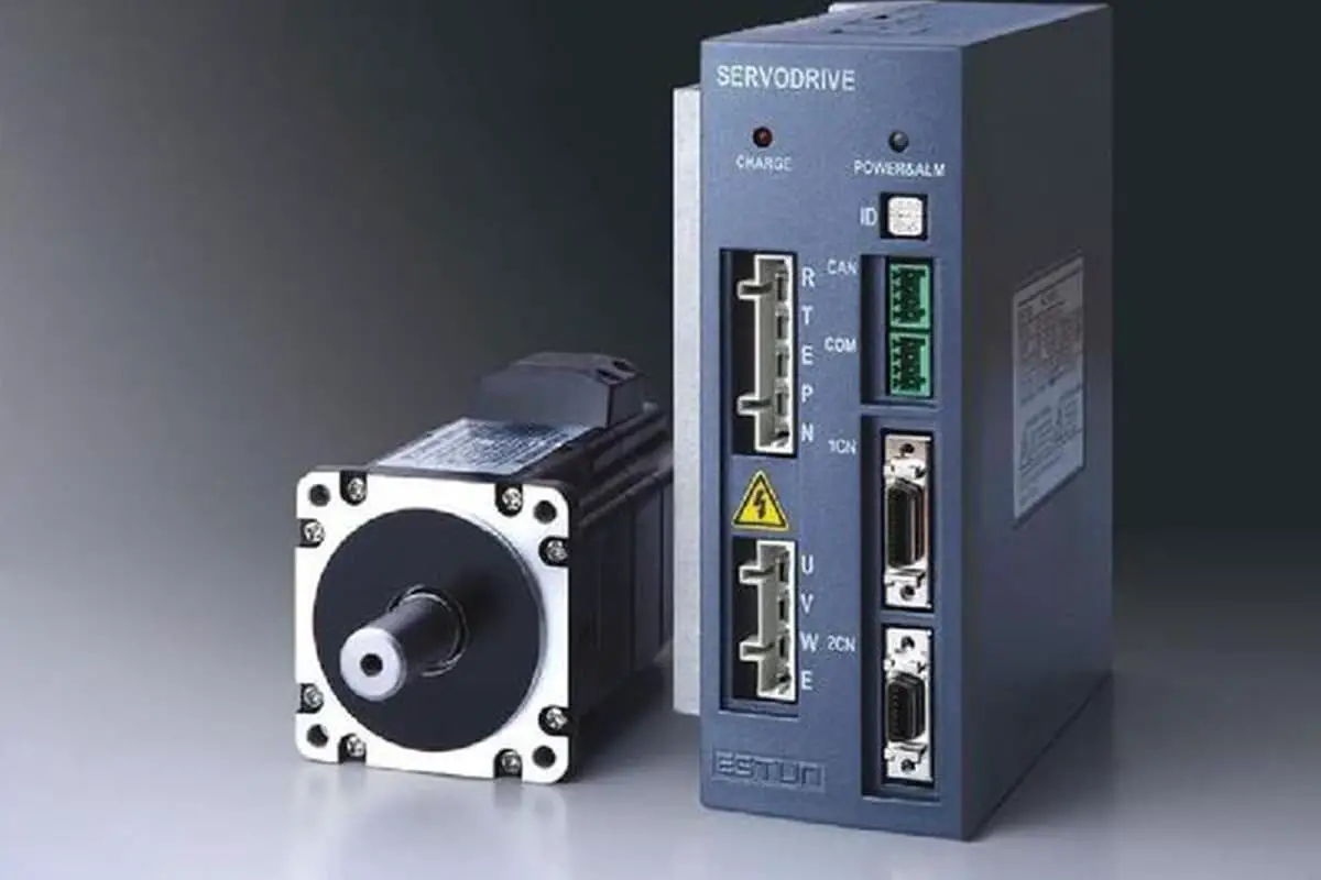
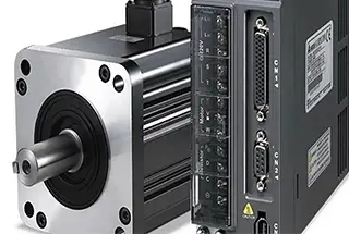
3. Servo Motor Communication Control Mode
Servo motors are critical components in various industrial applications, providing precise control over motion. The communication control mode for servo motors is essential for achieving efficient and accurate operation, especially in complex and large-scale systems. Here, we explore the common communication protocols used for servo motor control and their benefits.
Common Communication Protocols
CAN (Controller Area Network)
Overview: CAN is a robust vehicle bus standard designed to allow microcontrollers and devices to communicate with each other without a host computer.
Advantages: High reliability, real-time capabilities, and error detection mechanisms.
Applications: Widely used in automotive and industrial automation systems.
EtherCAT (Ethernet for Control Automation Technology)
Overview: EtherCAT is an Ethernet-based fieldbus system designed for real-time control applications.
Advantages: High-speed communication, low latency, and synchronization capabilities.
Applications: Ideal for high-performance applications such as robotics, CNC machines, and motion control systems.
MODBUS
Overview: MODBUS is a serial communication protocol originally published by Modicon for use with its programmable logic controllers (PLCs).
Advantages: Simplicity, ease of implementation, and wide adoption.
Applications: Commonly used in industrial environments for connecting electronic devices.
PROFIBUS (Process Field Bus)
Overview: PROFIBUS is a standard for fieldbus communication in automation technology.
Advantages: High data transmission speed, reliability, and extensive diagnostic capabilities.
Applications: Used in factory automation and process automation.
Benefits of Communication Control in Servo Motors
Using communication protocols to control servo motors offers several advantages, particularly in complex and large-scale system applications:
Scalability: The system’s size and the number of motor shafts can be easily adjusted without significant changes to the infrastructure.
Reduced Wiring Complexity: Communication control reduces the need for extensive control wiring, simplifying installation and maintenance.
Flexibility: The built system is highly flexible, allowing for easy integration and reconfiguration of components.
Enhanced Diagnostics: Communication protocols often include diagnostic features that help in monitoring and troubleshooting the system.
Real-Time Control: Protocols like EtherCAT provide real-time control capabilities, essential for applications requiring precise timing and synchronization.
4. Expansion on Servo Motor Control Modes
1. Servo Motor Torque Control
Torque control mode allows for the precise setting of the motor shaft’s external output torque through the input of an external analog signal or direct address assignment. This mode is particularly useful in applications where maintaining consistent material stress is crucial.Example:
If a 10V input corresponds to 5 Nm of torque, then a 5V input will result in 2.5 Nm of torque output.
When the motor shaft load is less than 2.5 Nm, the motor rotates forward.
When the external load equals 2.5 Nm, the motor remains stationary.
When the load exceeds 2.5 Nm, the motor reverses direction (common in gravity-loaded systems).
Applications:
Winding and unwinding devices, such as those used in textile manufacturing or optical fiber pulling equipment, where material stress must remain constant.
Real-time adjustments to the torque setting can be made by altering the analog input or changing the value through communication protocols, ensuring consistent material stress despite changes in winding radius.
2. Servo Motor Position Control
In position control mode, the motor’s rotation speed is typically determined by the frequency of external input pulses, while the rotation angle is controlled by the number of pulses.Features:
Some servo systems allow direct assignment of speed and displacement values through communication.
This mode offers precise control over speed and position, making it ideal for applications requiring high accuracy.
Applications:
Positioning devices
CNC machine tools
Printing machinery
3. Servo Motor Speed Mode
Speed mode allows for control of the motor’s rotation speed via analog input or pulse frequency.Features:
With outer loop PID control from an upper control device, speed mode can also be used for positioning.
The position signal from the motor or the direct load must be fed back to the upper computer for processing.
Supports direct load outer ring position detection, where the motor shaft encoder only measures speed, and a separate device at the load end provides the position signal.
Advantages:
Reduces errors in intermediate transmission
Enhances overall system positioning accuracy
4. Understanding the Three Loops
Servo systems typically operate using three closed-loop negative feedback PID regulation systems: the current loop, the speed loop, and the position loop.Current Loop:
The innermost loop, handled entirely within the servo driver.
Detects and adjusts the output current of each motor phase using a hall device.
Controls motor torque with minimal computational load and fast dynamic response.
Speed Loop:
The second loop, utilizing feedback from the motor encoder.
The PID output of the speed loop sets the current loop, meaning speed control inherently includes current control.
Essential for any control mode, as the current loop forms the control foundation.
Position Loop:
The outermost loop, which can be configured between the driver and motor encoder or between an external controller and the motor encoder/final load.
The position control loop’s internal output sets the speed loop, necessitating the operation of all three loops in position control mode.
This mode involves the most computational effort and has the slowest dynamic response.
Conclusion
Understanding the different control modes and the three-loop system of servo motors is essential for optimizing their performance in various industrial applications. Each mode offers unique advantages and is suited to specific tasks, ensuring precise control over torque, position, and speed.
As the founder of MachineMFG, I have dedicated over a decade of my career to the metalworking industry. My extensive experience has allowed me to become an expert in the fields of sheet metal fabrication, machining, mechanical engineering, and machine tools for metals. I am constantly thinking, reading, and writing about these subjects, constantly striving to stay at the forefront of my field. Let my knowledge and expertise be an asset to your business.
Servo systems are an integral part of electromechanical products, providing the highest level of dynamic response and torque density. Hence, the trend in drive system development is to replace traditional…
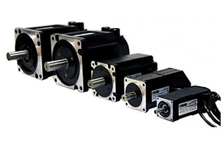
Choosing the right servo motor for your project can be a daunting task with so many options available. This article simplifies the process by breaking down the key considerations: application…
With the improvement in cost-performance ratio of imaging equipment and the speed of computer information processing, alongside the perfection of related theories, vision servo technology has met the technical conditions…
How do modern machines achieve precise control in complex tasks? Servo systems hold the answer. This article delves into the principles behind servo systems, exploring how they function and the…
Ever wondered how machines select the perfect motor? This article unveils the fascinating process behind choosing the right servo motor for various mechanical tasks. Dive in to understand the calculations…
Ever wondered how to set up a servo driver for peak performance? This guide covers everything you need to know about adjusting gain parameters, from position control to speed regulation.…
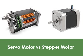
What makes servo motors and stepper motors distinct yet pivotal in modern machinery? This article explores their fundamental differences, advantages, and specific applications. By reading, you'll gain insights into their…
Have you ever wondered why your servo motor suddenly jitters, disrupting your machine's smooth operation? This article uncovers the common causes behind servo motor jitter and provides practical solutions to…
In the fast-paced world of industrial automation, servo motors are the unsung heroes driving precision and efficiency. But with countless manufacturers vying for attention, how do you know which ones…