3 Servo Motor Control Modes Explained
Ever wondered how machines achieve precise movements? This blog dives into the fascinating world of servo motor control modes. From pulse to analog control, we'll explore how each method works…
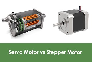
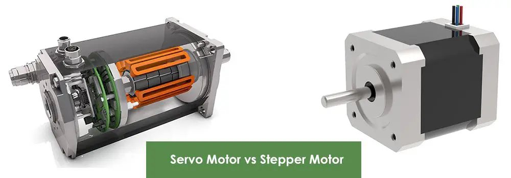
What makes servo motors and stepper motors distinct yet pivotal in modern machinery? This article explores their fundamental differences, advantages, and specific applications. By reading, you’ll gain insights into their control mechanisms, performance characteristics, and ideal usage scenarios, helping you make informed decisions for your engineering projects. Dive in to understand how each motor type can enhance precision and efficiency in various applications.
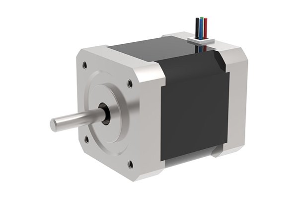
A stepper motor, a type of motor specifically designed for control, converts electric pulses into angular displacement.
When the stepper driver receives a pulse signal, it causes the stepper motor to rotate at a predetermined fixed angle, known as the “step angle,” in the specified direction.
The motor rotates step-by-step at the fixed step angle.
Accurate positioning can be achieved by controlling the number of pulses, and regulating the speed and acceleration of motor rotation can be accomplished by controlling the pulse frequency.
Reversing the motor’s rotation direction can be achieved by changing the sequence in which the windings are energized.

A stepper motor requires a specialized stepper motor driver to operate. This driver consists of an impulse control unit, a power drive unit, and a protection unit.
The power drive unit amplifies the pulses generated by the impulse control unit and is directly connected to the stepper motor, serving as the power interface between the stepper motor and the microcontroller.
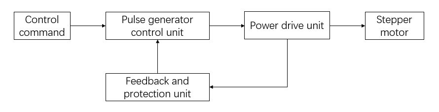
The control instruction unit receives pulse and direction signals and generates a set of corresponding pulses, which are then transmitted to the stepper motor through the power drive unit.
The stepper motor then rotates a set step angle in the indicated direction.
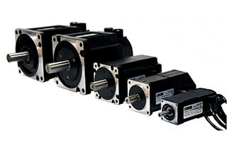
The stepper motor has several key technical specifications, such as maximum static torque, starting frequency, and operating frequency.
Generally, the smaller the step angle, the greater the maximum static torque, and the higher the starting and operating frequencies.
Therefore, the operation mode places a strong emphasis on subdivision drive technology.
This method improves the stepper motor’s torque and resolution and completely eliminates low-frequency oscillation.
As a result, subdivision drive performance is superior to other types of drives.
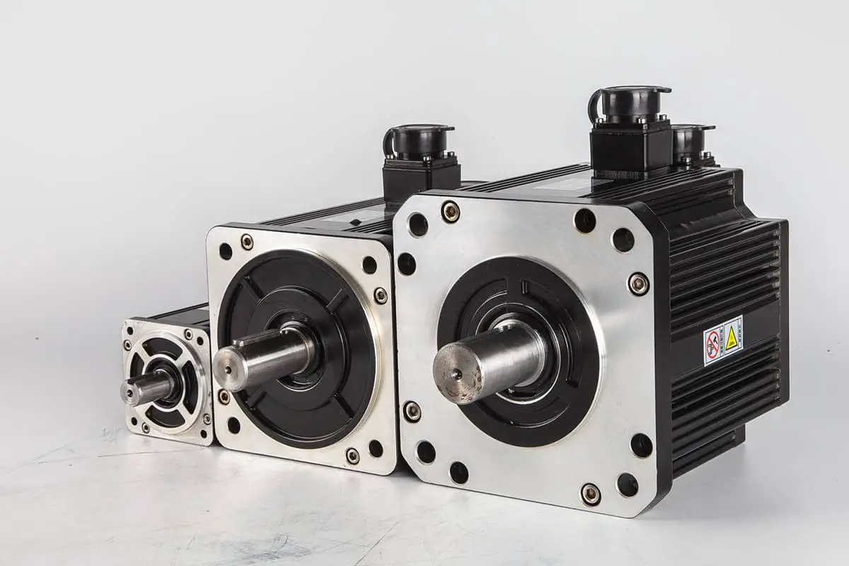
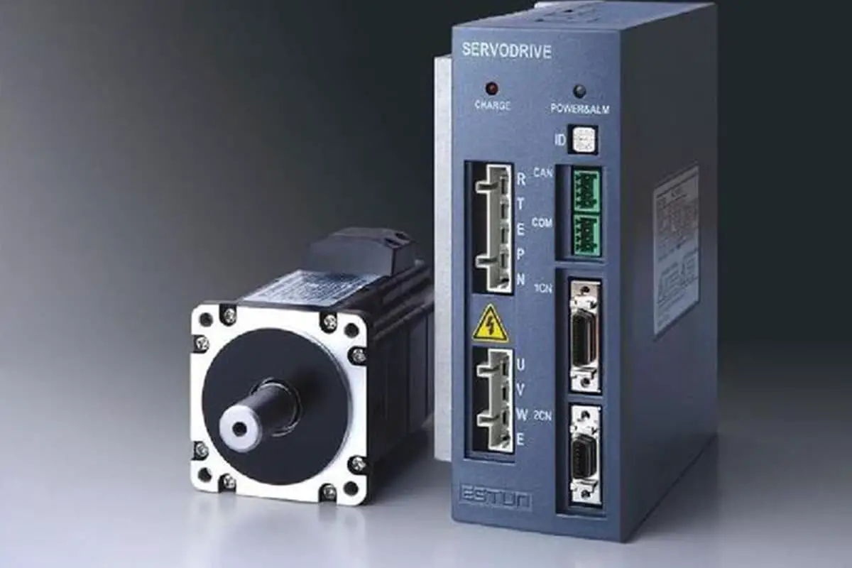
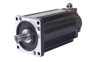
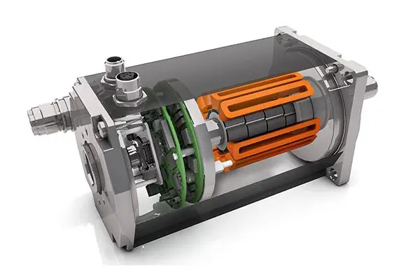
The rotor inside a servo motor is a permanent magnet. The driver controls U/V/W three-phase electricity to create an electromagnetic field, causing the rotor to rotate under the influence of this magnetic field. The motor’s own encoder provides feedback signals to the driver, which adjusts the rotor’s rotation angle based on the feedback value and target value.
The servo motor, also referred to as an executive motor, is used as an actuator in automatic control systems to convert received electrical signals into angular displacement or angular velocity on the motor shaft.
Servo motors come in two varieties: DC and AC.
When a servo motor receives a pulse, it rotates the corresponding angle to produce displacement. This is because the servo motor itself emits pulses, with each rotation angle emitting a corresponding number of pulses that form a closed loop with the pulses received by the servo motor.
This allows the system to monitor the number of pulses it sends to the servo motor and the number of pulses it receives, enabling precise control and accurate positioning.
In terms of performance, AC servo motors are superior to DC servo motors. AC servo motors use sine wave control, resulting in low torque ripple and high capacity.
DC servo motors, on the other hand, use trapezoidal wave control and have relatively poor performance.
However, brushless servo motors in DC servo motors perform better than brush servo motors.
The interior of a servo motor contains a permanent magnet rotor.
The actuator controls U/V/W three-phase electricity to generate an electromagnetic field, causing the rotor to rotate.
Additionally, the motor’s encoder provides feedback signals to the driver.
The driver adjusts the rotor’s rotation angle based on the feedback value and the desired target value.
Brush DC servo motor drive:
The operating principle of the motor is similar to that of a standard DC motor.
The actuator has a three-loop structure, consisting of a current loop, speed loop, and position loop, arranged in order from the inside out.
The current loop’s output controls the motor’s armature voltage.
The current loop’s input is the speed loop’s PID output, the speed loop’s input is the position loop’s PID output, and the position loop’s input is the specified input.
The control diagram is illustrated above.
Brushless DC servo motor drive:
The power source is DC, which is transformed into U/V/W AC power by an internal three-phase inverter.
The driver also employs a three-loop control structure (current loop, speed loop, position loop), and its driving control principle is the same as previously described.
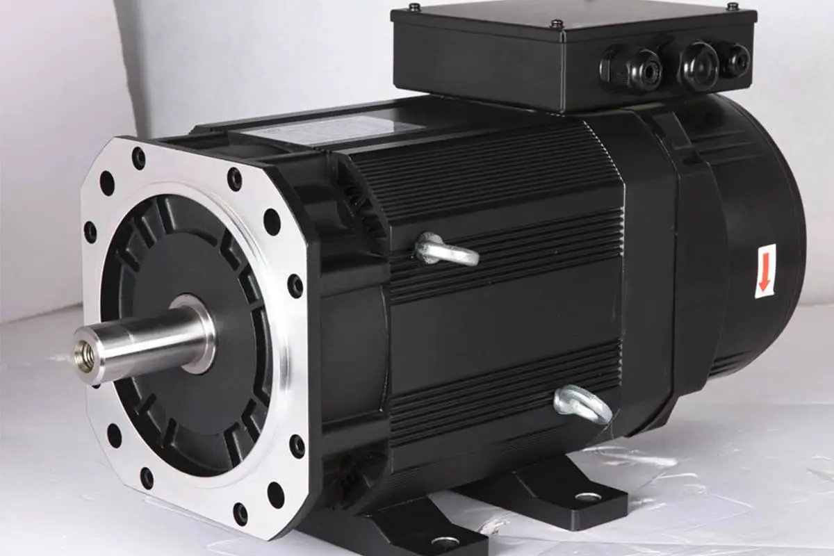
AC servo motor drive:
The system can be divided into two separate modules: the power panel and the control panel, each with distinct functions.
The control panel outputs PWM signals through a corresponding algorithm, serving as the drive circuit for the drive signal, to modify the output power of the inverter and achieve control of the three-phase permanent magnet synchronous AC servo motor.
The power drive unit first converts the input three-phase electricity or municipal electricity into direct current electricity through a three-phase full-bridge rectifier circuit.
The three-phase permanent magnet synchronous AC servo motor is then driven by the commutator of a three-phase sinusoidal PWM voltage-type inverter, following the rectification of three-phase or municipal electricity.
This process is simply an AC-DC-AC conversion.
The control unit is the core of the entire AC servo system and performs system position control, speed control, torque control, and current control.
Control Accuracy
The more phases and beats a stepping motor has, the greater its accuracy.
The servo motor obtains feedback from its own encoder, and the more scales the encoder has, the higher its precision.
Low-Frequency Characteristic
Stepper motors are prone to low-frequency vibration at low speeds.
To combat this, low-speed operation often employs damping or subdivision technology.
In contrast, servo motors run smoothly without vibration, even at low speeds.
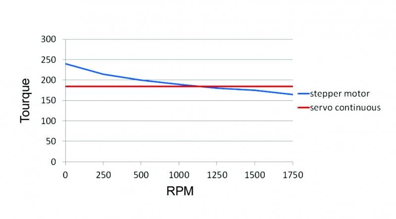
Torque-frequency Characteristic
The output torque of a stepper motor decreases with an increase in speed and drops significantly at high speeds.
In contrast, a servo motor provides constant torque output at its rated speed and constant power output at its rated speed.
Overload Capacity
A stepper motor lacks overload capacity, while a servo motor possesses strong overload capacity.
Operation Performance
Stepper motors operate under open-loop control, making them susceptible to losing step or ceasing rotation if the starting frequency is too high or the load is too heavy. If the speed is too high, it can also result in overshooting.
On the other hand, the AC servo drive system uses closed-loop control. The servo motor’s driver samples the motor encoder’s feedback signal directly, forming internal position and speed control loops. As a result, stepper motors are less likely to lose step or overshoot, making the control performance more reliable.
Speed Response Performance
Stepper motors take hundreds of milliseconds to accelerate from a static state to operating speed.
In comparison, AC servo systems have excellent acceleration performance, typically taking only a few milliseconds, making them suitable for applications that require quick starts and stops.

As the founder of MachineMFG, I have dedicated over a decade of my career to the metalworking industry. My extensive experience has allowed me to become an expert in the fields of sheet metal fabrication, machining, mechanical engineering, and machine tools for metals. I am constantly thinking, reading, and writing about these subjects, constantly striving to stay at the forefront of my field. Let my knowledge and expertise be an asset to your business.