X-ray Residual Stress Measurement: Principles and Applications
Imagine knowing exactly how much stress your metal components can handle without cutting them open. X-ray residual stress measurement offers this insight by using non-destructive testing methods. This article explores how X-ray diffraction techniques accurately measure internal stresses, enhancing product reliability and longevity. Learn how different methods like the sin²ψ and cosα techniques provide precise stress data, ensuring your metalwork meets the highest standards. Dive into these advanced measurement techniques to understand their principles, applications, and benefits for industrial engineering.
Residual stress is a type of internal stress referred to as such in engineering. The distribution of residual stress in a workpiece is often uneven, which can significantly impact its static strength, fatigue strength, shape stability, and corrosion resistance. As a result, measuring residual stress is crucial.
There are two main methods for measuring residual stress: destructive testing and non-destructive testing. The destructive testing method involves removing a portion of the workpiece and calculating the residual stress based on the corresponding strain and displacement. Common destructive testing methods include the drilling method and ring core method.
The non-destructive testing method involves establishing a relationship between residual stress and a physical quantity that can cause a change in the material (such as crystal plane spacing, ultrasonic wave propagation rate, or magnetic permeability) to calculate the residual stress. Non-destructive testing methods include X-ray diffraction, neutron diffraction, magnetic, and ultrasonic methods.
X-ray diffraction is the most widely used method for residual stress measurement, due to its mature principles and well-established methods, as well as the availability of increasingly sophisticated testing equipment, including laboratory instruments, portable instruments for field measurement, and specialized devices for special circumstances.
The X-ray diffraction method for measuring residual stress was first proposed by Russian scholar Akchenov in 1929 and equated macroscopic strain with lattice strain. In 1961, German scholar Macherauch further developed the sin2ψ method based on Akchenov’s idea, making the measurement of residual stress by X-ray diffraction a reliable and widely used technology.
Over the past 60 years, X-ray diffraction has developed into several different measurement methods, with sin2ψ method and cosα method being the two main methods currently used.
1. Classification of X-ray diffraction residual stress measurement methods
To master the X-ray diffraction technology for measuring residual stress, it is important to understand its various methods.
(1) The X-ray diffraction residual stress measurement methods can be categorized into two main approaches: the sin2ψ method and the cosα method.
(2) The sin2ψ method can further be classified based on the calculation method of residual stress, into the 2θ method, the d-value method, and the strain method.
(3) Based on the geometric relationship between ψ and 2θ, the sin2ψ method can be divided into two types: the co-tilt method and the roll method.
(4) The measurement method can also be differentiated based on the scanning mode of the X-ray tube and counter tube, into the fixed ψ0 method and the fixed ψ method.
(5) Within the roll method, there are three sub-categories: the standard roll method, the modified roll method, and the roll fixation method ψ.
(6) The positive and negative ψ measurement method is used to determine shear stress τφ.
(7) X-ray diffraction is typically used to measure the stress in a specific direction at a particular point, but there are also methods for measuring the principal stress at a point.
(8) The swing method can be divided into several sub-categories: the ψ0 swing method, the ψ swing method, the Debye ring swing method, the φ angle swing method, and the X/Y reciprocating translation method.
(9) In terms of diffraction geometry, there are three approaches: the focusing method, the quasi-focusing method, and the parallel beam method.
2. sin2ψ method for determination of residual stress by X-ray diffraction
The stress is determined by the strain. In the case of polycrystalline materials, the residual stress is estimated by the statistical result of lattice strain in the relevant region.
Thus, residual stress can be determined by measuring lattice strain through the X-ray diffraction technique.
The residual stress of the material reflects the macro strain.
The macro strain is equivalent to the lattice strain.
Lattice strain represents the relative change in crystal plane spacing, which can be calculated using a diffraction device based on the Bragg law.
This summarizes the X-ray diffraction method for measuring residual stress.
2.1 Bragg’s law
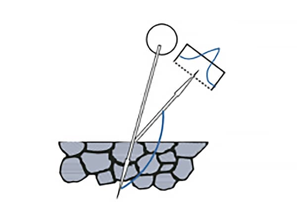
When a polycrystal is exposed to an X-ray beam with a specific wavelength (λ), the maximum intensity of the reflected X-ray (i.e., the diffraction peak) will be observed at a specific diffraction angle (2θ), as illustrated in Figure 1. This phenomenon is known as X-ray diffraction.
The relationship between the X-ray wavelength (λ), the crystal plane spacing (d) and the Bragg angle (θ) is described by the following equation (1).
In the X-ray diffraction analysis of residual stress, the appropriate target material for the X-ray tube is selected to determine the suitable wavelength (λ). The diffraction angle (2θ) is then measured using a diffraction device. Based on the measurement, the crystal plane spacing (d) of the relevant crystal plane can be calculated.
Fig. 1 X-ray diffraction geometry
2.2 Azimuth angle of crystal plane diffraction ψ
As per the reflection law of optics, the normal of the crystal plane involved in diffraction must lie on the bisector between the incoming and reflected rays, as illustrated in Figure 2.
The angle between the normal of the diffraction crystal plane and the normal of the sample surface is known as the azimuth angle of the normal of the diffraction crystal plane, which is usually represented by ψ.
Bragg’s law allows for the determination of the spacing (dψ) of crystal planes in a specified orientation (ψ).
If the spacing (d0) of crystal planes in the stress-free state is known, the lattice strain (εψ) in the designated orientation can be calculated.
2.3 Scope of application of sin2ψ method
S1, S2, and S3 are the axes of the specimen surface and S1 is defined by the researcher.
Figure 3 illustrates the coordinate system used for measuring residual stress through X-ray diffraction.
Fig. 3 Coordinate system for X-ray diffraction stress measurement
According to the generalized Hooke’s law, the strains of these crystal planes are influenced by the stress tensor at point O and are closely linked to the sine and cosine of φ and ψ, the Young’s modulus of the material, and Poisson’s ratio.
Hence, it is possible to determine the three-dimensional stress at point O, including stress (σφ).
The expression for strain in the OP direction can be derived from the theory of elasticity.
For most materials and components, the penetration depth of X-rays is only a few microns to tens of microns, thus it is commonly assumed that σ33=0.
Therefore, the strain in the OP direction is represented by equation (2).
The sin2ψ-method formula is derived based on bragg’s law and elastic theory.
The objects considered in the theory of elasticity are assumed to be homogeneous, continuous, and isotropic media.
However, this assumption is only valid for polycrystalline metal materials if the grain size is fine and there is no texture present.
Fig. 4 shows the functional relationship curve of εn and sin2ψ for isotropic materials, materials with stress gradient or composition gradient, materials with shear stress, and anisotropic materials with texture.
As shown in Fig. 4c), if the shear stress τ13≠ 0, τ23≠0 and sin2ψ curve have ± ψ bifurcation, σφ and τφ can be obtained by using the measured strain data ε﹢ψ and ε﹣ψ on a series of ± ψ angles, as shown in Formula (4) and Formula (5).
It’s important to note that the sin2ψ curve shown in Figure 4c) is unlikely to have a ±ψ bifurcation.
This is because the X-ray used for diffraction has limited penetration depth into the tested material, usually only a few microns to tens of microns.
Consequently, the stress components perpendicular to the material surface can be considered as zero.
Only when the principal stress plane deviates from the surface of the specimen under the condition of special machining (such as powerful and large cutting amount grinding) can τ13≠0 and τ23≠0 occur.
The ±ψ bifurcation is not a common occurrence, and the fitting curve often lacks the ellipse attribute. This is largely due to the systematic error in the ±ψ mechanism of the goniometer. Therefore, there is no need to overly stress the importance of ellipse fitting.
In conclusion, the practical and implementable process of determining residual stress through X-ray diffraction involves selecting a few ψ angles (or several pairs of ±ψ angles) and measuring the corresponding diffraction angle (2θφψ), followed by calculation.
Scholars have developed various methods for arranging the spatial geometric relationship between the ψ plane and 2θ plane, determining the diffraction curve, and performing calculations.
3. True strain method, 2θ Method and d-value method
The diffraction angle 2θφψ is measured by the X-ray diffraction device, and the corresponding crystal plane spacing is calculated as dφψ according to the Bragg law, then the lattice strain εφψ can be expressed by the crystal plane spacing, as shown in Formula (6).
The true strain is directly substituted into Equation (3), Equation (4) and Equation (5) to calculate the stress, which is the true strain method expression.
The true strain method is adopted, and the exact values of d0 and θ0 are not required.
In most cases, the true strain method has significant advantages.
Approximate equations can also be used to calculate the strain, as shown in Eq. (7) and Eq. (8).
The calculation formula of 2θ method is shown in equation (9).
Where, K is the stress constant, and its calculation formula is shown in equation (10).
Where: ν is the Poisson’s ratio of the material.
For some materials, θ0 varies greatly with the chemical composition, and the results will have large deviation if the stress constant is used.
The true strain method has been included in the European Union standard EN 15305-2008 Non destructive testing — Test method for residual stress analysis by X-ray diffraction and GB/T 7704-2017 Non destructive Testing X-ray Stress Measurement Method.
XL-640 domestic stress meter lists the true strain method as the default stress calculation method, and 2θ method can be selected for calculation.
4. Co tilt method and roll method
The coplanar method is a measurement method in which the 2θ plane coincides with the ψplane (stress direction plane), as shown in Fig. 5.
Fig. 5 Geometric Diagram of the Same Tilt Method
With the same inclination method, the X-ray incidence angle ψ0 is dominant, while the angle ψ can be calculated, as shown in Eq. (11) and Eq. (12).
In the stress test of the actual workpiece, when the test point is located in a similar shallow groove, the testing space of the goniometer is limited, so the same inclination method is more suitable.
The roll method is a measurement method in which the 2θ plane and the ψ plane (stress direction plane) are perpendicular to each other, as shown in Fig. 6.
Fig. 6 Geometric Diagram of Roll Method
The key feature of the Roll method (χ method) is its small absorption factor of the diffraction peak, which contributes to enhanced measurement accuracy.
The 2θ and ψ ranges can be fully extended as necessary. For certain materials, diffractive rays with low peak positions (such as peaks below 145°) can be utilized for stress measurement.
However, the 2θ plane and the ψ plane of this method are perpendicular to each other, requiring a three-dimensional space, making it challenging to apply to the measurement of narrow spaces.
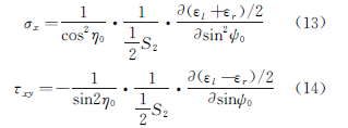
A foreign company’s stress instrument product employs a modified Roll method with double detectors, as shown in Figure 7. Its geometric layout is depicted in the figure.
Fig. 7 Geometric Diagram of Modified Roll Method
As early as January 1977, Li Jiabao, Institute of Metals, Chinese Academy of Sciences, proposed this test method and calculation formula, as shown in Eq. (13) and Eq. (14).
The roll method can be divided into two categories: the fixed ψ0 method and the fixed ψ method.
The fixed ψ method is considered superior to the fixed ψ0 method due to its more accurate principles and effective results in practice.
By combining these two methods, the roll fixed ψ method, the absorption factor can be equal to 1.
This means that the diffraction peak will not tilt at the back bottom, the peak shape will remain symmetrical, and the peak shape and intensity will remain unchanged, even if the angle ψ changes, as long as there is no texture.
This feature greatly enhances measurement accuracy, making the roll fixed ψ method an ideal measurement technique.
5. Swing method
The swing method involves using each set angle ψ (or ψ0 angle) as a center point, and having the X-ray tube and detector swing to the left and right at a specific angle (±Δψ or ±Δψ0).
This method increases the number of grains that participate in diffraction, making it an effective method for measuring the stress in coarse-grained materials.
Other swing methods, such as the φ angle swing method and X/Y translation swing method, can also be used, and different swing methods can even be combined for testing purposes.
6. Determination of residual stress by X-ray diffraction cosα method
In 2012, PULSTEC, a company based in Japan, introduced a stress instrument that utilizes two-dimensional detector technology for the first time.
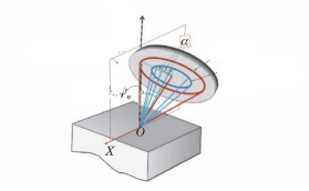
This instrument operates using a single incident mode and a two-dimensional detector to gather X-ray diffraction information, allowing it to quickly collect Debye ring data at the test point.
Since the angle ψ formed by the crystal face normal and the sample surface normal does not lie in the same plane for each point on the Debye ring, the sin2ψ method cannot be used to calculate stress. Instead, the angle α, or cosα method, is employed (as shown in Figure 8).
Fig. 8 Geometric Diagram of Method cosα
This testing method is ideal for measuring surface stress in large steel structures.
However, it has limitations when testing coarse-grained materials or materials with texture.
The cosα method is based on the principles of elasticity, as demonstrated by Equations (15) and (16).
Figure 9 shows the maximum range of angle ψ that can be acquired using a “full two-position detector” (with an incidence angle of 45°).
Angle α lies on the Debye ring plane, which is the center angle of each point on the Debye ring.
Fig. 9 Location of data points of method sin2ψ in s curve
Both methods for measuring residual stress through X-ray diffraction are based on the same mechanical principle.
The strain tensor can be transformed in the space angle, and the α angle used in the cosα method can be fully converted to the ψ angle.
In essence, the cosα method is essentially an approximation of the sin2ψ method.
7. Comparison of the residual stress of hot-rolled steel plate measured by different instruments
Typically, hot-rolled steel plates are considered to be free of texture. However, some parts of the steel plate may exhibit texture due to various factors.
Despite this, many users still opt to use X-ray diffraction to measure residual stress in such cases.
For example, if a hot-rolled steel plate with texture is selected, the test conditions and results can be seen in Table 1 and Table 2. The test report for the residual stress measurement at point Z (0) by each instrument is shown in Figures 10-13.
Table 1 Test Parameters for Measuring Residual Stress of Hot Rolled Steel Plate with Different Stress Instruments
Equipment Type
μ-X360S
PROTO LXRD
X-RAYBOT
XL-640
test method
cosα
sin2ψ
sin2ψ
sin2ψ
Voltage/kV
20
30
20
25
Current/mA
1
25
1
6
Illuminated spot/mm
1
1
1
1
ψ Range/(°)
–
-35~35
-40~40
0~45
Strain calculation method
–
D value method
Strain method
Strain method
Peak determination method
–
PersonVII
Middle point
Cross correlation method
Residual stress/MPa
78
213.6
144
113
Table 2 Residual Stress of Hot Rolled Steel Plate Measured by Different Stress Instruments
Test point
μ-X360S
PROTO LXRD
X-RAYBOT
XL-640
Z(5)
29,47
122
107
77
Z(4)
37,52
135
112
70
Z(3)
74,70
104
95
67
Z(2)
38,28
153
99
134
Z(1)
37,64
166
122
101
Z(0)
64,78
144
213
113
Z(-1)
72,71
138
97
139
Z(-2)
62,52
134
83
145
Z(-3)
75,70
120
93
153
Z(-4)
63,56
114
80
148
Z(-5)
79,27
94
93
152
Fig. 10 Debye ring at point Z (0) measured with μ-X360S-type stress meter
Fig. 11 2θ-sin2ψ curve of Z (0) measured by PROTO LXRD stress meter
Fig. 12 2θ-sin2ψ Curve of Measuring Point Z (0) with X-RAYBOT Stress Meter
Fig. 13 ε-sin2ψ-curve of Z (0) measured with XL-640 stress meter
The residual stress measured by c method is smaller than that measured by s method.
For the Z (0) test point, the stress meter is used. According to the principle of equal spacing of sin2ψ, 8 ψ angles are selected within the range of 0 °~45 °.
The results are shown in Fig. 14-15. It can be seen that the sin2ψ curve of the material presents a “shock” type due to the texture.
The ordinate of the sin2ψ curve in Fig. 13 is strain ε. After changing the ordinate to 2θ, perform linear fitting. The results are shown in Fig. 14.
The slope M of the fitting line is -0.355, and the residual stress σis 113MPa.
Fig. 14 Fitting results of 2θ-sin2ψ curve measured by XL-640 stress meter at point Z (0)
The ψ range selected by the μ-X360S stress meter is equivalent to the first two 2θ values of shielding, and then the straight line fitting is performed. The results are shown in Fig. 15.
Fig. 15 Fitting Results of 2θ-sin2ψ Curve of Z (0) Measured by μ-X360S-type Stress Instrument
Use PROTO LXRD stress meter to test the selected ψ range, shield the last three 2θ values in Fig. 14, and then perform linear fitting. The results are shown in Fig.16.
Fig. 16 Fitting results of 2θ-sin2ψ curve measured by PROTO LXRD stress meter at point Z (0)
It can be seen from Figure 12 that the maximum sin2ψ value of point Z (0) is 0.4 by using the X-RAYBOT stress meter.
According to the selected ψ range, shield the last two 2θ values in Fig. 14, and then perform linear fitting. The results are shown in Fig. 17.
Fig. 17 Fitting Results of 2θ-sin2ψ Curve of Z (0) Measured by X-RAYBOT Stress Tester
Due to the texture of the material, its sin2ψ curve is oscillatory.
The selected ψ angle range is different, resulting in differences in the slope and residual stress values obtained from the fitting line.
For materials with unknown texture and coarse grain, it is not advisable to choose a narrow ψ range and a small number of ψ stations for residual stress measurement, as this can lead to significant measurement errors.
Linear fitting may not be appropriate for materials with textured sin2ψ curves that are oscillatory.
During the measurement process, linear fitting is often used to mitigate fluctuations caused by vibrations and measurement errors.
It may not be feasible to reach a ψ angle of 45°, as this could be influenced by the penetration depth. A larger angle is more likely to produce more accurate results, provided that the penetration depth can be ignored.
For materials with coarse grain or texture, the ψ angle range should be expanded as much as possible to eliminate the effects of nonlinear ε-sin2ψ distribution. This can be achieved by measuring both ±ψ angles.
The accuracy of the fitted straight lines can be improved by using the least squares method for fitting regression, and by increasing both the ψ range and the number of ψ stations. This will result in more reliable test values.
The measurement accuracy can also be improved by increasing the X-ray exposure area or by increasing the number of diffraction grains participating through the swing method.
8. Conclusion
(1) The sin2ψ method can be used to determine residual stress with improved accuracy by increasing the range of ψ and selecting more ψ stations. However, this method has limitations as it involves single exposure, which can result in large measurement errors if the range of ψ is not sufficient.
(2) In the measurement methods that utilize the sin2ψ principle, the roll method is superior to the tilt method. It is recommended to use the roll method whenever the space conditions at the measurement point permit. For measuring residual stress in grooves of certain components, the co-inclination method is commonly used.
(3) The true strain method is a preferred method for calculating residual stress.
(4) The sin2ψ method is considered a standard method for this purpose. To obtain the most accurate results, the angle ψ should be set using the sin2ψ-value bisection method and as many ψ angles as possible should be measured.
As the founder of MachineMFG, I have dedicated over a decade of my career to the metalworking industry. My extensive experience has allowed me to become an expert in the fields of sheet metal fabrication, machining, mechanical engineering, and machine tools for metals. I am constantly thinking, reading, and writing about these subjects, constantly striving to stay at the forefront of my field. Let my knowledge and expertise be an asset to your business.
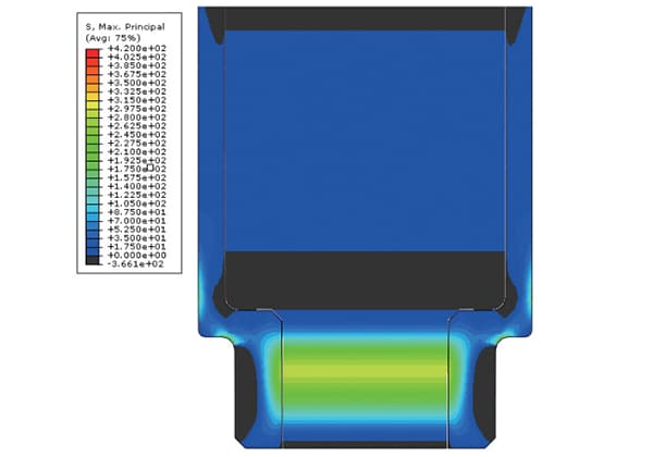
Abstract: The residual stress of butt joint of X80 pipeline steel was simulated by means of finite element analysis, and the distribution of residual stress was obtained. The prediction results…
Have you ever wondered why a perfectly machined component suddenly fails without warning? This mystery often traces back to residual stress. Residual stress, the unseen force within materials, can drastically…
Have you ever wondered why cracks appear in metal parts during manufacturing? In this insightful blog post, we'll dive into the intriguing world of forging cracks, heat treatment cracks, and…
Currently, 3D printing technology is widely used in automotive manufacturing, aerospace and defense, consumer goods, electrical and electronic devices, biomedical applications, cultural and creative jewelry, construction engineering, and education, among…
I. What Is Nondestructive Testing? Nondestructive testing is a general term that refers to all technical means used to detect defects or nonuniformity in an object being tested, by utilizing…
During a test of the cylinder head tightness of a gas engine, water leaked, and after disassembling and inspecting the engine, cracks were found in the spark plug bushing. The…