Abrasive Water Jet Cutting Technology: What You Need to Know
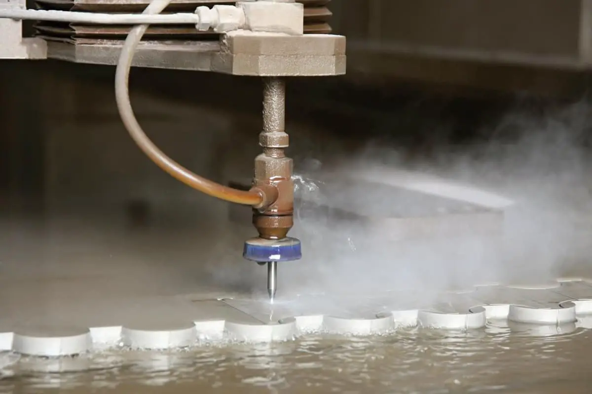
Imagine cutting through steel or marble with nothing more than a jet of water. This is the power of abrasive water jet technology, a groundbreaking method that uses high-pressure water…
How can operators stay safe while using CNC water jet cutting machines? This article highlights crucial safety guidelines, from startup preparations to troubleshooting common issues. You’ll learn essential precautions, such as wearing protective gear, avoiding high-pressure zones, and proper shutdown procedures. Understanding these guidelines ensures not only personal safety but also the longevity and efficiency of the equipment.
Safety Precautions

Check whether the oil tank is short of oil, add oil to the upper limit of the oil level gauge in the oil tank, and tighten the oil tank cap. Loosen the oil pipe at the return port of the plunger pump and pour oil into the plunger pump until it is full, then tighten the return oil pipe.
Turn on the power of the air pump and turn on the air gun switch when the pressure at the outlet of the air pump is ≥0.4 MPa. Air spraying out indicates that the gas supply is normal.
Start the power supply of the water supply pressurization pump, observe the water pressure indicator ≥0.2 MPa, and water flows out at the joint of the cutter head and the connecting rod, indicating that the cutting water supply is normal.
Turn on the electrical main switch on the side of the high-pressure generator, the power switch of the industrial computer, and after the industrial computer enters the WINDOWS startup interface, click the waterjet cutting software to enter the software control interface.
Momentarily press the “Oil Pump Switch” button to check that the motor rotates in the same direction as the arrow on the oil pump body.
Start the oil pump motor and adjust the control pressure of the relief valve to a low value.
Open the double one-way throttle valve at both ends of the electric-hydraulic reversing valve, adjust the magnetic switch to the appropriate position, and the booster is in idle running state. Run for 5-10 minutes, observe that there is no abnormality in oil temperature and pump head temperature, and turn off the oil pump by pressing the “Oil Pump Switch” button to complete the debugging of the hydraulic system.
Install the energy converter (gem), press the “Oil Pump Switch” button to turn on the oil pump, press the “Air Valve Switch” to turn on the high-pressure water switch of the cutting head, and press the “High Pressure Switch” to start the high-pressure generator. The cutting head will spray high-pressure water.
Note: When operating in manual interface mode, first turn on the air valve switch, then turn on the high-pressure switch, otherwise it may cause dangerous pressure buildup in the system. When shutting down, turn off the high-pressure switch first, and then the air valve switch.
Adjust the relief valve knob to gradually increase the pressure in sections. Keep it at 1-2 minutes for every 1MPa increase. During the adjustment, pay attention to check for any oil or high-pressure water leakage, abnormal vibration, and noise. Stop adjusting when the pressure gauge pointer is at 15 MPa and the swing range is ≤3 MPa.
Adjustment of electric-hydraulic reversing valve: Check whether there is any impact sound in the hydraulic cylinder. If so, determine which side it is on and adjust the double one-way throttling valve on that side clockwise until the impact sound disappears.
Repeat turning on and off the high-pressure water switch. If the high-pressure water switch is sensitive, the debugging of the high-pressure generator system is completed.

Hoist the steel plate onto the cutting platform and adjust the bottom and side of the steel plate to be parallel to the X and Y axes of the platform, respectively.
Load cutting sand into the sand bucket and connect the sand pipe.
Copy the DXF graphic file into the computer.
Load the graphic file to be cut in the cutting interface.
Move the cutting head to the origin of the graphic file setting, adjust the distance between the cutting head and the steel plate height, set the current coordinates to “0,0,0” in the “Manual” interface, and set the “Cutting Speed” and “Relay Delay” in the “Parameter Settings” interface.
In the “Auto” interface, press the “Start from Beginning” button to start cutting.
Pay close attention to the distance between the cutting head and the plate during the cutting process. The best cutting height of the cutting head from the workpiece is 3mm-5mm. It is strictly forbidden to run without supervision, which may cause the sand pipe to break, serious damage to the cutting head and the machine’s walking mechanism.
If sand breaks during the cutting process, immediately press the “ESC” key to stop the machine, and handle the sand valve and sand delivery pipe. Re-cut any uncut part. The method is to press “Begin Any Section” in the “Auto” interface, enter the program section number, and press “OK” to start cutting from a previous program section.
Before replacing the workpiece after cutting one workpiece, move the cutting head to the far end to prevent the cutting head from being damaged during loading.
The oil temperature during cutting should be controlled below 65°C. Immediate cooling measures should be taken if the oil temperature exceeds this value.
If one of the following situations occurs, stop the machine immediately for maintenance:
After all the work is completed, exit the system, shut down the computer in the WINDOWS interface, then turn off the electrical main switch on the side of the high-pressure generator, and finally turn off the power supply of the cutting water pressurization pump and the air pump power supply.
| Material | Thickness (mm) | Cutting Speed (mm/min) | Cutting Pressure (MPa) |
| Steel Plate Stainless Steel Plate | 2 5 10 20 40 80 100 | 850~1100 400~550 160~240 60~90 25~40 10~15 3~5 | 300 (The pointer shakes, according to the center value) |
| Note: The lower the cutting speed, the better the quality of the cut. | |||
| Material | Thickness (mm) | Cutting Speed (mm/min) | Cutting Pressure (MPa) |
| Aluminum Plate | 2 5 10 20 40 80 | 1100~1500 650~950 240~360 120~180 50~80 20~30 | 300 (The pointer shakes, according to the center value) |
| Note: The lower the cutting speed, the better the quality of the cut. | |||
The following image shows a cutting cross-section, which guarantees a normal cutting effect of 3 roughness and cannot be lower than this.

Oil Temperature: ≦ 65℃
Secondary Pressurized Pump Outlet Water Pressure: 6~8 kgf/cm2
Jewel Service Life: 50~80 hours
Sand Pipe Service Life: 200 hours
| Serial number | Fault phenomenon | Cause of occurrence | Elimination methods |
| 1 | Oil pump noise | 1) Blocked suction oil filter | Clean or replace the oil filter core with a new one |
| 2) The viscosity of the oil is too high | Use lubricating oil with specified grades according to seasons | ||
| 3) The fuel tank is not breathable | Clean the oil tank air filter element | ||
| 4) Low fuel tank level | Fill to the upper limit of the liquid level gauge | ||
| 2 | There is foam in the oil | 1) Oil suction pipe leaking | Eliminate air leakage or replace with a new pipe |
| 2) Oil pump shaft seal leakage | Replace the sealing ring | ||
| 3 | Excessive heating of the oil pump | 1) Oil pump worn or damaged | Repair or update |
| 2) The viscosity of the oil is too low, too high, or deteriorated | Replace with new oil | ||
| 4 | Overflow valve whistling | Damaged spring or valve core or blocked damping hole | Replace damaged parts or clean them |
| 5 | Oil temperature too high | Excessive overflow rate of the overflow valve | Reduce overflow to match high pressure |
| 6 | Hydraulic system without pressure | 1) There is air in the pump head of the oil pump, and the oil has not come out | Remove the oil return pipe for inspection and fill the pump head with oil |
| 2) The solenoid overflow valve core is stuck or has no signal | Clean the overflow valve or restore the electrical signal | ||
| 7 | No high-pressure water spraying from the blade | 1) Hydraulic system has no pressure output | Reference hydraulic system without pressure treatment |
| 2) Cutting water not supplied | Check the water supply pump and booster pump | ||
| 3) High pressure filter clogged | Clean the filter screen | ||
| 4) Blade gemstone blocked or water switch not turned on | Check the above components | ||
| 8 | Booster does not change direction | 1) Blade gemstone blocked or water switch not turned on | Check the above components |
| 2) The valve core of the electro-hydraulic directional valve is stuck | Clean the valve core | ||
| 3) Electrohydraulic directional valve not receiving signal | Eliminate faults and ensure that the electro-hydraulic directional valve receives a signal | ||
| 9 | When reversing, the pressure gauge needle swings excessively | If one side returns to zero | |
| 1) Check for leakage (overheating) of the one-way valve | Replace the high-pressure valve core and spring | ||
| 2) Check the plug assembly | Check if the low-pressure valve core is loose | ||
| 3) Damaged high-pressure sealing rubber ring | Replace the high-pressure sealing ring | ||
| 4) Damaged sealing ring of hydraulic cylinder piston | Replace | ||
| If both sides return to zero | |||
| 1) Is there no energy converter installed (gemstone) | Install | ||
| 2) Check the high-pressure pipeline for leaks | Eliminate leakage | ||
| 3) Insufficient or leaking hydraulic pressure | Troubleshooting | ||
| 10 | There is a knocking sound from the left and right turbochargers at different reversing speeds | The dual one-way throttle valve is not adjusted properly | Adjusting the dual one-way throttle valve |
| 11 | The pressure gauge indicates that the pressure cannot be relieved | 1) Blocked energy converter | replace |
| 2) High pressure water switch not turned on | Turn on the high-pressure water switch | ||
| 3) Relief valve solenoid has no signal or is stuck | Check the signal circuit and overflow valve | ||
| 12 | Water leakage at the interface between the high-pressure cylinder end cover and the high-pressure cylinder | High pressure cylinder end cover or high pressure cylinder damaged | Replace the high-pressure cylinders at both ends, |
| 13 | Water leakage from the observation hole of the cylinder end cover | High pressure ring damage | Replace |
| 14 | Water and oil leakage from the small hole of the cylinder end cover | Damaged piston rod | Replace the Y-shaped sealing ring of the piston rod and D3 |
| 15 | Water leakage from the observation hole of the water switch valve body | Damaged sealing ring or pressure ring | Replace the sealing ring or pressure ring |
Note: Water or oil leakage in droplets can be temporarily ignored, but continuous water or oil leakage in a line must be stopped for maintenance.

As the founder of MachineMFG, I have dedicated over a decade of my career to the metalworking industry. My extensive experience has allowed me to become an expert in the fields of sheet metal fabrication, machining, mechanical engineering, and machine tools for metals. I am constantly thinking, reading, and writing about these subjects, constantly striving to stay at the forefront of my field. Let my knowledge and expertise be an asset to your business.