Abrasive Water Jet Cutting Technology: What You Need to Know
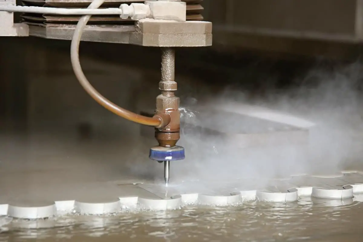
Imagine cutting through steel or marble with nothing more than a jet of water. This is the power of abrasive water jet technology, a groundbreaking method that uses high-pressure water mixed with abrasives to slice through materials without generating heat. In this article, you will discover how this technology works, its applications in various industries, and the science behind its cutting efficiency. Get ready to explore how abrasive water jet cutting is transforming manufacturing and what it means for the future of material processing.
Water jet technology is a new technology developed in the past 20 years and its applications are increasingly widespread. It has been applied in sectors such as coal, machinery, petroleum, metallurgy, aviation, construction, water conservancy, and light industry mainly for cutting, crushing, and cleaning materials.
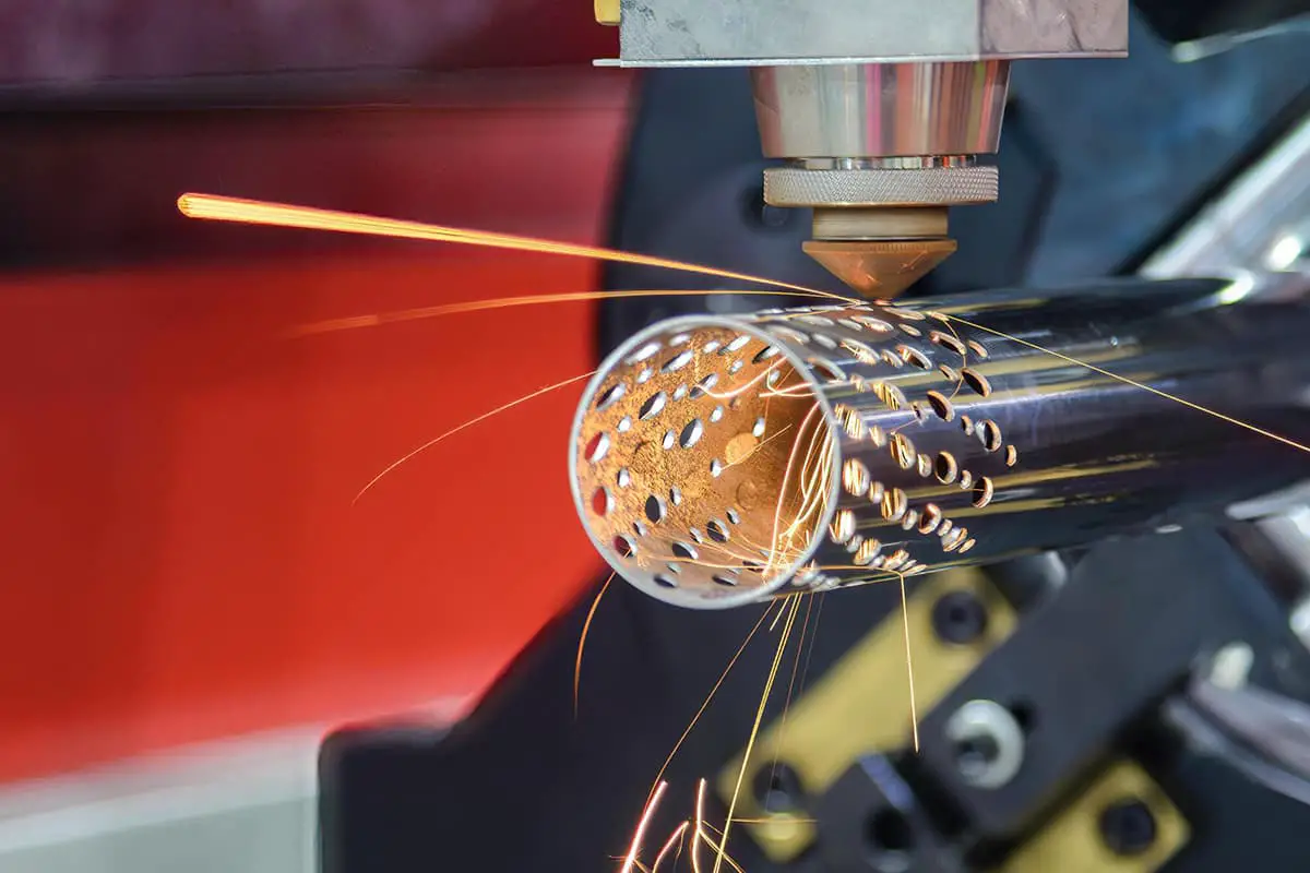
Especially in recent years, with the rapid development of high technology, laser beams, electron beams, plasma, and water jets have become new cutting tools.
Among them, laser beams, electron beams, and plasma belong to thermal cutting processing, while water jet is the only cold processing method. In cutting, crushing and surface pre-processing of many materials, water jet has its unique superiority.
The development of water jet can be roughly divided into four stages:
Exploration and experimental stage: In the early 1960s, low-pressure water jet mining was mainly studied.
Equipment development stage: From the early 1960s to the early 1970s, high-pressure pumps, boosters, and high-pressure fittings were mainly developed, while promoting water jet technology.
Industrial application stage: From the early 1970s to the early 1980s, a large number of water jet mining machines, cutting machines, and cleaning machines appeared successively.
Rapid development stage: From the early 1980s to the present, research on water jet technology has further deepened, and new types of jets such as abrasive jet, cavitation jet, and self-excitation vibration jet have developed rapidly. Many products have been commercialized.
The four stages of development of waterjet cutting.
The fourth stage: Rapid development stage.
The third stage: Industrial application stage
The second stage: Equipment development stage.
The first stage: Experimental exploration stage.
Concept of abrasive waterjet:
Abrasive waterjet is a special processing method that uses water as a medium, obtains tremendous energy through a high-pressure generating device, adds abrasives to the high-pressure water jet through a feeding and mixing device, and forms a two-phase mixture of liquid and solid.
It relies on the high-speed impact and erosion of the abrasive and high-pressure water jet to achieve material removal.
Processing principle of abrasive waterjet:
The processing of abrasive waterjet is based on the principle of hydraulic pressure, which uses a high-pressure generator or a high-pressure pump to pressurize water to ultra-high pressure.
The mechanical performance of the electric motor is converted into pressure energy, and the water with tremendous pressure energy is then transformed into kinetic energy through a small-hole nozzle. This forms a high-speed water jet and creates a certain degree of vacuum in the mixing chamber.
Under the action of its own weight and pressure difference, the abrasive is sucked into the mixing chamber and violently agitated, diffused and mixed with the water jet, forming a high-speed abrasive water jet that impacts the workpiece at an extremely high speed through the abrasive nozzle.
After the abrasive waterjet impacts the workpiece, a high-speed concentrated local stress field is produced on the material, which changes rapidly, leading to erosion, shear, and finally material failure and removal.
In the process of abrasive waterjet processing, the main function is performed by the abrasive particles, and the water jet acts as a carrier to accelerate the abrasive particles.
Compared with pure water jet, the abrasive waterjet has greater kinetic energy due to the larger mass and higher hardness of abrasive particles, resulting in stronger processing effects.
Abrasive water jet device
The abrasive water jet device includes a water supply system, a pressurization system, a high-pressure waterway system, an abrasive supply system, a cutting head device, a receiving device, an actuating mechanism, and a control system as shown in the figure below.
The role of the water supply system is to soften water quality, reduce corrosion of the high-pressure waterway caused by water quality, and improve the working life of the reciprocating seal in the high-pressure system.
The core component of the pressurization system is the pressure intensifier, which generally uses hydraulic reciprocation.
The pressure ratio of the intensifier is usually selected as 10:1 or 20:1, and the output water pressure of the intensifier can be adjusted by changing the oil pressure of the input hydraulic system, which can increase the water pressure to 100-400MPa, and even up to 690MPa and 700MPa. The high-pressure waterway system connects the pressurization system and the cutting head device.
In order to transport high-pressure water and meet the requirements of fast and flexible movement of the cutting head, the high-pressure water pipeline usually uses flexible and ultra-high-pressure resistant stainless steel pipes, and is composed of several rotating pipe joints.
The abrasive supply system includes a hopper, an abrasive flow valve, and a conveying pipe. The pure water jet cutting head includes a high-pressure water switch valve and a jewel nozzle. The abrasive water jet cutting head also includes a mixing chamber and a mixing nozzle that mixes the water jet with the abrasive.
The mixing nozzle requires high wear resistance and is generally made of cemented carbide. The receiving device is placed below the workpiece to collect the remaining abrasive jet, and has functions such as energy absorption, noise reduction, splash prevention, and safety.
The actuating mechanism and control system control the control device of the cutting head’s motion trajectory, and the control methods include manual, motorized, NC, and CNC.
Figure 1.1 Schematic diagram of abrasive water jet special machining technology
Abrasive:
It is generally divided into three categories: mineral-based, metal-based, and artificial.
Selection principle:
(1) Good cutting effect;
(2) Low price and sufficient supply.
Common abrasives include:
Tab.1.2 Several commonly used abrasive
Abrasive Name
Mesh count
Particle size (um)
Purpose
Garnet
40
420
Rough machining
Garnet
50
297
The cutting speed is slightly faster than 80 mesh, but the surface is slightly rough
Garnet
80
178
Most commonly used general purpose
Garnet
120
124
Produce a smooth surface
Quartz sand
Ideal sandblasting and rust removal abrasive for steel surfaces
alumina
Polishing supplies
Nozzle:
It consists of a water jet nozzle, a mixing chamber, and an abrasive jet nozzle.
Classification:
(1) According to the number of water jets: single jet nozzle, multi-jet nozzle
(2) According to the method of abrasive input: abrasive-side feed nozzle, abrasive-middle feed nozzle, abrasive-tangential feed nozzle.
1. Single jet abrasive side feed nozzle
Single Abrasive Jet Side-Feed Nozzle
Mixing Chamber
Abrasive Jet Nozzle
Water Jet Nozzle
Advantages: Simple structure, good concentration and stability of the jet.
Disadvantages: Poor mixing effect between abrasive and water.
2. Single jet abrasive tangential feed nozzle
Single Abrasive Jet Tangential Feed Nozzle
Water Jet Nozzle
Abrasive Jet Nozzle
The abrasive and water jet are fully mixed, while reducing mutual collision between abrasives, thereby improving the cutting ability of the abrasive jet.
3. Multi-jet abrasive middle feed nozzle
Multi Abrasive Jet Center-Feed Nozzle.
It is mostly used for abrasive jet cleaning or rust removal.
4. Abrasive jet nozzle with a straightening pipe
Abrasive Jet Nozzle with Straightening Pipe
Nozzle Body
Abrasive Inlet
Water Jet Nozzle
Nozzle Base
Seal
Lock Nut
Straightening Pipe
It has a simple structure and is easy to operate. It is widely used in the abrasive jet cutting industry.
Classification of abrasive water jet processing technology:
According to the mixing method of abrasive and water, it can be classified into two types:
Front hybrid abrasive waterjet.
Rear hybrid abrasive waterjet.
Front hybrid abrasive waterjet:
The abrasive and water are evenly mixed into an abrasive slurry water in the high-pressure pipeline, and then the jet formed by the abrasive nozzle is called a front mixed abrasive jet. This mixing effect is good, requiring low pressure, but the device is complex, and the nozzle wears severely.
Rear hybrid abrasive waterjet:
Adding abrasives to the water jet after it is formed is called a rear-mixed abrasive waterjet. The mixing effect is slightly worse, requiring high pressure, but the nozzle wears less. The theoretical research and application technology of the rear-mixed abrasive waterjet are relatively mature, and it has been widely used in many industrial sectors.
Classification of Abrasive Waterjet Machining Technology.
Submerged abrasive waterjet.
Non-submerged abrasive waterjet.
Submerged waterjet refers to the jet being in water from the outlet to the workpiece, which has the characteristics of rapid jet diffusion, uniform distribution of speed and dynamic pressure.
Non-submerged waterjet means that the jet is in the natural state of air from the outlet to the workpiece. Compared with submerged jet, it has a longer range and longer core length, but the speed distribution is not uniform.
2. Cutting mechanism and cutting law of abrasive waterjet.
Cutting mechanism of abrasive waterjet:
When cutting a target material with an abrasive waterjet at a certain jet traverse speed, a part of the water jet shoots towards the target material at a constant speed while another part weakens its cutting force as it penetrates deeper into the material.
As a result, the cutting surface appears to bend in the opposite direction of the jet traverse, as shown in Figure a below. The angle between the axis of the bent cutting surface and the original jet axis gradually increases from where the jet enters the target material, and the jet deflects more and more along the opposite direction of the traverse.
However, due to the large inertia of the abrasive particles themselves, they do not deflect with the water jet carrier, leading to the separation of the abrasive particles from the water jet and the local concentration erosion of the abrasive particles.
The larger the acceleration of the abrasive particles, the greater the refracted angle upon separation, and the more severe the concentration erosion. The local concentration erosion of the abrasive particles causes a significant increase in the grinding amount along the cutting surface, forming a step on the cutting surface.
Therefore, during the erosion that forms the step, the deflection angle of the water flow above the step increases continuously, the deflection of the water jet from the cutting surface increases, and the grinding amount below the step decreases until the upper step becomes perpendicular to the original jet direction, as shown in Figure b below.
As the jet traverse continues, the cutting surface returns to smooth cutting and grinding, as shown in Figure c below. From this point on, the cutting cycle begins again with the transition from smooth cutting and grinding to deformation erosion and grinding.
During this process, the entire cutting surface continues to transform into an interval of travel, and because the deflection of the abrasive waterjet approximates an arc, it forms a cutting cross-section with a wave-like interval along the direction of the jet traverse.
Figure 9-32 Abrasive Jet Cutting Process Model
a- The cutting surface may become bent due to the smooth cutting and grinding process.
b- The formation stage of the cutting surface is mainly due to erosion, deformation, and grinding.
c- The cutting surface is transformed back into a smooth cutting and grinding surface along the feed direction.
Mathematical model of abrasive waterjet machining:
M. Hashish, based on the solid particle erosion theory of Finnie and Bitter, and a series of visualization experiments, proposes that the process of material removal by an abrasive waterjet consists of two regions: cutting wear and deformation wear, as shown in the figure below.
In the cutting wear region, that is, before the cutting depth reaches hC, the abrasive particles impact the material at a small angle, and the material is removed in a micro-cutting mode. When the cutting depth reaches hC, the impact velocity of the abrasive particles on the material decreases, and the material removal mode changes.
The abrasive particles impact the material at a large angle, and the material is removed in a deformation wear mode.
On this basis, M. Hashish obtains the mathematical models for the cutting depth in the cutting wear region and the cutting depth in the deformation wear region:
where
hc is the cutting depth (mm) for the cutting wear mode;
hd is the cutting depth (mm) for the deformation wear mode;
Ck is the characteristic velocity (m/s);
dj is the jet diameter (mm);
m is the mass flow rate of abrasive particles (g/s);
Ve is the critical velocity (m/s) of the abrasive particles;
Vo is the initial velocity (m/s) of the abrasive particles;
ρp is the density (g/cm3) of the abrasive particles;
u is the traverse speed (mm/s) of the nozzle;
Cf is the friction coefficient;
σ is the shear stress (MPa).
This model includes almost all the parameters involved in abrasive waterjet machining. However, some parameters such as Vo and Ve need to be determined experimentally. Therefore, the results obtained by different operators may vary.
Factors affecting the cutting performance of abrasive waterjet:
As abrasive waterjet cutting is a very complex process, there are many parameters that can affect its cutting performance.
These parameters include dynamic parameters (water nozzle diameter, water pressure), abrasive parameters (abrasive material, size, flow rate), abrasive nozzle parameters (abrasive nozzle diameter, length, material), cutting parameters (cutting speed, standoff distance, impact angle, number of cuts), workpiece parameters (hardness), and so on. However, the process parameters that are easy to control mainly include water pressure, abrasive parameters, cutting speed, and standoff distance.
The main indicators for evaluating cutting performance include cut depth, kerf shape (width of upper and lower parts of the kerf and kerf taper), and surface quality (roughness and waviness).
Cutting laws of abrasive waterjet:
(1) The cutting depth increases with the increase of water pressure, abrasive hardness, and number of cuts, while it decreases with the increase of cutting speed. There is an optimal value relationship between cutting depth, standoff distance, abrasive supply, and abrasive particle size. As the cutting depth increases, the peak height and deflection angle of the striations on the cutting section gradually increase, while the frequency of occurrence of the striations decreases.
(2) The kerf width has an optimal value relationship with cutting speed, and the optimal cutting speed is about 1/5 of the maximum cutting speed. In a single cut, the cutting speed is determined by the material properties, thickness, and section quality requirements. When the traverse speed is constant, the higher the pressure, the smoother the cutting surface; when the surface roughness is the same, the higher the pressure, the higher the traverse speed.
(3) With the increase of jet pressure or the decrease of cutting speed, the quality of the cutting section is significantly improved. Compared with brittle materials, the cutting section of plastic materials is smoother, and its morphology is more affected by jet pressure and cutting speed.
(4) The cutting area velocity of abrasive waterjet decreases with the increase of material fracture energy value, increases with the increase of pressure, and decreases with the increase of standoff distance. There is an optimal value relationship between cutting area velocity and abrasive supply. When the traverse speed and material thickness are constant, there is an optimal standoff distance value that results in the deepest cutting depth. As the standoff distance increases, the groove width gradually increases. When the pressure is constant, the smaller the traverse speed, the deeper the cutting depth.
3. Current Research Status of Abrasive Water Jet Machining Technology.
Abrasive water jet cutting.
M. Hashish is one of the earliest researchers to study abrasive water jet machining. Through experimentation with abrasive water jet cutting, he found that it can be used to cut felt, ceramics, metals, glass, graphite sintered composites without delamination.
Additionally, he noted that there is no thermal stress or deformation stress in the cutting zone. He also discussed the effect of different cutting parameters on material processing performance and material removal rate, and pointed out that optimizing cutting parameters will greatly improve cutting performance.
Since then, a large amount of domestic and foreign research and application of abrasive water jet machining has mainly focused on cutting. The schematic diagram of abrasive water jet cutting and the cross-section of the sample after cutting are shown in Figure 3.
Schematic diagram and machining diagram of abrasive water jet cutting, as well as sample cross-section of abrasive water jet cutting
From a micro perspective, the essence of abrasive water jet cutting is the cumulative effect of a large number of abrasive particles micro-cutting the workpiece material. The key issue that needs to be solved is the control of the cutting edge shape and cutting depth.
The development and improvement of the key equipment of abrasive water jet cutting and the mathematical model of precise cutting mechanism enable this technology to cut metal materials with a thickness of 100-200 mm and hard brittle materials with a thickness of about 50 mm.
However, during the abrasive water jet cutting process of thick structural components, the jet beam will produce a “tail flicking” phenomenon due to energy attenuation, as shown in Figure 4.
The smooth cutting area is located at the upper edge of the incision. The closer it gets to the bottom of the workpiece, the more obvious the “tail flicking” phenomenon becomes, which greatly affects the surface roughness, shape, and positional accuracy of the cut workpiece.
By optimizing the cutting process and using swing cutting head technology with tolerance controllers, intelligent compensation can be made for the cutting accuracy of the incision, thereby improving the processing quality.
Abrasive water jet milling
The method of controlling abrasive water jet machining parameters to remove only the surface material of the workpiece without penetrating it is called abrasive water jet milling. The machining schematic and product are shown in Figure 5.
Figure 5 Schematic diagram of sleeping material water jet milling and abrasive water jet milling sample
Although this technology is still in the experimental research stage, many researchers have studied the mechanism and process of this new abrasive water jet machining technology.
In terms of abrasive water jet milling of plastic materials, M. Hashish and others proposed the feasibility of abrasive water jet milling and found that the nozzle traverse speed is an important parameter affecting milling uniformity.
Hocheng H studied the feasibility of abrasive water jet milling fiber-reinforced plastics. By studying the debris formation mechanism of single milling, double milling, and multi-milling, they predicted that deformation wear is the main cutting mechanism for milling fiber-reinforced plastics. They also analyzed the effects of jet pressure, target distance, nozzle traverse speed, and abrasive flow rate on material removal rate, milling depth, and milling width.
Fowler and Shipway studied the surface characteristics of materials milled by abrasive water jet and pointed out that high nozzle movement speed, fine particle abrasives, low jet pressure, and small erosion angles can obtain milling surfaces with smaller waviness. Paul et al. studied the effect of different milling parameters on the groove depth and material removal rate of abrasive water jet milling and established an empirical model using regression analysis.
There is less research on abrasive water jet milling of hard and brittle materials. Zeng JY studied the effect of jet impact angle on abrasive water jet milling of polycrystalline ceramics, and found that the optimal material removal rate can be obtained when the jet angle is 90 degrees during milling impact. They also established and verified a mathematical model of erosion rate.
Abrasive water jet drilling can be divided into two processing methods: bushing and drilling. Bushing is the process of cutting the material along a circular curve to form a larger diameter hole. This process evolved from contour cutting of abrasive water jet, as shown in the following figure (hole #9).
Figure 6 Schematic diagram of abrasive water jet drilling and sample of abrasive water jet drilling
Drilling is the process of machining smaller diameter holes without holes, as shown in the right figure (holes #3-#8). Guo Z et al. studied the machining mechanism and process of abrasive water jet drilling of ceramic materials such as A12 O3, Si3 N4, and SiC, and concluded that material removal is mainly achieved through micro-fracturing, micro-cutting, and erosion.
Yong Z et al. established the relationship between the depth of abrasive water jet drilling and process parameters based on chaotic phenomena in erosion processes. Xing Xizhe introduced different hole processing methods for abrasive water jet and pointed out the many advantages of abrasive water jet drilling, including drilling holes in hard and brittle materials and laminated composite materials that can drill deep holes, small holes, and irregular holes without thermal impact zone, obtaining higher dimensional accuracy and lower surface roughness, and easily achieving hole processing on inclined surfaces.
Abrasive water jet turning.
Abrasive water jet turning is similar to single-point cutting on a conventional lathe, using the rotation of the workpiece and the linear or curvilinear motion of the cutting head to remove material from the workpiece. The machining schematic and product are shown in Figure 7. The advantages of abrasive water jet turning include low cutting force, no thermal damage to the workpiece, and fine chips without chip-breaking problems.
Figure 7 Schematic diagram of abrasive water jet turning and sample of abrasive water jet turning
M. Hashish first proposed the concept of abrasive water jet turning in 1987 and pointed out that abrasive water jet can be used to turn special difficult-to-machine materials such as carbon/metal composites, glass, and ceramics to obtain complex shapes.
Ansari et al. demonstrated that abrasive water jet turning is superior to conventional lathe turning for difficult-to-machine materials, with speeds 5-10 times faster for machining SiC ceramics. Zhang ZW studied the effect of process parameters on surface quality when abrasive water jet turning glass and found that optimal surface quality can be achieved at low nozzle traverse speeds. Manu et al. studied the effect of nozzle inclination angle on product shape during abrasive water jet turning.
Abrasive water jet and other machining methods.
In addition to the abrasive water jet machining technology described above, researchers both domestic and abroad have conducted some research and reported on composite machining techniques using abrasive water jets.
For example, micro abrasive-jet guided laser micro-machining is a composite machining technology of water jets and lasers that fully utilizes the characteristics of water jet technology and effectively solves problems such as the small effective processing range and thermal effects in traditional laser processing, which makes it have broad application prospects in the field of micro-machining; ultrasound-assisted abrasive water jet machining is a feasible and efficient brittle material processing method that combines water jets with ultrasonic waves; water jet shot peening is a new type of surface treatment method for improving the fatigue life of metal components through cold working processes, which has advantages such as high peening strength, low peening pressure, and good strengthening effect.
4. Characteristics, Applications, and Development of Abrasive Water Jet Machining Technology.
Advantages of abrasive water jet machining include:
Compared with pure water jets, abrasive jets greatly reduce the pressure required for cutting under the same cutting purpose, highlighting the advantages of safety and reliability.
When cutting metal with abrasive water jets, sparks are generally not generated, avoiding ignition or explosion accidents of harmful gases near the cutting area.
During cutting, little or no heat is generated, and any heat generated can be quickly taken away by the water jet, resulting in almost no heat-affected zone on the cutting surface.
The cutting force on the cutting surface is small, so even when cutting thin sheet into shaped parts, the cutting edge will not be damaged.
The cut is narrow, the material loss is small, the cut surface is smooth, and there are no burrs (a small amount of burrs may be produced if the cutting speed is too fast).
There is almost no dust during cutting, and no toxic gas is generated, making the working conditions relatively clean.
The cutting reaction force is small, so the nozzle can be easily moved by a mechanical arm.
All-round cutting is possible, and cutting of three-dimensional curved surfaces is easy, making it possible to cut workpieces of various shapes.
Cutting conditions are easy to control, facilitating automatic adjustment and control using computers.
Disadvantages of abrasive water jet machining include:
The equipment requires high power.
The nozzle wears quickly.
It is not suitable for processing large parts or for removing very large burrs.
There is a lack of software specifically designed for water jet machining.
Applications of abrasive water jet technology include:
Aerospace industry: Cutting special materials such as aluminum alloy, honeycomb structures, carbon fiber composites, layered metals, or reinforced plastic glass, cutting aircraft blades with water jets without heat-affected zones and work hardening, eliminating the need for subsequent processing.
Automotive manufacturing and repair industry: Cutting various non-metallic materials and composite components such as dashboards, carpets, asbestos brake pads, door frames, car roof glass, interior decoration boards, rubber, plastic gas tanks, and other internal and external components.
Weapon industry: Cutting armor plates, tracks, bulletproof glass, vehicle bodies, turrets, guns, and safe dismantling of various scrap shells.
Forestry, agriculture, and municipal engineering: Used for logging, bark stripping, irrigation, feed processing, road maintenance, cutting crafts and other tasks.
Electronics and power industry: Can be used for shaping and cutting printed circuit boards and thin films, computer hard disks, floppy disks, electronic components, amorphous alloys, transformer cores, and special cables that are difficult to cut by conventional methods.
Machinery manufacturing industry: Using high-pressure water cutting instead of punching and shearing processes can not only save mold costs but also reduce noise, vibration and improve material utilization. In addition, it can remove external alumina on workpieces, sand cores on castings, ceramic coatings, cutting burrs, gate risers, and other parts, and can also cut grey iron parts that are difficult to cut by conventional methods.
Other industries: Cutting marble, granite, floor tiles, ceramics, etc. in the building decoration industry, processing finished paper rolls, toilet paper, etc. in the paper industry, and processing plywood, wooden boards, etc. in the wood industry.
The development prospects of abrasive water jet machining technology are:
Improving the reliability and service life of water jet machining, especially the service life of key components such as high-pressure pumps, high-pressure hoses, joints, and nozzles.
Optimizing process parameters to further improve efficiency, reduce abrasive consumption, and lower energy consumption, making costs more competitive.
Developing intelligent control to enable process parameters to be adaptively adjusted during processing, improving machining accuracy, and used for manufacturing parts with certain precision requirements, achieving a technical and economic effect that can be comparable to plasma and laser machining.
Development trends of Abrasive Water Jet Machining Technology:
Continuously expanding the application scope of water jet machining, from 2D cutting and deburring to hole machining and processing of 3D surfaces.
Theoretical research on water jet machining, especially the establishment of models for water jet machining and the study of multiphase flow theory.
Research on the machining of miniature precision parts using abrasive water jet technology, as well as the use of abrasive water jet for turning and milling.
As the founder of MachineMFG, I have dedicated over a decade of my career to the metalworking industry. My extensive experience has allowed me to become an expert in the fields of sheet metal fabrication, machining, mechanical engineering, and machine tools for metals. I am constantly thinking, reading, and writing about these subjects, constantly striving to stay at the forefront of my field. Let my knowledge and expertise be an asset to your business.
Imagine a cutting technique so precise it revolutionizes the production of essential motor and transformer components. Water cutting of silicon steel sheets does just that, offering superior quality and efficiency.…
Ever wondered what it really costs to operate a waterjet cutting machine? This article breaks down the total expenses, including equipment depreciation, consumables, and labor, offering a comprehensive guide to…
In the rapidly evolving world of manufacturing, cost-cutting is king. Waterjets have emerged as a game-changer, offering unparalleled versatility and efficiency. But how can you harness their full potential to…
Have you ever wondered how manufacturers achieve precision and efficiency when cutting stainless steel? This article dives into six advanced techniques for stainless steel cutting, highlighting their benefits and applications.…