Press Brake Operation Manual (Training PDF)
Attention all mechanics and engineering enthusiasts! Have you ever wondered about the ins and outs of operating a press brake machine? In this blog post, we'll dive into the world…
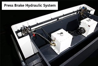
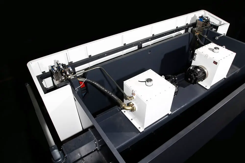
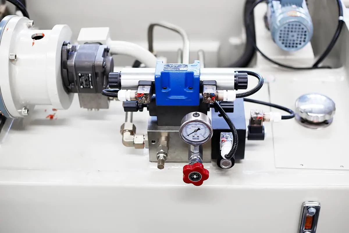
Have you ever wondered how a press brake’s hydraulic system works? In this article, we’ll dive deep into the intricacies of this essential component. Our expert mechanical engineer will guide you through the system’s key elements, explaining their functions and interactions. By the end, you’ll have a comprehensive understanding of how hydraulics power these impressive machines.
Composition of hydraulic system
Powerplant
Hydraulic Pump: The mechanical energy input by the prime mover is converted into the pressure energy of the liquid, which serves as an energy supply device for the system.
Actuator
Hydraulic Cylinder (or Motor): Converts fluid pressure energy into mechanical energy and performs work on the load.
Control device
Various hydraulic control valves are used to control the direction, pressure, and flow of the fluid to ensure the actuator completes the intended work task.
Assisting equipment
The fuel tank, oil pipes, oil filters, pressure gauges, coolers, water separators, oil misters, mufflers, pipe fittings, pipe joints, and various signal converters create the necessary conditions to ensure the normal operation of the system.
Working medium
Hydraulic oil or compressed air, as a carrier to transfer motion and power.
Oil tank
The function of the fuel tank:
Structure of the fuel tank:
Fuel tank size (volume) – V = 3-5q for fixed equipment; V≈1q for walking equipment.
The unit of V is liter, and the unit of q is liter/minute.
When designing the fuel tank, there should be 10-15% space in the upper part of the fuel tank, mainly considering factors such as liquid level changes and foam.
The effective volume of the fuel tank should be 6-12 times the total flow of the hydraulic system’s oil pump.
The oil temperature is recommended to be 30-50°C, with a maximum temperature not exceeding 65°C and a minimum temperature not lower than 15°C.
The bulkhead should be designed in the fuel tank, and the distance between the oil suction area and the oil return area should be as far as possible.
Hydraulic oil
It is very important for the perfect function, operational reliability, life and economy of the hydraulic system.
The important concept of oil
Cleanliness
Viscosity standard: The viscosity value is always related to a certain temperature. The viscosity value decreases as the temperature increases and increases as the pressure of the hydraulic oil increases. The viscosity standard is ISO standard at 40 ℃, which can be divided into #10, #22, #32, #46, #68, #100 hydraulic oil.
Oil pollution degree standards: International ISO-4406 and American NAS-1638. At the NAS9 level, the hydraulic system generally does not fail. When the pollution level drops to NAS10-11 level, the hydraulic system will occasionally fail. When the pollution degree of the oil drops below the NAS12 level, faults often occur. At this time, the hydraulic oil must be circulated and filtered.

According to function, it can be divided into:
According to the installation method, it can be divided into:
According to the control method, it can be divided into:
Directional valve
The basic function of the directional valve is to facilitate the communication and cut-off between two different hydraulic circuits, or to control the direction of starting, stopping, and movement of the actuator (cylinder or motor) as required.
Classification of directional control valves
Divided by control method:
Divided by installation method:
Relief valve
Features
The most important function of the relief valve is to limit the system pressure, thereby protecting various components and pipelines and preventing the danger of overload and bursts.
This valve is therefore also called a pressure valve or a safety valve.
When the system pressure reaches the set pressure value, the relief valve starts to act as a pressure limiter.
The originally closed valve is now opened, and the excess flow flows back to the tank through the valve port.
When working in this way, the relief valve is installed on the bypass.
It should be noted that the power relief loss of flow Q with pressure P passing through the relief valve is P×Q/612.
The lost energy is transmitted to the hydraulic system, which causes the temperature of the hydraulic oil to rise.
Fundamental
The inlet pressure P acts on the measurement area A, and the resulting hydraulic pressure is compared with the spring force.
If the hydraulic pressure exceeds the set force of the spring, the valve core compresses the spring and the valve port opens, connecting the path between the valve inlet and outlet.
Flow valve
The flow valve controls the speed of the hydraulic actuator.
This is accomplished by changing the size of the cross-sectional area of the throttle to alter the volume flow rate Q of the actuator.
The flow valve can be divided into the throttle valve and speed control valve.
Check valve
The function of the check valve is to cut off flow in one direction and allow flow in the other direction to pass without restriction.
One-way valve sealing elements have spherical, cone-valve, or plate-valve forms.
The relatively weak spring force needs to be overcome when the sealing element is opened.
These basic principles are directly reflected in the graphic symbols.
Two-way cartridge valve
The two-way cartridge valve is designed as a plug-in structure and is installed in a compact control circuit.
In most cases, the cover plate also functions as a connection block between the main valve and the pilot valve.
By controlling the main valve with a suitable pilot valve, pressure, reversing or throttling functions, or a combination of these functions can be achieved.
The functions include directional control, overflow control, decompression control, and sequence control.
Proportional valve
Open-loop proportional valve – electro-hydraulic proportional valve
Closed-Loop Proportional Valve – Proportional Servo Valve
Proportional servo valve
Frequency response: 120Hz
Hysteresis: 0.1%
No dead zone (zero cover)
Automatic compensation without balancing valve
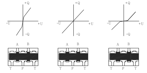
If there is no feedback between the output and input of the system, meaning that the output of the control system does not affect the control of the system, such a system is called an open-loop control system.
Closed-loop control system:
The closed-loop control system is an automatic control system based on the principle of feedback.
The feedback principle means controlling according to the information of the system output change. That is, comparing the deviation between the system behavior (output) and the expected behavior and eliminating the deviation to obtain the expected system performance.
In the feedback control system, there is both a signal forward path from the input to the output and a signal feedback path from the output to the input.
The two form a closed loop.
Therefore, the feedback control system is also called a closed-loop control system.
The open-loop control system has a simple structure and is relatively economical.
The disadvantage is that the error caused by interference cannot be eliminated.
Compared with the open-loop control system, the closed-loop control system has a series of advantages.
In the feedback control system, no matter the reason (external disturbance or internal change of the system), a corresponding control effect will be generated to eliminate the deviation as long as the controlled quantity deviates from the specified value.
Therefore, it has the ability to suppress interference, is insensitive to changes in component characteristics, and can improve the response characteristics of the system.
However, the introduction of a feedback loop increases the complexity of the system, and improper gain selection can cause system instability.
To improve control accuracy, control by disturbance (that is, feedforward control) is often used as a supplement to feedback control to form a composite control system when the disturbance variable can be measured.
| Open-Loop Proportional Valve | Closed-loop servo valve |
| Frequency response: 15Hz | Frequency response: 120Hz |
| Hysteresis: 5% | Hysteresis: 0.1% |
| Reverse error: 1% | Reverse error: 0.05% |
| Repeat accuracy: 0.1 | Repeat accuracy: 0.01 |
| Median dead zone | Zero cover |
Pressure control
Start the oil pump motor. According to the required bending force, the proportional pressure valve (4) controls the two-way cartridge valve (2) to adjust the pressure of the hydraulic system to meet the bending force requirements.
The pressure valve (4.1) is a safety valve that controls the maximum pressure of the system.
Work cycle
Hurry down
Apply a 1Y1 voltage (20% ~ 30%) to the proportional pressure valve (4), and 1Y2 solenoid valve (6) loses power. When solenoid valve (5) 4Y3 is energized, it gives a positive voltage to the proportional servo valve.
As the slider weight rapidly decreases, oil is drawn into the upper cavity of the cylinder through the flow valve, and oil discharged from the oil pump enters the upper cavity of the cylinder through the proportional servo valve (2).
The oil in the lower chamber of the cylinder is returned to the tank through solenoid valve 5 (A-P) and proportional servo valve (2) (B → T).
The fast down speed of the slider can be obtained by adjusting the control voltage of proportional servo valve 4Y5 to control the opening of the proportional servo valve to obtain different speeds.
Work progress
The proportional pressure valve (4) 1Y1 is energized, the electromagnetic reversing valve (6) 1Y2 is energized, the filling valve is closed, the solenoid valve (5) 4Y3 is de-energized, and the pressure oil discharged from the oil pump passes through the proportional servo valve (2) and enters the upper cavity of the cylinder (no rod cavity).
The oil in the lower chamber of the cylinder returns to the oil tank through the backpressure valve (4) and the proportional servo valve (2) while the slider is pressed down.
By adjusting the control voltage 4Y5 of the proportional servo valve, different working speeds are obtained by controlling the opening of the proportional servo valve.
The safety valve (3) prevents the pressure in the lower cavity of the oil cylinder from becoming too high, and the set pressure is 10% higher than the system pressure.
The setting pressure of the backpressure valve (4) is generally the equilibrium pressure plus (30 ~ 50) bar.
Hold pressure
When the ram reaches the bottom dead point, the proportional servo valve 2 (4Y5) is 0V to cut off the path of the upper and lower chambers of the cylinder, and the slider stops at the bottom dead point.
Unloading
After the pressure maintenance of the press brake machine is complete, the proportional pressure valve maintains the pressure, and the system gives the proportional servo valve 2 (4Y5) a certain negative voltage, so that the proportional valve is slightly opened (return direction).
At the same time, the ram will also move up a small amount, and the amount is set by the unloading distance parameter.
The time taken for the unloading process is set by the decompression speed parameter.
The pressure in the upper cavity of the cylinder is released through the proportional servo valve (2).
Return
When solenoid valve (6) 1Y2 loses power, a certain voltage is applied to the proportional pressure valve (4), the solenoid valve (5) 4Y3 loses power, and the proportional servo valve (4Y5) has a negative voltage.
The pressure oil is passed from the pump block through 2 synchronization blocks.
The hydraulic oil is directed from the upper proportional servo valve (2) and the electromagnetic reversing valve (5) (P-A) to the lower chamber of the cylinder (with a rod chamber), and the upper chamber of the cylinder (without a rod chamber) is returned to the tank through the filling valve.
The ram returns quickly.
The return speed can be obtained by adjusting the control voltage of the proportional servo valve 4Y5 to control the opening of the proportional servo valve (2) to obtain different speeds.
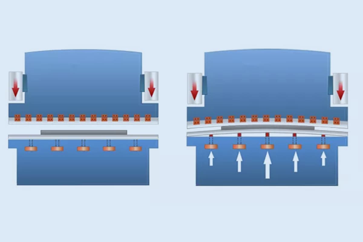
Workbench compensation
The compensation of the workbench is achieved by controlling the proportional pressure reducing valve (10) 1Y3.
The pressure oil enters the compensation cylinder through the proportional pressure reducing valve (10), and the pressure of the proportional pressure reducing valve is adjusted by changing the voltage of the proportional pressure reducing valve (10).
This is done to make the table convex and compensate for the deformation of the table during bending.
System without pressure
Check whether the plug on the proportional pressure valve (04) is loose, whether there is a corresponding electrical signal in 1YI, and whether the safety valve (4.1) is loose.
Check whether the spool of the two-way cartridge valve (02) is stuck and whether the fluid resistance (09) installed on the spool is blocked. Also, check whether the spool of the proportional pressure valve (04) is stuck.
Open the fuel tank cover and check the oil return condition of the oil return port if the set pressure cannot be reached. If there is no oil return or the oil return flow rate is not urgent, the oil pump is damaged and needs to be replaced.
Ram down
First, check whether the pressure of the back pressure valve and safety valve has decreased.
Stop the ram at the upper starting point and remove the proportional servo valve on the synchronizing block. Observe whether there is any oil overflow from the A port of the proportional servo valve on the valve block. If the oil overflows, the sync block is leaking. Otherwise, there is a leak in the cylinder. Alternatively, reverse the left and right sync blocks. If the sliding phenomenon does not follow the sync blocks, then there is a leak in the cylinder.
Clean the back pressure valve spool. If the problem persists, clean the poppet valve and safety valve.
If the ram slides in one section and not in other sections, this is because the cylinder is not well sealed in one section.
The ram is not fast down, fast down is slow and fast down is not synchronized.
Check whether the plug on the poppet valve on the sync block is loose and whether there is a corresponding electrical signal. Check whether the proportional servo valve power-on signal is given and feedback consistent. If not, it means that the proportional servo valve spool is stuck and must be cleaned.
Check whether the fluid resistance 6 in the X port on the sync block is blocked, and verify whether the filling valve under the sync block is stuck.
Check if the ram rail or cylinder is too tight.
The ram is in fast down but without no work progress
In the diagnostic state, provide the corresponding electrical signals to the proportional servo valve (2), the proportional pressure valve (04), and the electromagnetic directional valve (06). Close the filling valve and adjust the corresponding opening direction of the proportional servo valve. If the cylinders on both sides cannot be driven, check whether the plug 1Y2 on the electromagnetic reversing valve (06) on the pump block is loose, whether there is a corresponding electrical signal, and whether the valve core is stuck. If a certain cylinder cannot be driven, check whether the fluid resistance (6) in the synchronizing block on the cylinder is blocked, and whether the filling valve under the synchronizing block is stuck.
The ram quickly turns down and enters the middle pause
The ram cannot return, or the return speed is too slow
In the diagnostic state, check whether there is pressure in the hydraulic system.
In the diagnostic state, provide the corresponding electrical signals to the proportional servo valve, the proportional pressure valve, and the electromagnetic directional valve simultaneously. Open the filling valve and adjust the corresponding opening direction of the proportional servo valve. For example, if the cylinders on both sides cannot return normally and quickly, check whether the electromagnetic directional valve on the pump block has the corresponding electric signal and whether the valve core is stuck. If a cylinder cannot return normally and quickly, check whether the fluid resistance in the synchronizing block on the cylinder is blocked and whether the filling valve under the sync block is stuck.
Check whether the power-on signal of the proportional servo valve is consistent with the feedback. If not, it means that the spool of the proportional servo valve is stuck and needs to be cleaned.
The oil temperature rises too fast, the system pressure is too high when the oil pump is running dry, and the motor is easy to trip
When the oil pump is running dry, the system pressure is generally about 1 MPa. If the pressure is too high, check whether the fluid resistance (8) of the Y port on the pressure control cover is blocked.
When the machine’s oil pump is running dry, there is no pressure in the system, but the oil temperature rises rapidly. Pollutants in the oil, oil tank, or pipeline can block the filter element, and the oil filter element needs to be replaced.
Check whether the working distance is too long or the holding time is too long.
Verify whether the piping configuration of the hydraulic system of the machine tool is reasonable.
Exhaust
Fully release the safety valve (014) on the top valve group of the cylinder. Then, enter the DELEM system diagnostic interface and offset the valve by about 40%. The corresponding speed should be about 700 revolutions, and the torque setting value should be about 80DA. Set each run for 5-10 minutes, then close the safety valve.
Precautions
When closing the safety valve, a pressure gauge should be used to adjust the pressure in the lower chamber to 20 MPa. If a pressure gauge is not available, fully tighten the safety valve and then loosen it once. After the exhaust is completed, noise may occur in the first few actions, and the return stroke may not occur. Synchronization and slow return problems are caused by air in the machine pipe and cylinder that has not been completely exhausted.
Generally, the machine will operate normally after 5-8 cycles. If the machine tool’s exhaust is completed and it still cannot return, the lower chamber safety valve needs to be released to exhaust according to the above operation. Do not use automatic parameter search repeatedly or forcefully complete the return stroke to avoid damaging the oil pump.
During initial commissioning, the speed of the fast return stroke should be controlled within 100 mm/s to avoid damage to the oil pump due to lack of air discharge and high speed.
Pressure adjustment
Lower cavity safety valve: The factory setting of the lower cavity safety valve is 20MPa, and it does not need to be adjusted if not necessary.
Backpressure valve adjustment: First, observe the static back pressure of the machine, which is usually around 4-5 MPa, and then add 3-4 MPa to this value as the dynamic back pressure of the machine.
The backpressure valve can be adjusted according to the actual working conditions of the machine.
Slide the ram to the bottom
Enter the DELEM diagnosis interface, offset the two valves by 20%, set the pressure valve (torque) DA value to about 80DA, and then open the quick-release valve. The ram will slowly drop until it reaches the lower mold.
Precautions
The adjustment pressures of the backpressure valves on both sides should be basically the same. Excessive errors will cause problems such as asynchronous work.
When sliding the ram to the end, be sure to apply torque; otherwise, the ram will fall quickly and hit the mold or the bottom of the cylinder, which can cause unpredictable danger.
Significant energy savings, improved efficiency, and 70% reduction in energy consumption.
Use pump control instead of conventional valve control to eliminate throttling losses.
Optimize the precise distribution of the required oil quantity by dynamically adjusting the speed of the servo motor.
Less useless power consumption: turn off the motor when flow or pressure is not needed.
Positive impact on the environment and reduced usage costs.
Reduced power consumption and CO2 emissions.
Reduced installation capacity: the servo motor can be significantly overloaded in a short time, and the actual installation power is only 50% of the theoretical installation power.
Reduce fuel tank volume by 50% and use less hydraulic oil.
Low thermal equilibrium temperature, no cooling device required, and long life of hydraulic components.
Noise reduction: significantly reduced noise under idle, fast down, pressure holding, and returning conditions, improving the working environment.
Improved safety and economy.
Servo motor brakes faster than ordinary motors, and pressure and flow are quickly cut off in emergency situations.
Reduced oil particle sensitivity from NS7 (proportional servo valve) to NS9 (plunger pump), temperature sensitivity is reduced, proportional servo operating temperature is 20 ℃ -50 ℃, servo motor 10 ℃ -80 ℃, plunger pump 20 ℃ -90 ℃.
Excellent speed control performance.
High speed matching. The same valve group is equipped with three pumps of 6, 8, and 10, covering 30-300 tons of bending machine.
Fastest speed of fast down and return up to 200mm/s under certain conditions.
Arbitrary speed can be set within 0-20mm/s.
Outstanding position control performance.
Repeat positioning accuracy of 0.005mm, high-precision bending.
Outstanding track following performance: high synchronization accuracy, within 0.020mm during industrial advance.
Overload protection performance: for different specifications of machine tools, the system provides maximum torque control to prevent human factors from causing system overload.
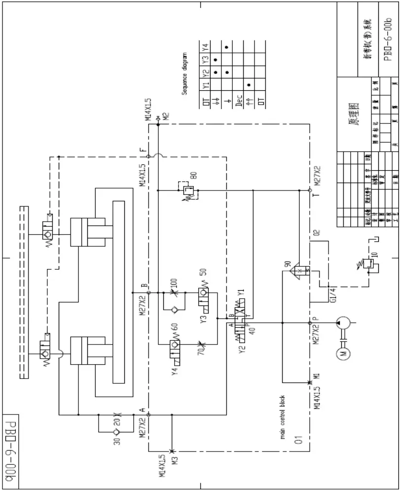
Pressure control
Start the oil pump motor.
Depending on the required bending force, use the remote control valve (10) or proportional pressure valve to control the two-way cartridge valve (90) and adjust the hydraulic system pressure to meet the bending force requirements.
Hurry down
Turn on Y2 and Y3, and turn off Y1.
As the ram’s weight drops rapidly, the filling valve sucks oil into the upper cavity of the oil cylinder.
Additionally, the No. 40 electromagnetic directional valve (P-A) and check valve No. 30 pass oil to the upper cavity of the oil cylinder.
The oil in the lower cavity of the oil cylinder passes through the 100-way one-way throttle valve to the 50-way poppet valve, and then returns to the oil tank through the 40 electromagnetic directional valve (B-T).
Adjust No. 100 one-way throttle valve to control the fast down speed of the slider.
Work progress
Turn on Y2 and Y4, and turn off Y1 and Y3.
The normally closed filling valve (hydraulic check valve) controls the pressure relief of the oil port, and it is closed.
The pressure oil discharged from the oil pump passes through the No. 40 solenoid valve (P → A) and No. 30 check valve to reach the upper cavity of the cylinder.
The oil in the lower cavity of the oil cylinder is returned to the tank through the No. 60 poppet valve, No. 70 throttle valve, and No. 40 solenoid valve (B-T).
Adjust the co-feed speed using the No. 70 throttle valve, and use the M2 port to measure the lower cavity pressure.
Load removal
After the press brake is pressurized, Y1, Y2, Y3, and Y4 are all de-energized, and the pressure oil in the upper cavity of the cylinder passes through the 20th orifice to the 40th electromagnetic directional valve (A → T) to release the pressure. The load removal time is controlled by the time relay.
Return
Y1 is powered while Y2 and Y3 lose power. The pressure oil discharged from the oil pump passes through the No. 40 solenoid valve (P-B), the No. 50 poppet valve, and the No. 100 one-way throttle valve to the lower cavity of the cylinder.
Simultaneously, the pressure oil opens the filling valve (hydraulic check valve).
A large amount of oil in the upper cavity of the oil cylinder is returned to the oil tank through the filling valve.
Ram down
No fast down or slow down
No work progress at speed change point
Cannot return or is slow
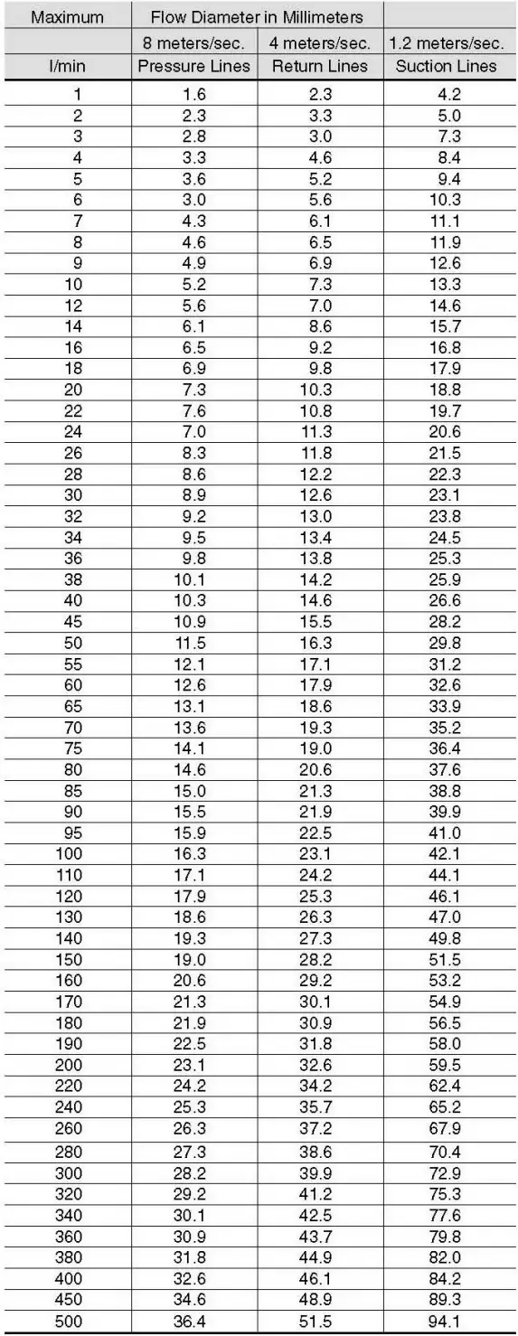
Attached Table 1: Selection of hydraulic pipe diameter
Flow Diameter
Determining Tube Size for Hydraulic Systems
Selecting the proper tube material, type, and size for a given application and fitting type is critical for ensuring efficient and trouble-free operation of the fluid system.
Choosing the right tube material and determining the optimal tube size (O.D. and wall thickness) are essential when selecting proper tubing.
Proper sizing of the tube for various parts of a hydraulic system results in an optimal combination of efficient and cost-effective performance.
A tube that is too small causes high fluid velocity, which can have many detrimental effects. In pressure lines, it causes high friction losses and turbulence, both of which result in high-pressure drops and heat generation.
High heat accelerates wear in moving parts and leads to the rapid aging of seals and hoses, ultimately resulting in reduced component life.
Excessive heat generation also means wasted energy and reduced efficiency.
Selecting an oversized tube increases system cost. Thus, optimum tube sizing is critical. The following is a simple procedure for sizing tubes:
Determine the Required Flow Diameter
Use a table to determine the recommended flow diameter for the required flow rate and type of line.
The table is based on the following recommended flow velocities:

If you desire to use different velocities than the above, use one of the following formula to determine the required flow diameter.
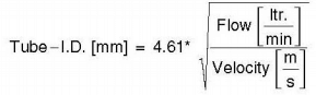
Appendix: Schematic Diagram Of Electro-Hydraulic Servo Press Brake Hydraulic System
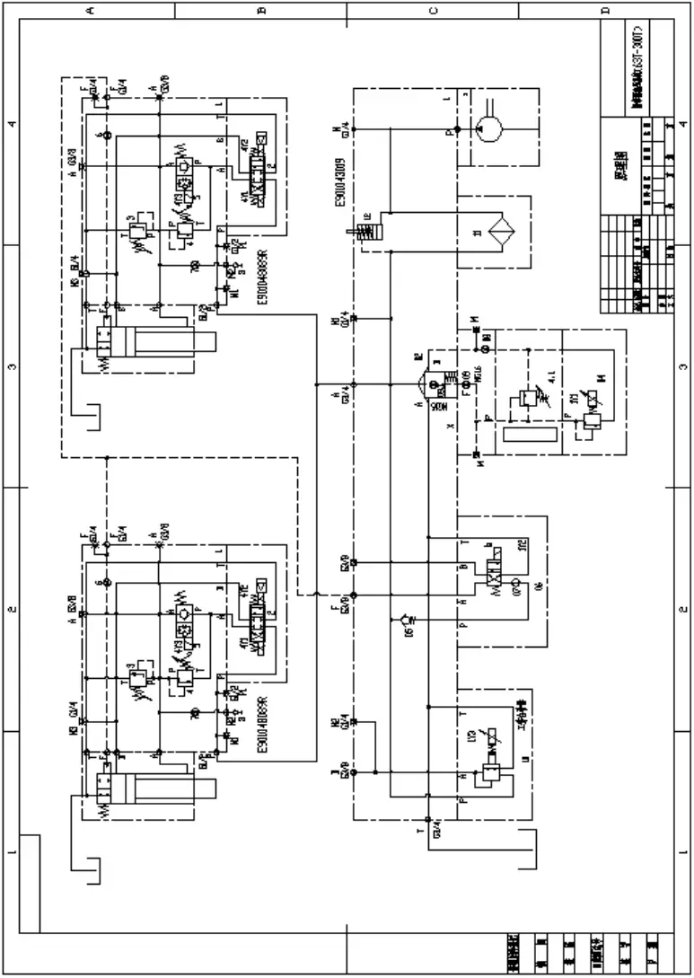
Appendix: Schematic Diagram Of Electro-Hydraulic Servo Press Brake Hydraulic System (400-1200 tons)
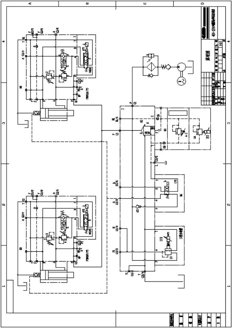
Appendix: Schematic Diagram Of Electro-Hydraulic Servo Press Brake Hydraulic System (400-1200 tons)
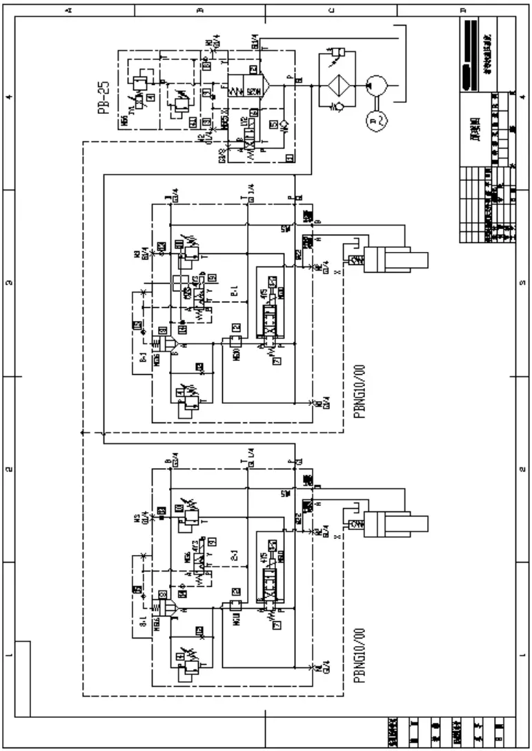
Appendix: Schematic Diagram Of Electro-Hydraulic Servo Press Brake Hydraulic System (1600-3000 tons)

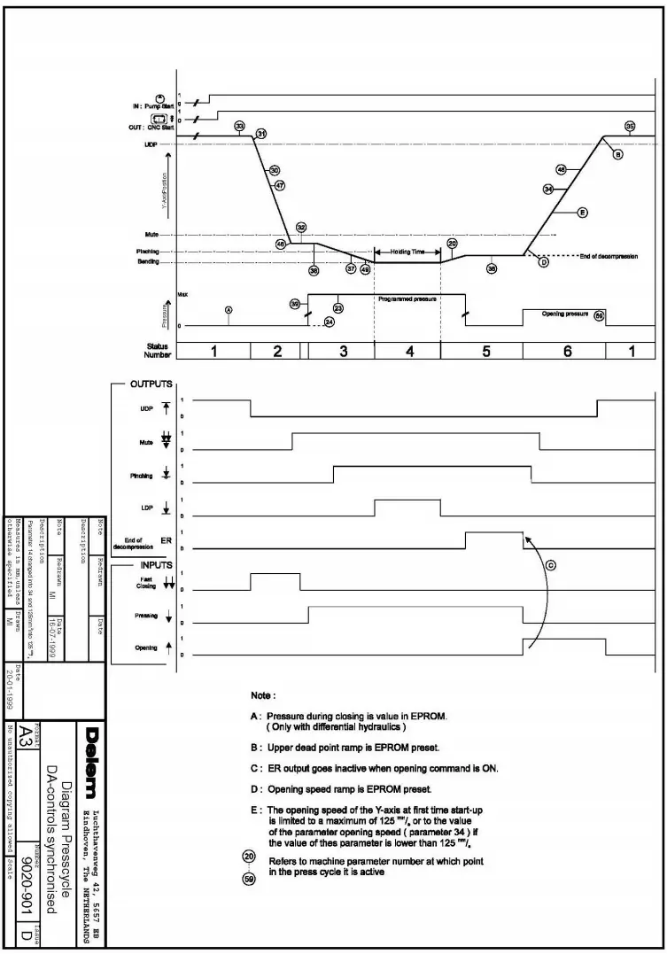
Appendix: Timing Chart Of Electro-Hydraulic Servo Press Brake

Appendix: Schematic Diagram Of Press Brake Action Sequence
Appendix: Principle Of Pump-Controlled Hydraulic System Of Electro-Hydraulic Servo Press Brake

Appendix: Schematic Diagram Of Hydraulic System For Torsion Bar Synchro Press Brake

As the founder of MachineMFG, I have dedicated over a decade of my career to the metalworking industry. My extensive experience has allowed me to become an expert in the fields of sheet metal fabrication, machining, mechanical engineering, and machine tools for metals. I am constantly thinking, reading, and writing about these subjects, constantly striving to stay at the forefront of my field. Let my knowledge and expertise be an asset to your business.