Have you ever wondered how manufacturers achieve precision and efficiency when cutting stainless steel? This article dives into six advanced techniques for stainless steel cutting, highlighting their benefits and applications. From gas flame and plasma methods to carbon arc gouging, each technique offers unique advantages in terms of precision, speed, and environmental impact. By reading this, you will gain insights into the most effective ways to handle this resilient material, enhancing your understanding of industrial metalworking processes.
Welded components made of stainless steel, such as containers and pipelines, undergo processes including plate and pipe blanking, sheet metal processing, and welding groove processing. In the manufacturing of storage containers, it is inevitable to create manholes and carry out forming processes on the end faces of the heads.
When welding on both sides, the reverse weld seam needs to be cleaned, and defects in the weld joint require rework and additional welding. These processing steps are indispensable in the production and manufacturing process. While most of the processing steps are carried out using mechanical methods such as shearing, planing, milling, and turning, they require a variety of types of machinery to complete.
In some cases, it is appropriate to use pneumatic chisels, but the high labor intensity, noise, and pollution in the work environment are detrimental to the health of the operators.
Using gas flame or plasma cutting methods to complete the aforementioned processes has many advantages in improving working conditions, increasing efficiency, and reducing environmental pollution, but the downside is that the precision of the cut surfaces after some processing may not be as good as that achieved through mechanical processing.
Let’s discuss several techniques for gas flame and plasma cutting of stainless steel.
I. Oxy-fuel Gas Cutting Technology
Gas cutting is a method that uses the thermal energy of a gas flame to preheat the cutting area of a workpiece to a certain temperature, then sprays a high-speed cutting oxygen flow to ignite the metal and release heat, thus achieving thermal cutting.
The reason why ordinary low carbon steel is easy to cut and produces good cutting quality is that the oxides generated from the combustion have a lower melting point than the steel itself. Simultaneously, the heat from the combustion raises the oxides to a molten state, which are then blown away by the gas flow.
When oxy-fuel gas flame cutting stainless steel, the main issue is the formation of high melting point chromium oxides on the cut surface, which prevents the metal from burning and creates difficulties for continuous cutting.
In order to smoothly cut stainless steel, besides having sufficiently pure oxygen at a certain pressure and a well-directed cutting oxygen flow (meaning a sufficiently long and powerful cylindrical cutting oxygen flow), some special process measures need to be taken.
Oxygen-Flux Gas Cutting Process
Oxygen-flux gas cutting refers to a process in which pure iron powder or other fluxes are added to the cutting oxygen flow to utilize their combustion heat and slag-making effects for gas cutting. The melted iron oxides and chromium oxides are mixed, making them diluted slag, improving the flowability of the slag.
In cases of significant heat increase, a mixed liquid slag is formed, which is then blown away by the cutting oxygen from the kerf. This process is also known as powder injection cutting and can be used to cut thicker stainless steel materials and stainless steel casting risers. There are two types of fluxes: commonly used and high-efficiency, with their composition components listed in Table 6-1.
Table 6-1: Fluxes for Cutting Stainless Steel
Type
Composition of Fluxes (mass fraction, %)
Note
Common Fluxes
Low carbon iron powder or low carbon iron powder with lead powder
The particle size for internal feeding is 0.5-1.0mm, while the particle size for external feeding is 0.1-0.3mm.
After thorough mixing of the above components, granules of 0.3-1.2mm are produced.
Equipment for oxy-flux cutting can be divided into two categories based on the method of flux delivery.
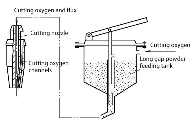
(1) Internal Powder Feed Oxy-Flux Cutting Process
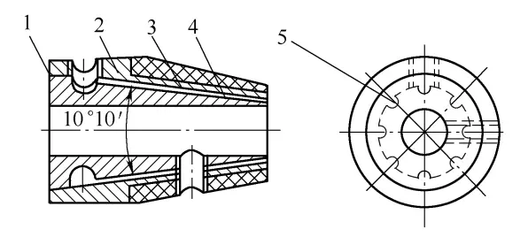
Its characteristic is to use cutting oxygen to deliver flux from the flux tank through the cutting nozzle components, as shown in Figure 6-1.
To prevent iron powder from oxidizing and burning inside the flux tank, coarse iron powder with a particle size of 0.5-1.0mm is commonly used. Due to its large particle size and fast ejection speed, it does not fully combust on the surface of the workpiece during cutting. Therefore, it is commonly used for cutting workpieces with a thickness of less than 500mm.
In order to increase cutting speed, a small amount of aluminum powder can be added to the iron powder. When using internal powder feed equipment, natural gas can be used as a fuel. The cutting process parameters for cutting 18-8 stainless steel sheets using internal powder feed nozzles are shown in Table 6-2.
Table 6-2: Process Parameters for Cutting 06Cr18Ni11Ti Stainless Steel Plate Using Internal Powder Feed Nozzle
Process Parameters
Thickness in millimeters
10
20
30
40
70
90
Nozzle Size
1
1
1
2
3
3
Oxygen Pressure/MPa
0. 40
0. 49
0. 54
0. 59
0. 69
0. 78
Oxygen Consumption/(m3/m)
1. 1
1. 3
1. 6
1. 75
2. 3
3. 0
Fuel Gas (Natural Gas) Consumption/(m3/m)
0. 11
0. 13
0. 15
0. 18
0. 23
0. 29
Flux Consumption/(kg/m)
0.7
0.8
0. 9
1. 0
2. 0
2. 5
Cutting Speed/(mm/min)
230
190
180
160
120
90
Kerf Width/mm
10
10
11
11
12
12
When using the inner powder feeding oxygen-fuel cutting method abroad, it is often equipped with a fast cutting nozzle with flowing water spray at the outer edge of the nozzle. The iron powder has a particle size of 0.5 to 1.0 mm, resulting in a relatively ideal flatness of the cut surface. Typically, the cut does not require mechanical processing to meet the dimensional requirements.
The flowing water spray around the workpiece reduces the warping of the steel plate during cutting, improves the corrosion resistance of the processed end face, and also reduces the airborne dust in the cutting environment, thereby improving working conditions.
This method can cut stainless steel plates up to 150 mm thick and can also cut layered (stacked) steel plates, such as 2-3 mm × 40 layers for ordinary carbon structural steel plates and 2 mm × 40 layers for stainless steel plates.
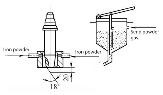
(2) External Powder Feeding Oxygen-Fuel Cutting Process
The characteristic of external powder feeding oxygen-fuel cutting is the use of low-pressure (0.04-0.06 MPa) air or nitrogen to independently introduce fine iron powder larger than 130 mesh into the flame heating zone outside the cutting nozzle, as shown in Figure 6-2.
Due to the small particle size of the iron powder and the low ejection speed, it can be rapidly heated to its ignition point and burn, releasing a large amount of heat, effectively breaking the oxide film on the surface of the workpiece. Since the powder is fed independently, it can overcome the damage to the oxygen channel caused by flushing.
Therefore, it is used for cutting stainless steel materials with a thickness exceeding 500 mm or for cutting the riser of stainless steel castings with a diameter of 1000-1300 mm.
The process parameters are as follows:
Flux: 100% iron powder, particle size of iron powder 0.1-1.3 mm; preheating oxygen pressure 0.8-1.0 MPa; cutting oxygen pressure 0.8 MPa, cutting oxygen consumption 200 m3/h; acetylene pressure >0.01 MPa, acetylene consumption 20 m3/h; the powder conveying gas is nitrogen, and the flux flow rate is 18 kg/h; cutting speed is 20-25 mm/min.
Figure 6-2 Schematic Diagram of Powder-Injected Oxygen Cutting Nozzle
Vibration Gas Cutting Process
Vibration gas cutting is a simple and practical method for cutting stainless steel using the vibration of an oxygen-fuel gas cutting torch.
The essence of the vibration gas cutting method is to vibrate the cutting torch during the cutting process to break through the refractory oxide film produced at the incision, thereby achieving the purpose of separating and cutting the metal.
The cutting process is illustrated in Figure 6-3. At the beginning of the cutting, the edge of the workpiece is preheated to a molten state, then the cutting oxygen flow is initiated, and the slag flows out from the incision. At this point, the cutting nozzle should be raised, and immediate back-and-forth as well as up-and-down vibrations should be applied.
The vibration has an amplitude of 10 to 15mm and a frequency of 60 to 80 times per minute. The vibration of the cutting oxygen flow breaks through the high-melting-point chromium oxide at the incision, allowing the iron to continue burning. With the help of the back-and-forth and up-and-down impact of the oxygen flow, the purpose of continued cutting is achieved.
A general oxyacetylene cutting torch, such as the G01-300 type, is used for the cutting torch. Compared with cutting carbon steel of the same thickness, the preheating flame needs to be larger and more concentrated, and the oxygen pressure needs to be increased by about 15% to 20%.
This type of vibration gas cutting is commonly used to cut off the risers of stainless steel castings with a diameter not exceeding 500mm, achieving the purpose of cutting, but the quality of the incision is very poor.
With the development of technology, oxygen-fuel gas flame cutting is rarely used for cutting stainless steel plates, and it is mostly used for cutting the risers of stainless steel castings.
Figure 6-3: Vibrational Gas Cutting of Stainless Steel
II. Carbon Arc Gouging Technique
Conventional Carbon Arc Gouging Technique
(1) Characteristics of Carbon Arc Gouging:
Carbon arc gouging utilizes a graphite or carbon rod as an electrode to generate an electric arc between the workpiece, melting the metal, and then uses compressed air to blow away the molten metal, thereby creating surface grooves.
During gouging, the electric arc reaches temperatures as high as 6000-7000°C, generating enough heat to melt the workpiece’s surface. The molten metal and slag produced are blown away by the compressed air (0.4-0.6 MPa) ejected from the carbon arc gouging nozzle. The continuous burning of the electric arc and the continuous blowing of compressed air remove the molten material, achieving the required grooving on the metal surface.
This gouging technique is primarily used for back gouging in double-sided welding, removing defects in weld seams, and can also be used for beveling in single-piece or irregular welds.
The processing capabilities of carbon arc gouging, compared to chipping or grinding wheel methods, possess the following characteristics:
1) Manual carbon arc gouging offers greater flexibility, allowing for operation in all positions.
2) When removing defects in weld seams or castings, the shape and depth of the defects can be clearly observed.
3) The noise during operation is lower than that of chipping, resulting in higher production efficiency.
4) In restricted or hard-to-reach areas, carbon arc gouging is more suitable for operation.
5) Carbon arc gouging produces smoke and dust, which can pollute the environment, and demands a higher level of operational skill.
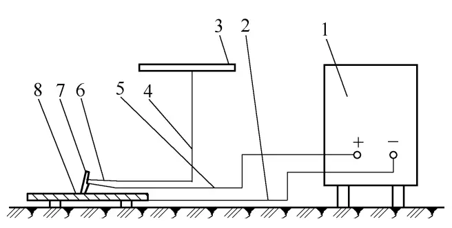
Equipment Used for Carbon Arc Air Gouging
The carbon arc air gouging comprises a power source, a compressed air supply, a gouging torch, carbon rods, cables, and hoses, as shown in Figure 6-4.
The power source utilizes a rectifier with a steep drop characteristic, and its rated current should be greater than the required current for carbon arc air gouging. For instance, when using a 7mm circular carbon rod, the cutting current required for carbon arc air gouging is 350A, and it is advisable to select a rectifier with a rated current of 500A.
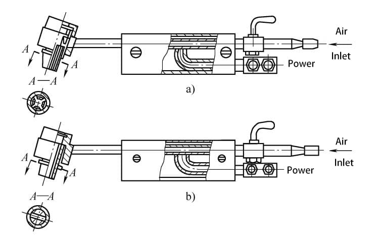
The gouging torch for carbon arc air gouging is primarily used to clamp the carbon rod and blow compressed air. Commonly used gouging torches are depicted in Figure 6-5, available in two forms: side-feed and circular-feed.
Carbon rods should possess characteristics of high-temperature resistance, good conductivity, and resistance to breakage. To enhance their conductivity and surface strength, a layer of pure copper is often plated on the surface of the carbon rods. Carbon rods are available in two forms: circular and flat (rectangular cross-section).
Circular carbon rods are mainly used for back-gouging weld seams, while flat carbon rods can be used for beveling, gouging weld beads, and cutting large amounts of metal.
Figure 6-4: Schematic Diagram of Carbon Arc Air Gouging
1—Arc Welding Rectifier 2—Grounding Cable 3—Compressed Air 4—Air Conduit 5—Welding Torch Cable 6—Gouging Torch 7—Carbon Rod 8—Workpiece
Figure 6-5 Schematic diagram of commonly used carbon arc air gouging guns
a) Side air gouging gun b) Circumferential air gouging gun
Air Gouging Process
In order to obtain high-quality gouging, correct process parameters must be ensured. The factors affecting the quality of air gouging are as follows:
1.Polarity of the Power Supply:
When gouging stainless steel with carbon arc, direct current reverse polarity connection (electrode connected to the positive pole of the power supply) is used. This results in stable arc during gouging, uniform gouging speed, continuous brushing sound of the arc, and consistent width on both sides of the gouge with a smooth and bright surface.
If direct current positive polarity connection (carbon rod connected to the negative pole of the power supply) is used, the arc will jitter, emitting intermittent sputtering sounds, and the sides of the gouge will exhibit an arc shape corresponding to the jitter during gouging. If this phenomenon occurs, the polarity should be reversed before re-gouging.
2.Gouging Current and Carbon Rod Diameter:
When gouging current increases, the gouge width, depth, and gouging speed also increase, resulting in a smoother gouge quality. However, if the gouging current is too high, the carbon rod will burn out quickly, or even melt, causing serious carbon infiltration and rough gouge surface.
If the gouging current is too low, the arc will be unstable, resulting in a small and shallow gouge, unstable gouging speed, low efficiency, and a tendency to cause slag adhesion. Table 6-3 introduces the parameters of commonly used carbon arc air gouging.
Table 6-3: Common Parameters for Carbon Arc Gouging
Carbon Electrode Cross-Section Shape
Specifications/ mm
Applicable Current/ A
Compressed Air Pressure/MPa
Carbon Electrode Extension Length/ mm
Angle between Carbon Electrode and Workpiece (°)
Circular
Φ3. 2
150 ~ 180
0.4~0.6
30 ~70
30 ~ 45
Φ3. 5
Φ4. 0
150 ~ 200
Φ5. 0
180 ~ 210
Φ6. 0
180 ~ 300
Φ7. 0
200 ~ 350
Φ8.0
250 ~ 400
Φ9. 0
350 ~ 500
Φ10. 0
400 ~ 550
Flat
3×8
200 ~ 250
0.4~0.6
30 ~70
30 ~ 45
4 ×6
4×8
200 ~ 300
4 ×12
300 ~ 350
5 ×10
300 ~ 400
5 ×15
400 ~ 500
The selection of carbon rod diameter is related to the thickness of the steel plate, as shown in Table 6-4. It is also related to the required groove width; the larger the carbon rod diameter, the wider the groove. Generally, the carbon rod diameter should be 2-4mm smaller than the required groove width.
Table 6-4: Selection of Carbon Rod Diameter
Steel Plate Thickness
4 ~6
6~8
8 ~ 12
>10
>18
Carbon Rod Diameter
4
5 ~6
6~7
7 ~ 10
10
3.Cutting Speed
It must be adapted to the gouging current and air pressure to ensure the normal process of gouging. Excessive speed or aggressive downward movement of the carbon rod can cause the carbon electrode head to come into contact with liquid metal or unmelted metal, leading to arc extinguishing due to short-circuiting.
Excessive speed can also cause the carbon electrode head to detach and stick to unmelted metal, resulting in carbon inclusion defects. In such cases, the arc should be re-established at the front of the defect, and a layer should be gently gouged off by hand to remove the defect before continuing gouging.
If the gouging speed is too slow, the arc will elongate, leading to unstable arcs or even arc extinguishing. Generally, a cutting speed of 0.8-1.2m/min is recommended.
4.Compressed Air Pressure
Compressed air pressure directly affects cutting speed and the surface quality of the groove. Higher pressure can increase cutting speed and the smoothness of the groove surface, while excessively low pressure can cause slag adhesion on the groove surface. Typically, compressed air pressure should be maintained at 0.4-0.6MPa.
The moisture and oil content in compressed air can be restricted by filters installed in the air pipes, and it is advisable to use new silicone gel as the filter medium.
5.Carbon Electrode Extension Length
An extension length of 30-70mm is optimal for the carbon electrode. An excessively long extension length increases resistance and leads to severe carbon rod burning, while a too-short length often results in short-circuiting due to the metal parts of the gouging gun coming into contact with the workpiece, causing arc instability.
During the gouging process, it is normal for the carbon rod to burn, and the extension length should be periodically adjusted. When the extension length is less than 25mm, it should be readjusted to 70-80mm.
6.Angle between Carbon Rod and Workpiece
The angle between the carbon rod and the workpiece primarily affects the groove depth and cutting speed. An increase in the angle leads to greater groove depth and reduced cutting speed, while a decrease in the angle results in shallower grooves and faster cutting speeds. Generally, a recommended angle for manual carbon arc gouging is 30°-45°.
7.Arc Length for Carbon Arc Gouging
During the gouging process, it is advisable to keep the arc length relatively short, around 2-3mm. An excessively short arc length can lead to carbon inclusion defects, while an excessively long arc length can cause the arc to be blown out by cold air, resulting in arc instability or even extinguishing.
An excessively long arc length can also lead to the compressed air not being concentrated enough, causing the melted metal to not be blown away in time, widening the heat-affected zone of the gouge and deteriorating the surface roughness of the groove. Additionally, during the gouging process, the carbon rod should not be swung; instead, it should be moved straight forward at a pre-selected angle to ensure uniform groove dimensions.
(4) The Influence of Carbon Arc Air Gouging on the Corrosion Resistance of Stainless Steel Welds
When carbon arc air gouging stainless steel, it can affect the surface of the gouged metal through carburization and thermal action, leading to the deterioration of the intergranular corrosion resistance of the stainless steel weld joints. Table 6-5 presents the analysis of carbon content when carbon arc air gouging 18-8 stainless steel.
From the table, it can be observed that the metal spatter-slag produced by carbon arc air gouging has a carbon content (w(C)) as high as 1.3%. However, the liquid metal carburization during the gouging process is quickly blown away by compressed air, resulting in a surface carbon content (w(C)) of only 0.075%. Therefore, the carburization effect of carbon arc air gouging on 18-8 stainless steel is extremely minimal.
According to actual measurements, the depth of the carburized layer on the metal surface after gouging generally ranges from 0.02 to 0.05mm, with the deepest point not exceeding 0.11mm, and the carburized layer consists of intermittent molten metal.
Although carbon arc air gouging has a heating effect on the gouged surface, the high-temperature liquid metal formed below the arc column is quickly blown away and no longer continues to heat the gouged surface. It can be said that the thermal influence zone of carbon arc air gouging is smaller than that of electrode arc welding, and under the correct operating specifications, the thermal influence zone is only about 1mm.
Therefore, it can be seen that the carburization and thermal effects of carbon arc air gouging on 18-8 stainless steel are very weak.
Table 6-5: Carbon Content Analysis of 18-8 Stainless Steel After Carbon Arc Air Gouging
Sampling Locations
Mass fraction of carbon (%)
Spattered metal from carbon arc air gouging
1. 3
Slag adhering to the edge of the groove
1. 2
Surface layer of the groove: 0.2~0.3mm
0. 075
Base metal
0. 05 ~ 0. 075
Water-Spraying Carbon Arc Air Gouging Process
As is well known, the smoke and dust generated during the carbon arc air gouging process seriously pollute the environment and affect the health of workers. This situation is particularly severe when carbon arc air gouging is conducted in enclosed containers, as operators are prone to feeling chest tightness and shortness of breath.
Due to the mobile nature of carbon arc air gouging operations, conventional exhaust and ventilation measures are insufficient in addressing the pollution issues within the operators’ work areas.
In order to control the smoke and dust pollution caused by carbon arc air gouging, the water-spraying carbon arc air gouging process has been adopted based on the principle that water mist can eliminate smoke and dust.
Characteristics of Water-Spraying Carbon Arc Air Gouging Process
The water-spraying carbon arc air gouging process involves equipping a standard carbon arc air gouging gun with a water spraying device. Compressed air is used to spray water around the carbon rod from the gun, creating a substantial and evenly dispersed water mist. The shielding effect of the water mist helps reduce the diffusion of smoke and dust.
Additionally, the cooling effect of the water mist decreases the heated and molten lengths of the carbon rod, thereby reducing its consumption. The water mist spray also prevents the molten metal from adhering easily to the edges of the workpiece groove, facilitating the removal of slag.
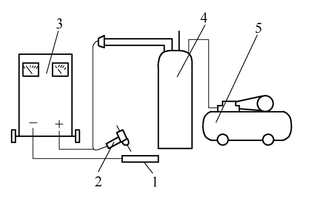
Equipment for Water-Spraying Carbon Arc Air Gouging
The equipment for water-spraying carbon arc air gouging consists of a power supply, water supply device, compressed air, and the carbon arc air gouging gun, as illustrated in Figure 6-6.
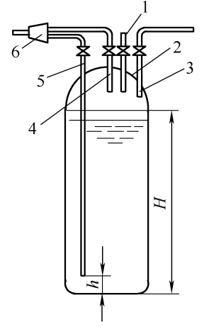
The water supply device, an essential component of the water-spraying carbon arc air gouging equipment, is depicted in Figure 6-7. In this diagram, compressed air is connected to the container via pipeline 1, while water is introduced into the container through the inlet pipe 3 until the water level reaches height H (lower than the bottom of the air outlet pipe 4), at which point the inlet valve is closed.
When the inlet valve for the compressed air pipeline 1 is opened, compressed air is supplied, and if the valve for the air outlet pipe 4 is opened, compressed air is released from the outlet pipe. If the valve for the water outlet pipe 5 is opened while the valve for the air outlet pipe 4 is closed, pressurized water is sprayed from the water outlet pipe.
By simultaneously opening the valves for the air outlet pipe 4 and the water outlet pipe 5, compressed air and pressurized water are mixed at the three-way joint 6 and sprayed out as a mist. Adjusting the opening of the valves for the air outlet pipe 4 and the water outlet pipe 5 can change the airflow and the size of the water mist. When the water level in the supply container is lower than h, no water mist is sprayed.
In this case, water can be added to the container through the inlet pipe 3 to resume operation. The key to water-spraying carbon arc air gouging lies in creating a well-designed water supply assembly to achieve a uniform and dispersed water mist.
Additionally, the three-way joint 6 for mixing compressed air and pressurized water should be positioned as close as possible to the air gouging gun (generally within 10m) to minimize pressure loss in the pipeline, ensuring that the gun sprays a sufficiently robust water mist.
A standard carbon arc air gouging gun can be easily modified for use as a water-spraying carbon arc air gouging gun with minor adjustments. As shown in Figure 6-8, the inner body 4 and the inner sleeve 2 of the circular air gouging gun are brazed together at the left end using copper, ensuring a sealed end.
Additionally, the inner diameter of the air passage hole 5 on the inner body 4 is enlarged from 1mm to 1.5mm, enabling its use for water-spraying purposes.
Figure 6-6 Schematic diagram of water arc air plow equipment
Figure 6-7 Schematic diagram of water supply device
1-Air intake pipe for compressed air 2-Container 3-Inlet pipe for water 4-Outlet pipe for compressed air 5-Outlet pipe for water 6-Water and air mixed three-way pipe joint
Figure 6-8 Water jet carbon arc air plow gun
1-Brazing point 2-Inner sleeve 3-Insulating outer sleeve 4-Inner body 5-Air passage orifice
(3) Process Parameters of Water Jet Carbon Arc Air Plow
The operating method and factors affecting the quality of air plowing in water jet carbon arc air plow are the same as those in carbon arc air plow. The process parameters for the 18-8 stainless steel plate in water jet carbon arc air plow are shown in Table 6-6, resulting in a good surface quality of the groove.
Table 6-6 Process Parameters for Water Jet Carbon Arc Air Plow of 18-8 Stainless Steel Plate
Carbon Rod Diameter (mm)
7
Water Spray Volume (mL/min)
65 ~ 80
Carbon Arc Air Plow Current (A)
400 ~ 500
Groove Depth (mm)
4~6
Air Pressure (MPa)
0. 45 ~ 0. 60
Groove Width (mm)
9 ~ 11
Note: The inclination angle of the carbon rod during initial plowing is 15° to 25°, while the normal cutting inclination angle is 25° to 45°.
The water jet carbon arc air plow for 18-8 stainless steel not only overcomes the environmental pollution hazards caused by carbon arc air plowing but also, due to the cooling effect of water, reduces the heat on the groove surface, preventing a decrease in corrosion resistance.
Measurements of the dust generated when using water jet carbon arc air plow and carbon arc air plow are presented in Table 6-7. From the measurement results in the table, it is evident that the water jet carbon arc air plowing method significantly reduces the dust content in the working environment. The advantages are even more pronounced when using the water jet carbon arc air plow method for air plowing within a sealed container.
Table 6-7: Dust Measurement Generated by Carbon Arc Air Gouging
Location of Measurements
Dust Measurement/ (mg/m³)
Reduction level of water jet carbon arc air gouging compared to carbon arc air gouging
Carbon Arc Air Gouging
Water jet carbon arc air gouging
1.0m directly in front and 0.5m above the test plate during gouging.
56.3
13.8
75. 5%
Helmet area behind the test plate during welding.
11.5
1.15
90%
III. Water Jet Melting Electrode Arc Cutting Technology
This cutting method, compared to oxy-fuel flame cutting, has the advantages of simple operation, low cost, and high production efficiency.
Cutting Principle
The water jet melting electrode arc cutting method relies on igniting the arc by contacting the cutting wire with the workpiece, melting the metal, and then rapidly removing it by high-pressure, high-speed water jet impact, forming the incision as the cutting torch moves.
Due to the effect of high-pressure water jet, the heat-affected zone of the incision is small, which is extremely beneficial for cutting 18-8 stainless steel plates, as it can reduce or prevent the occurrence of intergranular corrosion. Compared to carbon arc air gouging, it can also reduce air pollution in the work area and improve the operating environment.
Cutting Equipment
The water jet melting electrode cutting equipment can be modified from the original MZ-1000 (EA-1000) submerged arc welding machine.
After modification, the wire feeding speed is 740-2000mm/min, the traveling speed is 73-1600mm/min, and the power characteristic of the welding machine is changed from a drooping characteristic to a flat characteristic. In addition, a 40W-40 vortex water pump (5.4m3/h, 1.73kW, head is 40m) is required, and water pressure is controlled by drainage.
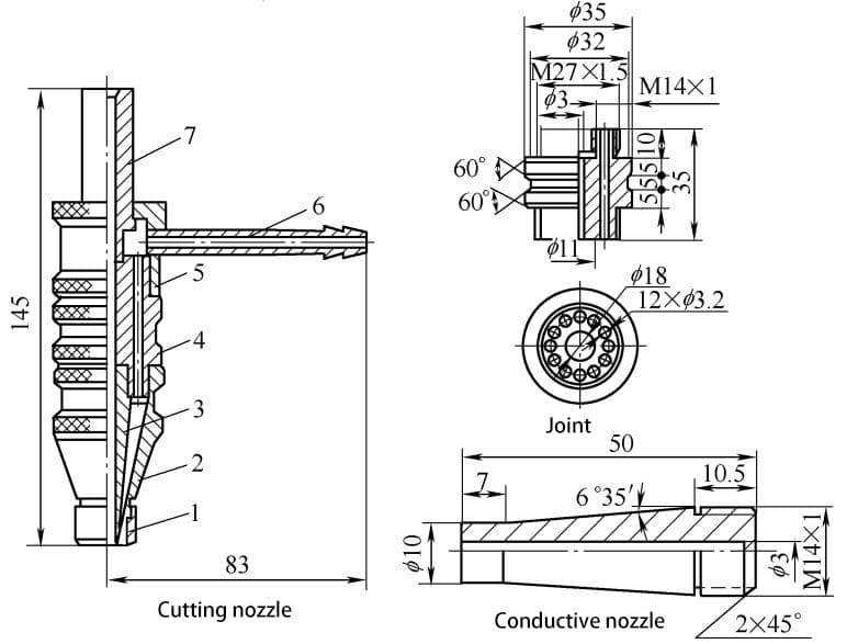
There are certain requirements for the cutting nozzle; the water jet should be concentrated and columnar, with sufficient impact force. The water jet and the cutting wire should be kept coaxial and perpendicular to the surface of the workpiece. The structural dimensions of the cutting nozzle are shown in Figure 6-9.
The sealing of the conductive nozzle 3 during cutting is critical, and failures often occur due to inadequate sealing.
When cutting stainless steel plates, a direct current power source should be used with reverse polarity connection. The no-load voltage should be 60-70V, and the arc voltage should be 40-60V. The gap between the nozzle and the workpiece should be 10-15mm. Ordinary iron wire with a diameter of 2.6mm should be selected as the cutting wire. Other process parameters can be found in Table 6-8.
The thickness of the stainless steel to be cut should not exceed 30mm. Single-layer steel plate cutting can be performed, or two or three layers of steel plates can be stacked and cut together.
Table 6-8 Parameters for Waterjet Melt Electrode Arc Cutting
Plate Thickness (mm)
Cutting Current (A)
Cutting Speed (mm/min)
Wire Feed Speed (m/min)
Water Pressure (MPa)
30
750
340
8~12
1.5
17
600
420
8~12
1.5
10
800
450
8~12
1.5
6
650-700
165
1.8
0.6
6 (two layers)
500-700
73
1.89
0.45
5 (two layers)
800
139
1.78
0.5
4 (three layers)
900
381
1.83
0.5
When using this method for cutting, to avoid concentrated slag accumulation on one side of the bottom, it is important to adjust the coaxiality of the cutting wire and the water jet as much as possible before cutting, and ensure the perpendicularity of the cutting wire to the workpiece.
When cutting circular workpieces, attention should be paid to maintaining good insulation between the carriage of the nozzle and wire feeding mechanism and the workpiece to ensure that the current only passes through the shortest path, thus avoiding multi-point conduction of the cutting wire, which could affect cutting stability and quality.
When cutting stainless steel plates, selecting appropriate cutting parameters and employing the correct operating methods can result in narrow, smooth incisions with no obvious heat-affected zone. Rapid cooling by high-pressure water jet results in minimal and neat metal burning at the incision edge, and reduces slag accumulation at the bottom of the incision.
The waterjet melt electrode arc cutting method has been widely adopted as a means of blanking 18-8 stainless steel plates.
IV. Plasma Arc Cutting Technology
Plasma arc cutting is a method of cutting metal materials using the thermal energy of a plasma arc. The plasma arc is a compressed electric arc formed inside the cutting torch through three compression effects—mechanical compression, thermal shrinkage, and magnetic shrinkage.
This compresses the cross-section of the arc column inside the nozzle, resulting in characteristics such as concentrated energy, high temperature, and controllable flame velocity.
The airflow speed in the plasma arc column is extremely high, and the core temperature reaches 15000-30000℃, far exceeding the melting points of all metals and non-metals. Utilizing this heat source, it can be used to cut high-temperature resistant, good thermal conductivity, and easily oxidized metals as well as non-metals.
In production, it is widely used to cut stainless steel, copper, aluminum, and their alloys. The plasma arc cutting process does not rely on oxidation reactions to cut metals; instead, it relies on the heat of the electric arc itself to melt the metal being cut, while removing slag through high-speed airflow.
Its applicability is broader than oxy-fuel flame cutting, as it can be used for various materials, cutting out workpieces of different diameters and various curved parts with the aid of contouring and numerical control devices. It also features fast cutting speed and minimal deformation at the cut.
The General Plasma Arc Cutting Process
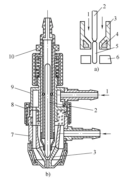
Depending on the form of compressed electric arc, plasma arcs can be classified into transferred and non-transferred arcs. Typically, a transferred plasma arc cutting machine is used to cut metal materials. The cutting principle and a typical cutting torch are illustrated in Figure 6-10.
The components of the equipment
The plasma arc cutting machine is divided into manual and mechanical types. Its equipment consists of a power supply, cutting torch, control system, gas system, and water cooling system.
The mechanical cutting machine is equipped with a speed-adjustable cutting carriage. Currently, manual cutting machines such as the LG-400 model can be used for manual cutting of straight lines and various geometric shapes, with a maximum stainless steel cutting thickness of 40mm.
The mechanical plasma arc cutting machine, such as the LG3-400 model, can automatically cut straight lines and circles. It can also cut any shape of workpiece through profile cutting and numerical control devices, with a maximum stainless steel cutting thickness of 40-60mm.
The cutting diameter of the circle ranges from 200mm to 1000mm. The technical parameters of several domestically produced plasma arc cutting machines are listed in Table 6-9.
Figure 6-10: General principle and cutting torch of plasma arc cutting
a) Cutting principle b) Typical cutting torch 1—Gas 2—Electrode 3—Nozzle 4—Cooling water 5—Arc 6—Workpiece 7—Lower torch body 8—Insulating nut 9—Upper torch body 10—Adjusting nut
Table 6-9: Technical parameters of several plasma arc cutting machines
Product Models
Voltage/V
No-load Voltage/V
Operating Voltage/V
Rated Cutting Current/A
Current Adjustment Range/A
LG—100
380
150
100 ~ 150
100
10 ~ 100
LG400
220
180 ~ 270
70 ~ 120
400
120 ~ 400
LG3400
220 or 380
180 ~ 270
80 ~ 180
400
125 ~ 400
LG500
380
400
100 ~ 250
500
100 ~ 500
Product Models
Load Continuity Rate (%)
Electrode Diameter (mm)
Cutting Speed (m/h)
Cutting Thickness (mm)
LG—100
60
2.5
6-170
2.5-25
LG400
60
5.5
Manual
40
LG3400
60
5.5
3-150
40-60
LG500
60
6.0
15
100-150
The plasma arc cutting torch is similar to the plasma arc welding torch. It generally consists of an electrode, electrode holder, nozzle, cooling water jacket, middle insulator, and gas and water pipes. The working gas can be introduced axially or tangentially, or a combination of both. The most commonly used method is tangential blowing, which provides the best compression effect for the plasma arc.
The electrode in the cutting torch must be coaxial with the nozzle, and the nozzle must simultaneously pass through working gas and cutting gas, so the quality requirements for the nozzle are high. This relates to cutting capability, cut quality, and the lifespan of the nozzle.
In the past, thoriated tungsten rods (grade WT-15 or WT-20) were commonly used as electrode materials, but due to the health impact of radioactive elements, their use has been discontinued. It is recommended to use ceriated tungsten rods (WCe-20 to WCe-40) and rhenium tungsten rods (W-1Re or W-3Re) instead. The choice of electrode diameter is related to the maximum allowable current, as shown in Table 6-10.
Table 6-10: Permissible Current for Different Diameter Electrodes
Electrode Diameter (mm)
4
5
6
Maximum Permissible Current (A)
250
360
550
Selection of Process Parameters
Gas Selection
Currently, commonly used gases for plasma arc cutting include nitrogen, hydrogen, argon, and their mixtures, as shown in Table 6-11. Among these, nitrogen is the most cost-effective, poses minimal hazards during use, and enjoys the widest application. It is important to choose nitrogen gas that complies with the national standard (GB/T3864-2008) to avoid nozzle and electrode damage.
The cutting gas acts as a thermal insulator and insulator between the arc column and the nozzle wall, compressing the arc to ensure stable combustion. Simultaneously, it serves as an ionizing medium and a conductor of arc heat, rapidly melting the workpiece after heating.
Additionally, the introduced gas also serves to cool the electrode. Under similar process conditions and comparable process parameters, the influence of nitrogen gas flow on cutting quality can be seen in Table 6-12.
Table 6-11: Commonly Used Gases for Plasma Arc Cutting
Workpiece Thickness (mm)
Types of Gases
Open circuit voltage (V)
Cutting voltage (V)
≤120
N2
250 to 350
150 to 200
≤150
N2 + Ar (φN2 60% ~ 80%)
200 to 300
120 to 200
≤200
N2 + H2 (φN2 50% ~ 80%)
300 to 500
180 to 300
≤200
Ar + H2 (φH2 0 ~ 35%)
250 to 500
150 to 300
Table 6-12: Effect of Nitrogen Flow Rate on Cutting Quality
Cutting Current (A)
Cutting Voltage (V)
Gas Flow Rate (L/h)
Kerf Width (mm)
Kerf Surface Quality
240
84
2050
12.5
Excessive dross
225
88
2200
8.5
Some dross
225
88
2600
8
Light dross
230
88
2700
6.5
No dross
235
82
3300
10
Some dross
230
84
3500
Not fully cut
Process Parameters
When using plasma arc cutting for stainless steel, it’s crucial to select appropriate process parameters to ensure a smooth metal surface, minimal dross, and narrow kerf width.
The relevant process parameters for cutting stainless steel plates can be found in Table 6-13. Improper parameter selection not only jeopardizes the cutting quality but also leads to dual arcing during the cutting process, and in severe cases, it can result in interrupted cutting and significant damage to the nozzle and electrode.
Table 6-13: Process Parameters for Plasma Arc Cutting of Stainless Steel
Steel Plate Thickness (mm)
Nozzle Diameter (mm)
Cutting Voltage (V)
Cutting Current (A)
Nitrogen Flow Rate (L/h)
Cutting Speed (m/h)
Cutting Width (mm)
8
3
120
185
2100 to 2300
40 ~ 50
4.2
12
120 to 130
200 to 210
2300 to 2400
40
4.2 ~ 5.0
16
120 to 130
210 to 220
2400 to 2600
40
4.5 ~ 5.5
20
120 to 130
230 to 240
2500 to 2700
32 ~ 40
4.5 ~ 5.5
25
125 to 135
260 to 280
2500 to 2700
45 ~ 55
5 ~ 6
30
135 to 140
280 to 300
2500 to 2700
35 ~ 40
5.5 ~ 6.5
40
3.5
140 to 145
320 to 340
2500 to 2700
35
6.5 ~ 8.0
45
3.5
145
320 to 340
2400 to 2600
20 ~ 25
6.5 ~ 8.0
100
4.5
145
380
2500
—
—
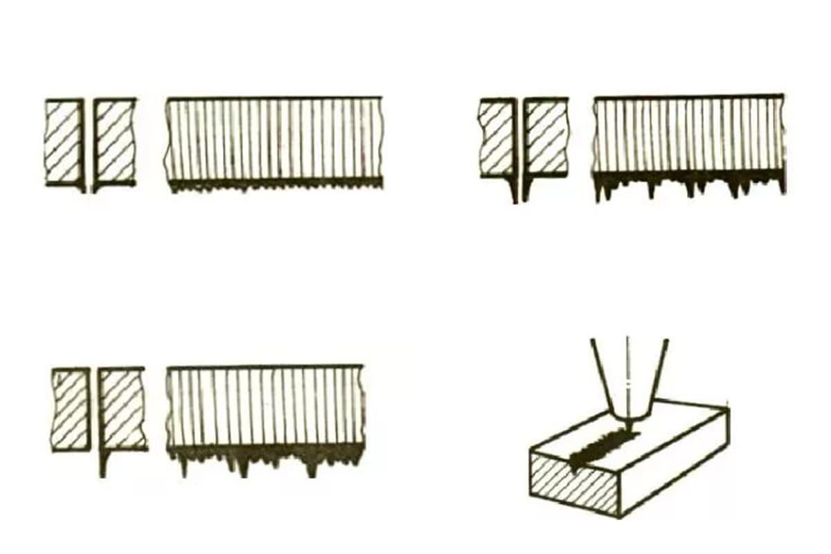
Cutting speed is a crucial factor affecting the quality of the cut. Keeping the power constant, increasing the cutting speed can result in a smaller heat-affected zone, narrower kerf, and reduced thermal impact area. However, excessively high cutting speed may not penetrate the workpiece.
If the cutting speed is too slow, it not only reduces production efficiency but also leads to rough surface and slag hanging. The impact of cutting speed on cutting quality is illustrated in Table 6-14.
Table 6-14: The Impact of Cutting Speed on Cutting Quality
Cutting Current (A)
Cutting Voltage (V)
Cutting Speed (m/h)
Kerf Width (mm)
Kerf Surface Quality
160
110
60
5
Slight slag
150
115
80
4.0 ~ 5.0
Slag-free
160
110
104
3.4 ~ 4.0
Smooth and slag-free
160
110
110
Slaggy
160
110
115
Unable to cut through
Operating Techniques
Before cutting, the starting point should be thoroughly cleaned to maintain good electrical conductivity. For thick workpieces, it’s best to preheat the starting point with a small arc before cutting.
Cutting should commence from the edge of the workpiece, and the cutting torch should be moved after the edge is pierced. If cutting from the edge of the plate is not permissible, a small hole with a diameter of approximately 1-5mm should be drilled at the starting point of the steel plate to prevent splashing of slag due to the strong blowing force of the plasma arc, which would otherwise make the operation difficult.
The distance from the tip of the electrode to the end face of the nozzle should be controlled within 10-15mm. An appropriate distance allows the arc to be well compressed within the nozzle, concentrating energy and thereby increasing the temperature of the plasma arc and enhancing cutting capability.
The distance from the nozzle to the workpiece should not exceed 10mm. A distance that is too large will affect the effective utilization of arc power, reducing cutting capability, while a distance that is too small will make it difficult for the operator to control.
Throughout the entire cutting process, the cutting torch should be kept perpendicular to the surface of the workpiece to prevent skewed and unsmooth cuts, as well as the formation of dross on the bottom surface of the cut.
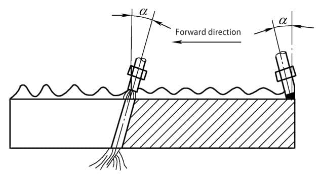
To improve cutting quality and increase production efficiency, the cutting torch can typically be tilted at an angle (0-45 degrees) in the plane where the cut is located, in the opposite direction of the cutting. When cutting thin plates, a larger backward tilt angle should be used, whereas when cutting thick plates, a smaller backward tilt angle is more appropriate.
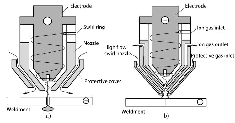
Water-Compressed Air Plasma Arc Cutting Process
Characteristics of Water-Compressed Air Plasma Arc Cutting
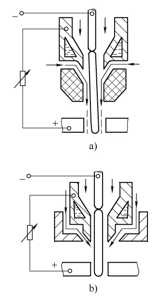
The principle of water-compressed air plasma arc cutting is illustrated in Figure 6-11. In addition to spraying working gas from the cutting torch, it is accompanied by a high-speed flowing water jet to rapidly expel the molten metal.
Figure 6-11 Water Recompression Air Plasma Arc Cutting Principle
a) Radial Water Inlet Cutting Principle b) Axial Water Inlet Cutting Principle
The high-pressure and high-speed water flow in the cutting torch serves to cool the nozzle on one hand and to recompress the arc on the other, forming a highly compressed plasma arc column with high energy density, which directly rushes toward the workpiece to be cut.
The water sprayed onto both sides of the cut prevents excessive melting, reduces the heat-affected zone due to the vertical cut, and part of the water injected into the cut is decomposed by the high temperature of the plasma arc into hydrogen and oxygen, which, together with the working gas, form the cutting gas, giving the plasma arc higher energy.
The unevaporated and undecomposed water has a strong cooling effect on the arc, concentrating the energy of the plasma arc and thus increasing the cutting speed.
Requirements for the Cutting Torch
There are two ways for high-speed water flow to enter the nozzle: one is radial entry of high-pressure water flow into the nozzle orifice and then spraying out from the center of the cutting nozzle, while the other is axial entry, entering from the peripheral annular water passage of the nozzle and then spraying out from the cutting torch.
The axial entry water-type cutting torch is shown in Figure 6-12. The electrode uses a 6mm diameter cerium tungsten electrode, ground to the same angle as the inner nozzle (30°), and welded to the electrode nozzle using silver-based brazing material, then welded to the cooling sleeve.
Figure 6-12 Schematic Diagram of the Structure of Water Recompression Air Plasma Arc Cutting Gun with Axial Water Inlet
1- External Nozzle 2- Internal Nozzle 3- Lower Collet Nut 4- Electrode Nozzle 5- Water Shield 6- Seal Ring 7- Seal Ring 8- Seal Ring 9- Cooling Jacket 10- Lower Gun Body Water Jacket 11- Internal Cooling Water Pipe 12- Inlet Pipe 13- Insulation Sheath 14- Upper Collet Nut 15- Upper Gun Body 16- Centering Screw 17- Center Sleeve 18- Fixed Nut 19- Adjustment Nut 20- Water Outlet Nozzle 21- Inlet Pipe 22- Inlet Air Pipe 23- Outlet Pipe 24- Omni-directional Air Inlet Hole 25- Electrode 26- Seal Ring 27- Recompression Water Pipe
These welds should not have any leakage. Cooling water flows in from the cold water pipe and flows out from the gap between the inner cooling water pipe and the cooling sleeve. With this cooling method, as long as there is enough cooling water, the electrode surface remains bright and shiny after several hours of operation, with very little evidence of burning.
The water-compressed air plasma cutting torch adds an external nozzle, effectively lengthening the plasma arc compression channel and enhancing the compression effect on the arc. During the cutting process, the external nozzle is close to the metal being cut, which may cause metal spatter and lead to a double arc.
To prevent this, an insulating layer of Al2O3, approximately 0.2mm thick, is sprayed on the outer surface of the pure copper nozzle, or ideally, a ceramic material is used for the external nozzle.
Cutting Process
A rectified plasma arc cutting power source can be used, with a no-load voltage of 400V or higher, up to 600V, depending on the cutting conditions. When cutting stainless steel using a power source with an operating voltage of 100-250V and an operating current of 100-150A, slagging can be completely eliminated, the upper edge of the cut is sharp, forming a narrow cut with verticality meeting requirements.
For cutting 8mm thick 18-8 stainless steel plate, the cut width is 4mm, with no discoloration on the cut surface and a bright, original metal luster.
When using water-compressed air plasma arc cutting, the nitrogen flow rate should be slightly lower than that used for regular plasma arc cutting.
Under certain power conditions, increasing the compressed water flow causes the cut to become visibly brighter and straighter, but there is also an optimal water flow rate.
When the water flow is too high, excessive arc compression leads to excessive heat dissipation, causing the arc to become unstable and shorter, increasing slagging, and even preventing cutting. Generally, the compressed water usage is 0.5-1.5L/min, which can be supplied by tap water.
Cutting current and voltage have a significant impact on cutting quality: as the cutting power of the plasma arc increases, the cutting speed and thickness also increase. It has been proven that, under the premise of being able to cut through, using high input power for high-speed cutting results in a higher quality cut compared to using low input power for slow cutting.
When increasing the cutting thickness, if only the cutting current is increased, the arc column becomes thicker and is prone to damaging the nozzle. If, while increasing the cutting current, the gas and compressed water flow are also increased, the arc voltage is also changed significantly, leading to an obvious increase in cutting ability and maintaining good cutting quality.
At the beginning of cutting, the distance between the nozzle and the surface of the workpiece should generally not be less than 6mm, but it is difficult to initiate the arc when it exceeds 10mm. During the cutting process, the distance between the nozzle and the surface of the workpiece can vary, with a maximum distance of up to 20mm. At this point, the arc remains stable and the quality of the cut remains consistent.
Typical parameters for cutting various metals using water-compressed air plasma arc cutting are shown in Table 6-15.
Table 6-15 Typical Cutting Parameters for Water Recompression Air Plasma Arc Cutting of Various Metals
Materials
Plate Thickness (mm)
Open Circuit Voltage (V)
Operating Voltage (V)
Cutting Current (A)
Gas Flow Rate (L/h)
Compressed Water Flow Rate (L/min)
Cutting speed (m/h)
Nozzle diameter (mm)
Kerf width (mm)
Internal
External
Aluminum Alloy
17
480
180
260
1800
0.75
54
4
6
3. 5
Aluminum Alloy
26
470
180
260
1800
1
45
4
6
4. 0
Aluminum Alloy
38
490
190
290
2100
0.75
30
4
6
5. 0
Aluminum Alloy
80
490
200
390
1350
1
15
4.3
6
10. 0
Stainless Steel
14
480
170
200
1650
1.25
54
4
6
4
Stainless Steel
18
480
180
300
1650
1.25
54
4
6
4
Pure Copper
15
490
200
300
1350
1
54
4
6
4. 0
Tool Steel
40
490
200
290
2100
0.75
30
4
6
5. 0
Note: 1.The data in the “Open Circuit Voltage” column is the reading indicated by the voltage meter, including the effect of the capacitance on the voltage in the circuit protection system. 2.The distance from the nozzle to the workpiece and the electrode diameter are both 6mm. 3.High-quality cut is required.
Evaluation
Analysis of Cut Quality
Upon inspecting the cut surface of the 18-8 stainless steel plate, the measured width of the heat-affected zone is only 0.02mm. This narrowing of the heat-affected zone is attributed to the cooling effect of water and the increased cutting speed. The cut can be directly welded, and the weld joint can undergo corrosion resistance inspection, showing no tendency for intergranular corrosion.
The water cooling of the workpiece results in a smooth cut, minimal post-cut thermal deformation of the workpiece, and a narrower kerf width compared to conventional plasma arc cutting.
Environmental Protection Analysis
Conventional plasma arc cutting generates a large amount of metal vapor, dust, and harmful gases, which, when inhaled, can impact the operator’s health. Even with the use of exhaust dust removal devices, it is not possible to completely eradicate environmental pollution and the significant noise during the cutting process. The use of a water purification workbench, as shown in Figure 6-13, can address this issue.
During cutting, the workpiece is placed on the water purification workbench’s water tank, with water added to the tank. The water surface is approximately 20mm away from the workpiece, until it comes into contact with the workpiece. In water-assisted compressed air plasma arc cutting, water sprayed from the nozzle forms a conical water curtain surrounding the plasma arc.
The high-speed gas emitted from the cutting torch, along with the oxide particles generated during the cutting process, enters the atmosphere along with the water, all of which settles at the bottom of the tank and does not disperse into the surrounding air.
For instance, when cutting a 38mm thick 18-8 stainless steel plate, using conventional plasma arc cutting, cutting a 25mm length results in 10g of fine dust; whereas with water-assisted compressed air plasma arc cutting equipped with a water purification workbench, the fine particle dust produced for the same length is only 0.11g.
The water and gas mixture also helps reduce harmful nitrogen dioxide. When using water-assisted compressed air plasma arc cutting machines and water purification workbenches, positioning the water optimally can reduce the emission of nitrogen dioxide into the surrounding air by 80%, while also reducing the noise during plasma arc cutting.
If the workpiece is cut approximately 200mm underwater, the characteristics of water can reduce the cutting noise by around 15dB, and can absorb the intense arc light, metal particles, dust, smoke, and ultraviolet rays generated during the cutting process, significantly improving the cleanliness of the work environment and benefiting the health of the operators.
Of course, in this scenario, as the cutting line cannot be seen, only mechanical cutting can be used, which is also the direction in which plasma arc cutting is evolving.
Figure 6-13: Water Purification Workbench
Air Plasma Arc Cutting Process
Air plasma arc cutting exists in two forms: single air and compound. The cutting principles and cutting torch are illustrated in Figure 6-14.
Figure 6-14 Air Plasma Cutting Principles and Torch
a) Single Air Cutting Principle b) Compound Cutting Principle c) Typical Single Air Cutting Torch
1 – Electrode Cooling Water 2 – Electrode 3 – Compressed Air 4 – Embedded Compressed Nozzle 5 – Compressed Nozzle Cooling Water 6 – Arc 7 – Workpiece 8 – Working Gas 9 – External Nozzle
Single Air Plasma Arc Cutting Process
This method utilizes compressed air from an air compressor as the working gas for plasma arc cutting. This form of air plasma arc cutting is cost-effective and the gas source is readily available. Compressed air is heated and ionized in the arc, and the oxygen generated undergoes a chemical exothermic reaction with the cutting metal, accelerating the cutting speed.
The high enthalpy of fully ionized air plasma results in a large arc energy. Compared to general plasma arc cutting, its cutting speed is faster, making it particularly suitable for cutting stainless steel, carbon steel, aluminum, and other materials with a thickness of 30mm or less.
Technical parameters of several domestically produced air plasma arc cutting machines are provided in the following.
Table 6-16 Technical Parameters of Several Domestically Produced Air Plasma Arc Cutting Machines
Product Models
Voltage / V
No-load voltage / V
Operating voltage / V
Rated cutting current / A
Current control range / A
Duty cycle (%)
Electrode diameter / mm
Cutting thickness / mm
LGK8-25
380
250
120
25
—
40
—
1~8
LGK8-40
380
240
110
40
20 ~ 40
40
3.5
10
LGK8-60
380
230
120
60
40 ~ 60
60
5
25
LGK8-100
380
220
110
100
50 ~ 100
60
10
30
LGK8-150
380
Mechanical 420
150
150
Tap-style
60
30
Manual 240
The electrode in this cutting method is subject to severe oxidation and corrosion, leading to significant electrode wear, so conventional pure tungsten electrodes or thoriated tungsten electrodes cannot be used. Generally, pure zirconium or pure hafnium electrodes embedded in a copper base are used. Even when using pure zirconium or pure hafnium electrodes, their service life is typically only 5 to 10 hours before needing replacement.
Table 6-17 lists the process parameters for air plasma arc cutting of stainless steel plates.
Table 6-17 Process Parameters for Air Plasma Arc Cutting of Stainless Steel Plates
Workpiece thickness / mm
Nozzle aperture / mm
No-load voltage / V
Operating voltage / V
Cutting current / A
Compressed air flow rate / (L/min)
Cutting speed / (cm/min)
8
1
210
120
30
8
20
6
1
210
120
30
8
38
5
1
210
120
30
8
43
In addition to cutting stainless steel plates, air plasma arc can also be used for root cleaning of stainless steel welds. Plasma arc root cleaning utilizes high-energy plasma to melt the metal, and then the molten metal is blown away by ionized gas, aiming to create a relatively smooth root surface without carburization, eliminating the need for grinding and allowing for direct welding.
A certain company conducted experiments on 04Cr13Ni5Mo martensitic stainless steel plates, with sample dimensions of 200mm×80mm×40mm. They used both air plasma arc and mechanical methods to create V-groove bevels, and then welded using the same welding materials and parameters, followed by conducting butt joint crack tests.
The test results indicated that a small amount of cross-sectional cracks appeared in the bevels processed by both methods at room temperature; however, no cracks appeared when the samples were preheated to 50°C and then welded. This implies that using air plasma arc to prepare bevels has no adverse effects on the welded joints. The plasma arc used for cutting is characterized by highly concentrated energy, short arcs, and a hard arc.
When used for root cleaning, the arc leaves deep and narrow grooves along its path, making it difficult to achieve a smooth surface due to the hardness of the arc. If the plasma arc is too soft, it can adversely affect the compression effect of the nozzle.
Because of the poor flowability and thermal conductivity of stainless steel molten metal, the bottom of the cut tends to overheat, and the remaining unblown molten metal in the cut fuses with the lower part of the cut, forming difficult-to-remove weld beads after solidification.
To address these issues, the company’s technical personnel developed a suitable nozzle after numerous trials and discussions, allowing for a moderate softness and hardness of the plasma arc, maintaining a sufficient arc length, and facilitating root cleaning. As a result, the plasma arc achieves both high root cleaning efficiency and high arc stability, while also producing a relatively smooth cutting surface without weld beads and with easy slag removal.
Compound Air Plasma Arc Cutting Process
The principle of the compound air plasma arc cutting process involves using a dual-layer nozzle, with the inner nozzle supplying the usual working gas and the outer nozzle supplying compressed air.
The advantages of this cutting method are twofold: on one hand, it utilizes compressed air for exothermic reactions in the cutting area to increase cutting speed; on the other hand, it avoids direct contact between air and the electrode, reducing electrode wear, and allowing for the use of pure tungsten or ceriated tungsten (tungsten-rhenium) electrodes.
Comparison of the Cutting Characteristics of Different Gases Used in Plasma Arc Cutting
Plasma arc cutting uses working gases such as nitrogen, hydrogen, argon, oxygen, and air. A comparison of their cutting characteristics is shown in Table 6-18.
Table 6-18: Comparison of the Cutting Characteristics of Different Gases Used in Plasma Arc Cutting
Cutting Method
Argon-Hydrogen Plasma Arc
Nitrogen Plasma Arc
Air Plasma Arc
Oxygen Plasma Arc
Plasma arc with compressed air and water
Cutting Characteristics
Excellent cutting performance; smooth, metallic luster on the cut surface; less smoke and dust compared to nitrogen plasma arc cutting; narrower kerf.
Disadvantages: prone to slag sticking; cutting speed is 20% to 30% slower than nitrogen plasma arc cutting; not very suitable for cutting sheet metal below 10mm in thickness.
Good cutting performance; good cut surface; less prone to slag sticking; easy to set cutting process parameters; cheaper gas compared to argon and hydrogen plasma arc cutting; low operating costs.
Disadvantages: generates more smoke and NOx; the cut surface has a nitride layer, which can lead to porosity during welding. Electrode wear is faster compared to argon and hydrogen plasma arc cutting.
Reasonable cutting performance; good cut surface; relatively fast cutting speed; easily obtain slag-free cut surfaces; easily accessible working gas; low operating costs.
Disadvantages: the cut surface contains nitrides; has limitations on the thickness of the material being cut; electrodes and nozzles are prone to wear and tear.
Reasonable cutting performance; good cut surface; fast cutting speed; easily obtain slag-free cut surfaces.
Disadvantages: has limitations on the thickness of the material being cut; electrodes and nozzles wear out quickly.
The cutting performance is excellent; the cutting speed is about 30% faster than typical nitrogen plasma arc cutting. The cut surface is smooth and bright, capable of achieving a vertical cut surface (only on one side of the cut), with a sharp upper edge and no slag on the lower edge. It experiences minimal thermal deformation and can suppress harmful effects such as light, toxic gases, and smoke. It has a strong cutting ability, particularly advantageous for cutting thick plates.
Disadvantages:having a nitride layer on the cut surface, making it difficult to see the cutting condition. Additionally, it requires a cutting platform with a water trough, and it demands a higher arc power.
Development of Plasma Arc Cutting
Underwater Plasma Arc Cutting
To address air pollution and noise during the plasma arc cutting process, an effective method is to utilize underwater plasma arc cutting. This method involves placing the material to be cut flat in a cutting pool filled with water and using a special plasma arc cutting gun for underwater cutting. During cutting, the plasma arc cutting gun is submerged approximately 100mm below the water surface, isolating harmful smoke and reducing noise.
Underwater cutting can also eliminate the cutting deformation of thin plates, improve cut quality, and prevent stainless steel from corrosion caused by thermal cutting. However, it increases the investment cost for equipment, such as the need for specialized sealed water tanks and high-capacity circulating water pumps.
CNC Fine Plasma Arc Cutting
This method features high cutting dimensional accuracy, narrow and minimally inclined cut seams, reduced slag, smooth cut surfaces, and minimal thermal deformation. However, it requires high-precision plasma arc cutting equipment, including special plasma arc cutting power sources and torches. The structure of the fine plasma arc cutting nozzle, as compared to a standard plasma arc cutting nozzle, is shown in Figure 6-15.
From the figure, it can be observed that the structure of the fine plasma arc cutting nozzle is a three-layer design, enabling highly concentrated plasma arc energy, approximately twice the energy concentration of a standard nozzle.
It also extends the nozzle’s lifespan and reduces production costs. This specialized equipment is already being produced by foreign manufacturers and has attracted attention from domestic and international enterprises engaged in precision manufacturing and welding structures.
Comparison of nozzle structures between a conventional plasma arc cutting torch and a precision plasma arc cutting torch.
a) conventional plasma arc cutting torch b) precision plasma arc cutting torch.
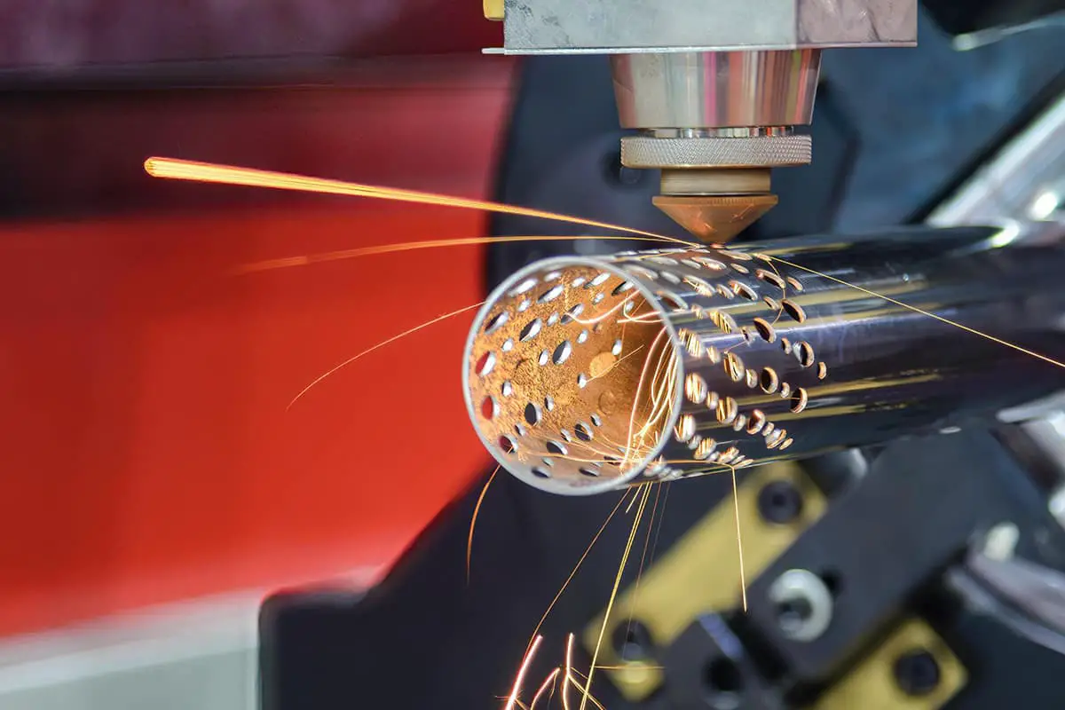
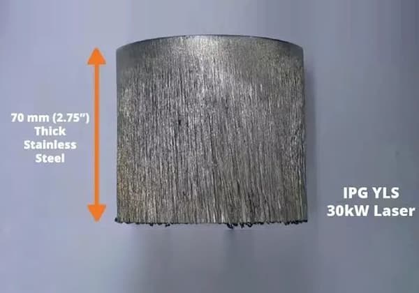
V. Laser Cutting Technology
Laser cutting is a novel thermal cutting method and is the rising star for cutting stainless steel. It utilizes the high energy of a laser beam to thermally cut workpieces. This method can be used for cutting both metallic and non-metallic materials, and some refer to the laser beam as the “cutting blade,” which is not an exaggeration.
In industrial production, common laser cutting methods can be categorized by cutting mechanisms into laser vaporization cutting, laser melting cutting, and laser oxygen cutting. A comparison of the energy density of several thermal cutting methods is shown in Table 6-19. From the table, it is evident that laser cutting possesses the highest energy density.
Table 6-19: Comparison of Energy Densities of Several Thermal Cutting Methods
Cutting Methods
Energy Density (W/cm²)
Oxygen-Fuel Gas Flame Cutting
5 × 10⁴
Plasma Arc Cutting
105 ~ 1.8 × 10⁶
Laser Cutting
(Continuous)
10 ~ 106
(Pulsed)
104 ~ 1010
Characteristics of Laser Cutting
Minimal Thermal Deformation during Cutting
Due to its high cutting energy density, it achieves precision cutting with minimal deformation of the workpiece, eliminating the need for additional machining before use.
High Cutting Surface Quality
The cutting precision can reach as small as 0.1 to 0.2mm, with a cutting surface roughness of around a dozen micrometers (Ra). The kerf is very narrow, especially with a heat-affected zone width of only 0.01 to 0.1mm, which does not affect the material’s properties.
High Cutting Speed
When using a 2kW laser cutter to cut steel plates less than 10mm thick, the cutting speed can match that of plasma arc cutting.
Versatility in Cutting Various Materials
It can cut not only steel and non-ferrous materials but also non-metallic materials such as plastic, leather, and fabric.
Favorable Cutting Environment
During cutting, there is no strong radiation, noise, or environmental pollution, thus creating a better working environment for the operator’s health.
Comparison of the performance of laser cutting with oxy-acetylene or flame cutting and plasma arc cutting can be found in Table 6-20.
Table 6-20: Comparison of Cutting Performance of Various Cutting Methods
Cutting Method
Gas Cutting (Equal Pressure Acetylene Cutting Nozzle)
Plasma Arc Cutting (Nitrogen Plasma Arc 230A)
Laser Cutting (CO2, Gas Laser, 1kW)
Heat Source
Iron-Oxygen combustion heat
Electrical energy
Light energy
Main Applicable Materials
Low carbon steel, low alloy steel
Low carbon steel, low alloy steel, stainless steel, and other non-ferrous metals
Various steels, most non-ferrous metals, as well as ceramics, plastics, wood, leather, and other non-metals
Kerf Width
Medium
Large
Very small
Cutting Dimension Accuracy
Poor (deviation 1-2mm)
Fair (deviation 0.5-1.0mm)
Very high (deviation 0.1-0.2mm)
Verticality of Cutting Surface
Not significant
Large
Small
Roughness of Cutting Surface
Generally
Good
Good
Melting Depth of Cutting Surface Edge
Not significant
Relatively large
Small
Depth of Heat Affected Zone
Significant
Medium
Small
Cutting Speed (mm/min)
Plate Thickness (mm)
<1
1
1
>5000
2
1
1
3500
6
600
3700
1000
12
500
2700
300
25
450
1200
—
50
300
250
—
>100
<150
—
—
Cutting Equipment and Processes
The cutting equipment includes CO2 gas lasers and yttrium aluminum garnet solid-state lasers, with their main technical specifications outlined in Table 6-21.
Table 6-21: Types of Laser Cutters and Key Technical Parameters
Types
Wavelength/μm
Oscillation Form
Output Power Range
Solid-state
Yttrium Aluminum Garnet
1.065
Continuous
5 ~ 750 W
Gas
CO2
10.63
Continuous
1 W ~ 1.5 kW
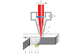
The types of assist gases vary with different materials. In the case of cutting flammable materials and metals where oxidation needs to be avoided, inert or neutral gases are used. For the cutting of general metal materials, oxygen can be used. Laser oxygen cutting is commonly used for cutting metal materials such as carbon steel, stainless steel, titanium and titanium alloys, aluminum, and aluminum alloys.
Laser oxygen cutting is similar to oxy-fuel flame cutting, where laser energy is used to heat the material to its ignition point and then burns in a stream of oxygen. The resulting molten slag is then removed from the cut by the oxygen stream.
The additional heat from the oxidation reaction significantly improves cutting speed and quality. For metals that can be completely oxidized, the cutting speed can be increased by about 10 times compared to oxy-fuel flame cutting. A typical schematic of a laser oxygen cutting torch is shown in Figure 6-16.
The process parameters for laser oxygen cutting of stainless steel can be found in Table 6-22.
Figure 6-16: Schematic diagram of a laser cutting torch
Table 6-22: Characteristics and Applications of Laser Oxygen Cutting for Stainless Steel
Thickness of Workpiece (mm)
Laser Power (W)
Cutting Speed (cm/min)
Cutting Gas
Characteristics and Applications
0.5
250
450
Oxygen
No deformation, material saving, labor saving. Used in the manufacturing of aircraft parts, helicopter rotor components, and similar parts.
2
250
25
3.175
500
180
1
1000
800
1.57
1000
456
6
1000
80
4.8
2000
100
6.3
2000
150
12
2000
40
Due to the advantages of high cutting precision, high quality, and fast cutting speed, laser cutting machines are widely used both domestically and internationally. Manual and ordinary mechanical laser cutting machines have not yet entered the industrial practical stage, and all current applications utilize systems controlled by numerical control (NC).
The main components of a CNC laser cutting machine include a gantry frame, laser, optical system, laser cutting head, CNC control and drive system, gas supply system, smoke exhaust and dust removal system, among others.
Well-known welding and cutting equipment manufacturers both domestically and abroad are capable of producing high-quality CNC laser cutting equipment, with the maximum thickness for cutting stainless steel reaching up to 16mm.
Development of Laser Cutting
Currently, yttrium-aluminum-garnet solid-state lasers typically have a power of several hundred watts (mainly used for welding) and can only cut thin metal sheets with a thickness of 1-2mm.
Recently, the United States has developed a new type of yttrium-aluminum-garnet solid-state laser, which can generate a laser beam on the workpiece with an energy density 40 times higher than that of conventional structural lasers, greatly enhancing cutting capability. It can cut through superalloy materials up to 38mm thick or perforate metal parts 25.4mm thick (with a piercing time of only 2 seconds).
CO2 gas lasers generally have an output power of less than 1.5kW and can be used to cut carbon steel and various non-ferrous metals with a thickness of less than 10mm. Japan has developed a 5kW CO2 gas laser, with a wavelength approximately half of that of CO2 gas lasers and an energy density four times greater than the latter, enabling it to cut thick plates.
In order to promote the application of laser cutting technology, significant progress has been made in cutting equipment. There are fixed cutting torches and platform-moving cutters. The platforms have 2-5 degrees of freedom, and platform movement utilizes numerical control and pre-programmable methods, and can be connected to a computer-aided design (CAD) system.
The cutting machine developed in the UK is a CO2 laser cutting device that moves on a gantry, also numerically controlled. The laser cutting head can move in five degrees of freedom (linear motion along the X, Y, Z coordinates, rotation, and tilt), enabling cutting in three directions.
Laser cutting is widely used for cutting stainless steel, titanium and titanium alloys, aluminum and aluminum alloys, and superalloys. It is extensively applied in the nuclear industry and aerospace industry, and recently, laser cutting technology has also begun to be used in cutting automobile body panels, operated by robots.
VI. Water Jet Cutting Technology
I. Cutting Principle
Water jet cutting is a new type of cold processing technology that can be used in harsh and fire-prohibited environments, and has received widespread attention. It integrates mechanical, electronic, computer, and automatic control technologies, representing a high-tech achievement, and has emerged as a new material processing method in recent years.
The principle of water jet cutting involves using high-pressure pure water or liquid slurry with cutting abrasives, which are ejected through a cutting nozzle to form a high-density liquid column, cutting the workpiece directly through impact. Depending on the water pressure, it can be classified into low-pressure and high-pressure water jet cutting. Figures 6-17 and 6-18 illustrate the process principles of water jet cutting.
Figure 6-17: Schematic diagram of low-pressure water jet cutting
Abrasive supply
Storage tank
Workpiece to be cut
Cutting gun
Pressurized storage tank
Figure 6-18 Schematic diagram of high-pressure water jet cutting principle
II. Cutting Characteristics
Water jet cutting technology exhibits the following characteristics:
High water jet cutting pressure
The water jet pressure ranges from tens to hundreds of megapascals, generating tremendous jet energy density at 2 to 3 times the speed of sound to cut objects. The temperature rise at the cut of the workpiece is very low, generally not exceeding 100°C, which is the most prominent advantage compared to other thermal cutting processes.
This eliminates the possibility of workpiece deformation, thermal impact zones, and structural changes at the cut, making it safe and reliable for use in fire-prohibited environments such as offshore oil drilling platforms, refineries, large oil tanks, and oil and gas pipelines.
Excellent quality of water jet cutting
The cut surface is smooth, free from burrs and oxide residues, and the gap of the cut is very narrow, typically controlled within 0.1mm using pure water for cutting, and between 1.2 to 2.0mm with added cutting abrasives. The cut does not require secondary processing, simplifying the machining process.
Wide range of cutting thickness
Water jet cutting has a wide range of cutting thickness, with a maximum cutting thickness exceeding 100mm. For special steel plates with a thickness of 2.0mm, the cutting speed can reach 100cm/min. Although the cutting speed of water jet cutting is slightly lower than that of laser cutting, it does not generate a large amount of cutting heat during the cutting process, making water jet cutting more advantageous in practical applications.
Wide range of cutting materials
This cutting method is suitable not only for metals and non-metals but also for the processing of composite materials and heat-sensitive materials.
Excellent operating environment
During water jet cutting, there are no radiation, no splashing particles, and no dust, avoiding environmental pollution. Even in abrasive water jet cutting, the dust and cutting debris can be directly washed away by the water flow into a collector, ensuring the operator’s health. It can be considered as an environmentally friendly machining method.
Due to the aforementioned advantages, water jet cutting has broad prospects in industries such as aerospace, nuclear energy, petroleum, chemical engineering, underwater engineering, and construction.
Cutting Process
Cutting Methods
Currently, there are two methods of water jet cutting: low-pressure and high-pressure water jet cutting.
Low-pressure water jet cutting involves pre-mixing high-pressure water (14~69MPa) and cutting abrasives in a pressurized tank, and then delivering the mixed abrasive slurry through a hose directly to the cutting gun for the cutting process, as shown in Figure 6-17. The workpiece to be cut can be cut 500m away from the cutting power source or underwater.
High-pressure water jet cutting involves separately transporting high-pressure water (greater than 240MPa) and dry abrasives through their respective hoses, then mixing them in the mixing chamber of the cutting gun to complete the cutting process of the workpiece, as shown in Figure 6-18. The workpiece to be cut is generally located near the cutting power source.
When low-pressure and high-pressure water jet cutting are performed under the same conditions, the consumption of water and cutting abrasives in the former is only 1/8-1/3 of the latter.
From the perspective of the structure of the cutting gun, the cutting gun of low-pressure water jet cutting is relatively simpler. In terms of energy consumption, low-pressure water jet cutting consumes less energy. Therefore, low-pressure water jet cutting is currently the most effective cutting process.
Cutting Abrasives
The abrasives used in water jet cutting mainly include diamond, olivine, garnet, copper smelting slag, and oxides. Among them, copper smelting slag is relatively ideal. Firstly, its price is low, only 1/8~1/10 of the price of steel sand; more importantly, its cutting speed is 30% faster than diamond. This is because the particles of copper smelting slag are relatively sharp.
During the cutting process, when they collide with the workpiece, they are broken, forming more cutting edges. In addition, when diamond is used for water jet cutting, the cutting abrasives are easily embedded in the base material, which can adversely affect certain properties of the cutting area, such as the mechanical properties of the weld joint. Using copper smelting slag as the cutting abrasive can overcome this flaw.
The particle size of the cutting abrasive is generally required to be 0.2~1.5mm, which mainly depends on the nozzle diameter of the cutting spray gun. The cutting abrasives can be recycled and reused 2-3 times, then sieved to remove excessively fine abrasives.
Materials for Cutting Nozzles
For cutting nozzles, besides having sufficient toughness and hardness, the most important aspect is good wear resistance, which effectively reduces the wear of the cutting nozzle and thereby improves its service life.
Due to the wear of the inner diameter of the nozzle, the gap of the cut will widen, leading to a decrease in the perpendicularity of the cut section. Tungsten, silicon, or hard alloys are usually chosen as materials for cutting nozzles, but their service life is not ideal. Currently, it is considered more suitable to use sapphire as the material for the nozzle.
Cutting Process
Refer to Table 6-23 for the commonly used cutting materials and their cutting process parameters for water jet cutting.
Table 6-23: Water Jet Cutting Speeds for Common Materials
Materials
Cutting Thickness
Water Pressure/MPa
Nozzle Diameter/Water/Abrasive/mm
Cutting Speed/(m/min)
Carbon Steel
12
350
0. 25 / 0. 76
0. 4
50
0. 1
Stainless Steel
13
350
0. 25 / 0. 76
0. 4
25
0. 2
Titanium
3. 2
350
0. 25 / 0. 76
0.8
6. 4
0.6
Aluminum
12
350
0. 25 / 0. 76
0. 6
100
0. 12
Ductile Iron
15
350
0. 25 / 0. 76
0. 4
Composite Material
12
309
0.25
3. 5
Gypsum Board
15
294
0. 15
20
Rubber
15
377
0. 17
12
Silicone Rubber
12
377
0. 12
3
Hard Rubber
19
309
0. 25
6
Cloth
20
309
0. 18
3
Fabric
20
377
0.2
6
Leather
1
343
0. 15
30
Experiments were conducted on the cutting of austenitic stainless steel plates of different thicknesses using the low-pressure water jet cutting process. The cutting nozzle diameter was 1mm, water pressure was 69MPa, and the relationships between cutting speed, cutting depth, and the amount of abrasive used are depicted in Figures 6-19 and 6-20 (material: 18-8 stainless steel, plate thickness: 3mm).
Figure 6-19: Relationship between cutting speed and cutting depth
Figure 6-20: Relationship between cutting depth and abrasive usage
As water jet cutting has evolved into a precision machining process, it demands high precision from the equipment, making the water jet cutting machine a precision machining tool.
The technical characteristics of this equipment are equivalent to those of a precision laser cutting machine. It consists of a high-pressure water jet generator (pressurization device), water jet cutting head, CNC cutting platform, CNC controller system, as well as a computer, and sand control auxiliary equipment.
As the founder of MachineMFG, I have dedicated over a decade of my career to the metalworking industry. My extensive experience has allowed me to become an expert in the fields of sheet metal fabrication, machining, mechanical engineering, and machine tools for metals. I am constantly thinking, reading, and writing about these subjects, constantly striving to stay at the forefront of my field. Let my knowledge and expertise be an asset to your business.
Ever wonder why stainless steel laser cutting sometimes produces uneven edges or discoloration? This article dives into common issues like burr formation and surface color changes, explaining their causes and…
How can we ensure our laser cutting process for stainless steel is flawless every time? This article explores essential techniques and adjustments to optimize laser cutting quality, focusing on issues…
Ever wondered how to achieve perfect laser cuts on thick stainless steel? This article delves into essential tips for laser cutting plates over 25mm thick. It covers crucial factors like…
1. Main causes of dimensional error of parts caused by flame cutting The main causes of errors in NC cutting and blanking include thermal deformation of the steel plate, operator…
Are you struggling with commissioning your 10kW+ fiber laser cutting machine? This article offers practical solutions to common issues faced during the setup process, ensuring optimal performance and efficiency. Learn…
Ever wondered how to achieve precise cuts on thick stainless steel plates using lasers? This article dives into the essential debugging methods and skills needed for optimal laser cutting performance.…
Imagine cutting through metals and materials with a beam of light. Laser cutting technology makes this a reality, handling a wide range of substances from sturdy stainless steel to delicate…
Imagine cutting through 230mm thick stainless steel like slicing through butter. Ultra-high power fiber lasers, ranging from 10kW to 40kW, revolutionize the cutting industry with unparalleled speed and precision. This…
Ever wondered why laser-cut sheet metal sometimes falls short of perfection? This article addresses common laser cutting problems, like burrs on workpieces and incomplete cuts, and offers practical solutions. By…