I. Overview
A comprehensive count of all parts and materials needed for the electrical control cabinet is carried out, and a summary list of purchased finished parts, a list of standard parts, a quota table for the consumption of main materials, and a quota table for auxiliary materials are listed by category.
This facilitates procurement personnel and production management departments to prepare materials according to equipment manufacturing needs, prepare for production, and facilitate cost accounting.
The basic idea of electrical control cabinet design is a logical thinking. As long as it conforms to the laws of logic control, ensures electrical safety, and meets the requirements of the production process, it can be said to be a good design.
However, in order to meet the manufacturing and use requirements of electrical control equipment, a reasonable electrical control process design must be carried out.
These designs include the structural design of the electrical control cabinet, the overall configuration diagram of the electrical control cabinet, the design of the main connection diagram, and the design of the electrical assembly diagram and connection diagram of each part.
It also includes some component catalogs, incoming and outgoing line numbers, and main material lists and other technical documents.
II. Overall Configuration Design of the Electrical Control Cabinet
The task of the overall configuration design of the electrical control cabinet is to divide the control system into several components according to the working principles and control requirements of the electrical schematic diagram (these components are all called components).
Then, according to the complexity of the electrical control cabinet, each component is divided into several modules.
Then, according to the wiring relationship of the electrical schematic diagram, the incoming and outgoing line numbers of each part are sorted out, and their connection methods are adjusted.
The overall configuration design is expressed in the form of the general assembly diagram and the main connection diagram of the electrical system, and the diagram should reflect the position of the main components of each part and the connection relationship, wiring method, and the use of wiring ducts, pipelines, etc.
The main assembly diagram and connection diagram of the electrical control cabinet (they can be divided or combined as needed) are the basis for designing and coordinating each part into a complete system.
The overall design should make the entire electrical control system centralized and compact, and at the same time, under the condition of allowing space, place the heat-generating components and electrical components with large noise and vibration as far as possible from other components or isolate them.
For large-scale equipment with multiple workstations, the convenience of operation in two places should also be considered. The main power switch of the control cabinet and the emergency stop control switch should be placed in a convenient and obvious position.
Whether the overall configuration design is reasonable or not is related to the manufacturing and assembly quality of the electrical control system, and it will also affect the realization of the performance of the electrical control system and its working reliability, operation, debugging, maintenance, and other work convenience and quality.
2.1 The division of electrical control cabinet components is necessary because various electrical components have different installation positions. When forming a complete electrical control system, it is necessary to divide the components.
The principles for dividing components are:
(1) Combine components with similar functions;
(2) Minimize the number of connections between components and put control electrical appliances with close wiring relationships in the same component;
(3) Separate strong and weak electric controllers to reduce interference;
(4) For neatness and beauty, you can combine electrical appliances with similar dimensions and weights;
(5) For the convenience of checking and debugging the electrical control system, combine frequently adjusted, maintained, and easily damaged components.
2.2 While dividing the components of the electrical control cabinet, the wiring methods between the components, between the electrical boxes, and between the electrical box and the controlled device need to be resolved.
The connection methods between various parts and components of the electrical control cabinet should generally follow the following principles:
(1) The incoming and outgoing lines of switch appliances and control boards generally use terminal heads or terminal noses for connection, which can be selected according to the size of the current and the number of incoming and outgoing lines.
(2) Between the electrical cabinet, control cabinet, cabinet (table) and the equipment they control, use terminal strips or industrial connectors for connection;
(3) Weak electric control components and printed circuit board components should use various types of standard connectors for connection;
(4) The connection between the components in the electrical cabinet, control cabinet, and cabinet (table) can be directly connected using the terminal of the component itself; the transition connection line should be connected by the terminal strip for transition connection, and the terminal should be treated with the corresponding specification of the terminal.
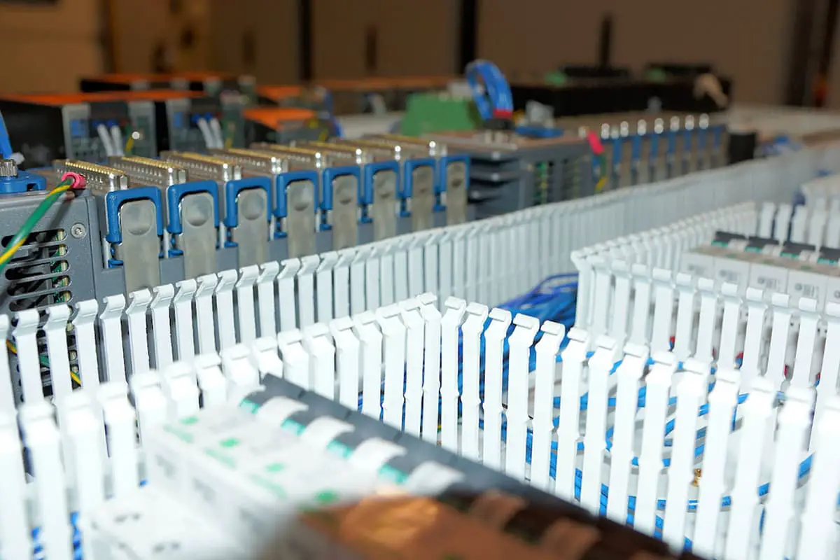
III. Design and Drawing of Electrical Component Layout
The layout of electrical components is a combination of some electrical components according to certain principles.
The design basis of the layout of electrical components is the principle diagram of components and the division of components, etc. The design should follow the following principles:
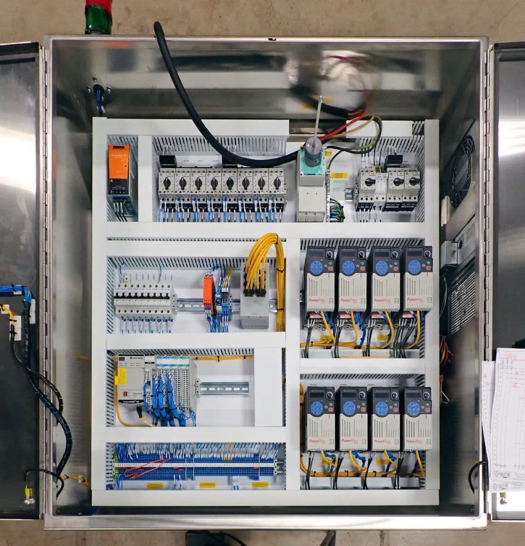
(1) The arrangement of electrical components in the same component should pay attention to the installation of large-volume and heavy electrical components at the bottom of the electrical board, while the heat-generating components should be installed at the top or rear of the electrical control cabinet.
However, thermal relays should be placed at the bottom because the outgoing end of the thermal relay is directly connected to the motor which is convenient for outgoing, and its incoming end is directly connected to the contactor, which is convenient for wiring and makes the wiring shortest, and it is conducive to heat dissipation.
(2) Separate strong and weak electricity and pay attention to shielding to prevent external interference.
(3) The installation of electrical components that need regular maintenance, overhaul, and adjustment should not be too high or too low, and the installation location of manual operation switches and instruments that need to be frequently monitored should comply with the principles of ergonomics.
(4) The arrangement of electrical components should consider safety clearance, and make it neat, beautiful, and symmetrical. Electrical components with similar sizes and structures can be placed together to facilitate processing, installation, and wiring.
If the trunking wiring method is adopted, the spacing between each row of electrical appliances should be appropriately increased to facilitate wiring and maintenance.
(5) After the position of each electrical component is determined, the electrical layout can be drawn. The electrical layout is drawn based on the outline of the electrical components, that is, based on its axis, and the spacing dimensions of each component are marked.
The installation dimensions and tolerance range of each electrical component should be marked according to the product instruction manual to ensure the processing quality of the installation plate and the smooth installation of each electrical appliance.
The electrical components in the large electrical cabinet should be installed between the two installation beams, which can reduce the weight of the cabinet, save materials, and facilitate installation.
Therefore, the longitudinal installation size should be calculated during the design.
(6) In the design of the electrical layout, the method of incoming and outgoing lines, terminal strips, connectors, or connectors should also be selected according to the number of incoming and outgoing lines of this component, the specifications of the used wires, and the outgoing line location, etc., and the incoming and outgoing line connection numbers should be marked in a certain order.
IV. Drawing of Electrical Component Connection Diagram
The electrical component connection diagram is drawn based on the component electrical principle and electrical component layout.
It represents the connection relationship of the complete device and is the basis for electrical installation, maintenance, and line checking. The connection diagram should be drawn according to the following principles:
(1) The drawing of the connection principle diagram should comply with the provisions of GB6988.6—1993 “Drawing of Control System Function Table”;
(2) All electrical components and their leads should be marked with text symbols and connection numbers consistent with the electrical schematic diagram.
The compilation of project codes, terminal numbers, and wire numbers in the schematic diagram should comply with GB5094-1985 “Project Codes in Electrical Technology”, GB4026-1992 “Identification and Application of General Letter Number Systems for Wiring Terminals and Specific Wire Ends of Electrical Equipment”, and GB4884-1985 “Insulated Wire Marking” and other regulations;
(3) Different from the electrical schematic diagram, in the connection diagram, all parts of the same electrical component (contacts, coils, etc.) must be drawn together;
(4) The electrical connection diagram is always drawn with thin lines. The wiring methods are divided into front and back panels. Generally, the front panel wiring method is used.
For simple electrical control components, if the number of electrical components is small and the connection relationship is not complicated, you can directly draw the connection between components.
For complex components with many electrical components and complex wiring, generally use trunking. As long as the wiring number is marked on each electrical component, there is no need to draw the connection between each component;
(5) The connection diagram should indicate the model, specification, cross-sectional area, and color requirements of various wires used for wiring;
(6) When the component is connected to the external circuit, the large cross-section wire incoming and outgoing line should be connected with the connector, and the others should be connected through the terminal strip.
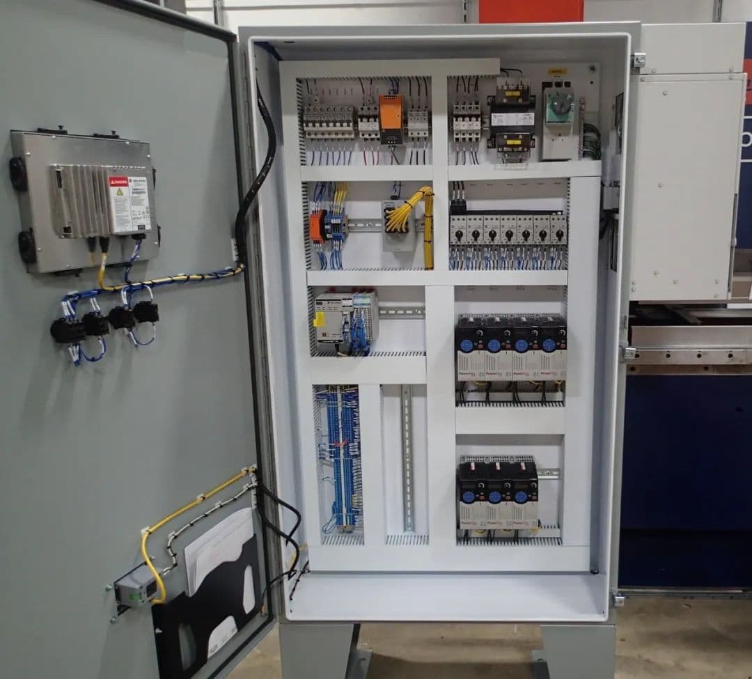
V. Design of Electrical Control Cabinet and Non-standard Part Drawings
Electrical control devices usually need to make separate electrical control cabinets and boxes. Their design needs to consider the following aspects:
(1) Determine the overall size and structural type of the electrical box and cabinet according to the operation needs and the size of various electrical components in the control panel, box, and cabinet. In non-special cases, the overall size of the electrical control cabinet should conform to the basic size and series of structures;
(2) Based on the overall size and structural type of the electrical control cabinet and installation size, design the installation bracket in the box and mark the installation hole, installation bolt, and grounding bolt size, and also indicate the matching method. The material of the cabinet and box should generally be selected from special profiles for the cabinet and box;
(3) According to the requirements for convenient installation, operation, and maintenance on site, design the opening method and type of the electrical control cabinet;
(4) In order to facilitate the ventilation and heat dissipation of the electrical appliances in the control cabinet and box, design ventilation holes or ventilation slots in the appropriate parts of the box, and when necessary, design forced ventilation devices and ventilation holes at the top of the cabinet;
(5) To facilitate the transportation of the electrical control cabinet, a suitable lifting hook should be designed or movable wheels should be designed at the bottom of the box.
VI. Wrap It Up
In summary, based on the above requirements, you should first sketch the outline sketch of the electrical control cabinet, estimate the dimensions of each part, and then draw the outline diagram to scale, and then further consider adjusting the size proportions from symmetry, beauty, and convenience of use.
After the appearance of the electrical control cabinet is determined, the structure design of each part of the control cabinet is carried out according to the above requirements, and the assembly diagram of the cabinet and the parts diagrams of each door, control panel, bottom plate, installation bracket, decorative strip, etc. are drawn, and the processing requirements are indicated.
Then, an appropriate door lock is selected for the electrical control cabinet as needed. Of course, the shapes and structures of electrical cabinets vary.
In the design of the cabinet, we should pay attention to absorbing the advantages of various types.
For non-standard electrical installation parts, part drawings should be drawn according to the requirements of mechanical part design, and tolerance requirements should be marked for all matching dimensions, and processing requirements should be stated.
Finally, based on various drawings, a comprehensive count of all parts and materials needed for the electrical control cabinet is carried out, and a summary list of purchased finished parts, a list of standard parts, a quota table for the consumption of main materials, and a quota table for auxiliary materials are listed by category.
This facilitates procurement personnel and production management departments to prepare materials according to equipment manufacturing needs, prepare for production, and facilitate cost accounting.