What makes specialty smelting so crucial in modern industry? This process is essential for producing high-quality steels and alloys used in demanding fields like aerospace and electronics. Conventional methods fall short of meeting the stringent requirements of these applications, necessitating advanced techniques such as induction melting, electro-slag metallurgy, and vacuum arc remelting. In this article, you will learn about the various specialty smelting methods and their unique advantages, helping you understand their pivotal role in manufacturing superior metal products.
Specialty smelting is a special and effective method for producing special steel, high-temperature alloys, precision alloys, and high-alloy steels.
Metal materials represented by steel have been widely used in the national economy, national defense construction, scientific and technological fields, etc.
The rapid progress in contemporary electronic technology, aerospace technology, navigation and energy technology and other fields has raised increasingly high requirements for the quality and variety of steel and alloys.
For example, it is required that steel or alloys can work reliably under the environment of high temperature, high pressure, high speed, dynamic load, high radiation, and highly corrosive medium.
However, conventional smelting methods such as converter, open hearth furnace, and arc furnace are difficult to meet actual requirements, and cannot provide products of such high quality, which requires the use of special smelting methods.
Common specialty smelting methods include induction melting, electro-slag metallurgy, plasma arc melting, vacuum arc remelting, and electron-beam melting process.
(1) Induction Melting
Induction melting is a method of heating and melting metals using the principle of electromagnetic induction.
According to frequency, it can be divided into power frequency furnace, medium frequency furnace, and high frequency furnace; according to atmosphere and structure, it can be classified into vacuum induction furnace and plasma induction furnace and other furnaces for different purposes.
Power frequency furnaces are mainly used for smelting cast iron, high-frequency furnaces are mainly used for laboratory research, while medium-frequency furnaces are mainly used for producing high-quality steel and alloys, with advantages of fast melting speed, high production efficiency, strong adaptability, flexible use, good electromagnetic stirring effect, and convenient startup operation.
Currently, induction furnace smelting has become an important method for producing special alloys such as special steel, precision alloys, electric heating alloys, high-temperature alloys, and corrosion-resistant alloys.
(2) Electro-slag Metallurgy
Electro-slag metallurgy is a special smelting method that uses the heat generated by the slag resistance caused by the current passing through the liquid slag to heat and refine the metal.
Its core is electro-slag remelting (ESR), which aims to further purify steel and alloys and improve the crystal structure of ingots on the basis of initial refining, thereby obtaining high-quality metal products.
Electro-slag remelting is suitable for the production of medium and large forgings. The product after remelting has low phosphorus and sulfur content, low non-metallic inclusions, dense structure of the remelted ingot and casting without shrinkage, greatly improving the quality of the product, as well as its mechanical properties, processing performance, and usability.
(3) Vacuum Arc Melting
Vacuum arc melting can form a low oxygen potential and high-temperature melting condition, so it was used as early as the last century for melting refractory or oxidizable metals such as platinum, tantalum, and tungsten.
With the development of the mechanical industry, the vacuum consumable electrode arc remelting method has been successfully applied to the production of titanium and its alloys, precision alloys, high-temperature alloys, and refractory metals.
This smelting method developed rapidly in the 1940s and 1950s, with increasingly large capacities. To date, in specialty smelting, vacuum arc melting is still one of the main methods for remelting and refining.
(4) Electron-beam Melting
Electron-beam remelting (EBM) is a smelting method that uses an electron gun to emit high-speed electron beams as a heat source to melt metals under conditions of high vacuum.
It started with the smelting of refractory metals (tantalum, niobium, hafnium, tungsten, molybdenum, etc.) and has now expanded to the production of semiconductor materials, high-performance magnetic alloys, and some special steels such as bearing steel, corrosion-resistant stainless steel, and ultra-low carbon pure iron.
In addition, electron beam remelting furnaces can also be used for smelting certain heat-resistant alloys, especially tungsten- and molybdenum-containing alloys with niobium or tantalum as the main component.
(5) Plasma Arc Melting
Plasma melting is a new smelting method that uses a plasma arc as a heat source to melt, refine, and remelt metals.
The potential advantages of using a plasma arc as a metallurgical heat source are: concentrated energy, high temperature (5000-300,000 K), fast ion flow rate (100-500 m/s), rapid heating and rapid reaction, etc. The gas is in an ionized state, and the reaction activity is strong.
The gas can be selected according to needs, such as using reducing gases (hydrogen, carbon monoxide, alkanes, and alkenes, etc.) to directly reduce or refine the charge, and it can also deoxidize to make the ingots free of residual deoxidation products.
Under the action of high-temperature plasma arc, impurities such as S, P, Pb, Bi, Sn, and As are easy to volatilize. It can melt metal materials and also melt non-metallic materials.
1.2 Main Products Produced by Special Smelting Plant
Special smelting is a special and effective method for producing advanced alloys such as special steel, high-temperature alloy, precision alloy, high-alloy steel, refractory metals and alloys, titanium and titanium alloys, electric heating alloys, etc.
(1) Precision Alloy, a kind of metal and alloy with special physical properties, is mainly used to manufacture important materials such as precision instruments, controls, telemetry, electrical appliances, accessories and electronic devices in aerospace, as well as sensors and transducers in weapon systems, based on its physical properties rather than structural components.
In China, the letter “J” is used before a number to indicate its alloy category; for example, “1J” represents soft magnetic alloy, “2J” represents permanent magnetic alloy, “3J” represents elastic alloy, “4J” represents thermal expansion alloy, “5J” represents thermal bimetal, and “6J” represents resistance alloy.
(2) High-temperature alloy (high temperature-resisting alloy or heat-resisting superalloy ) is an important metal material for aviation gas turbines, ship gas turbines, and rocket engines. It has higher resistance to creep deformation and creep fracture, as well as resistance to corrosion and thermal shock.
1.3 Quality Evaluation Indicators for Steel and Alloy Melting
(1) Component Control:
In addition to controlling C, Mn, Si, P, S, which are usually controlled in steel production, component control also includes the control of alloy elements such as Cr, Ni, Mo, W, Nb, V, Al, Ti, and trace elements B, Ce, La, Zr, Mg, Ca, Hf, Y, Sm. Whether the composition can be optimally controlled depends largely on the smelting process.
(2) Purity:
The purity of steel and alloys refers to the amount of harmful impurities and gas content, mainly including the following aspects.
1. Non-metallic impurities
Non-metallic impurities usually refer to S, P, Ce, Br, I, etc. Different steel grades have different requirements for S and P content.
For example, for ordinary steel, w(S)≤0.055%, w(P)≤0.045%; for high-quality steel, w(S)≤0.045%, w(P)≤0.040%; for alloy steel, both S and P are less than 0.04%; for advanced high-quality steel, w(S)≤0.030%, w(P)≤0.035%; while for some high-temperature alloys, w(S)≤0.030%.
For Ce, Br, I, etc., some technical standards stipulate that they should be lower than 0.0025%.
2. Gas
Generally, the lower the content of oxygen, hydrogen, and nitrogen in steel and alloys, the better their performance.
3. Non-metallic inclusions
The influence of non-metallic inclusions on the performance of steel and alloys is not only related to their quantity, but also to their type, size, morphology, and distribution.
Therefore, the content and distribution status of non-metallic inclusions are one of the important indicators for evaluating the quality of steel and alloys, and conventional inspection uses standard grade comparison method.
4. Metal impurities
Metal impurities mainly refer to Pb, Sn, As, Sb, Bi, and other trace element impurities in steel and alloys. The content of metal impurities has a significant impact on the performance of steel and alloys.
5. Cast structure
The cast structure of steel and alloy ingots has an important influence on the hot working plasticity of ingots and the mechanical properties of steel.
The cast structure of good metallurgical products should have the following conditions: the specifications meet the requirements; the surface quality is good; the shrinkage is small; the ingot is dense; the composition and organizational structure are uniform, the degree of segregation is small; the crystal structure is good.
1.4 Influence of Process on the Microstructure and Properties of Steel and Alloys
(1) Component control affects the performance of steel and alloys.
Different smelting methods have different degrees of component control, with vacuum arc furnaces being better at controlling easily oxidizable elements and electroslag remelting having less loss of volatile elements.
(2) Purity affects the performance of steel and alloys.
Vacuum melting has low harmful metal impurities and oxygen content, and electroslag remelting has good desulfurization ability and removal of oxide inclusions.
(3) Controlling the microstructure affects the performance of steel and alloys.
Electroslag remelting ingots have a columnar crystal axis development and low porosity segregation.
2. Induction Furnace Melting
2.1 Induction Furnace Working Principle and Equipment
2.1.1 Working Principle of Induction Furnace
All types of induction furnaces, regardless of whether they are core or coreless, as well as whether they operate at low frequency, intermediate frequency, or high frequency, their basic circuit is composed of a variable power supply, capacitors, an induction coil, and metal furnace materials in the crucible (Figure 2-1).
(1) Principle of Induction Heating
The principle of induction heating is based on the following two basic laws of electricity: first, Faraday’s law of electromagnetic induction.
E=B·L·v·sin∠(v·B) (2-1)
where L is the length of the wire in the magnetic field;
(v·B) is the angle between the direction of the magnetic induction strength and the velocity direction.
The other fundamental law is Joule-Lenz law. This law is also known as the principle of electrical thermal effect. Joule-Lenz law can be expressed in the form of equation (2-3):
Q = I2 R t (2-2)
where Q is the Joule-Lenz heat, in J; I is the current intensity, in A;
R is the resistance of the conductor, in Ω; t is the time when the conductor is energized, in s.
When an alternating current with a frequency of f flows through the induction coil of a coreless induction furnace, an alternating magnetic field is generated in the space surrounding the induction coil and its surroundings.
The polarity, magnetic induction strength, and frequency of the alternating magnetic field change with the alternating current that generates this alternating magnetic field. If the crucible is lined with the induction coil and filled with metal furnace materials, part of the magnetic field lines of the alternating magnetic field will pass through the metal furnace materials.
The alternation of the magnetic field lines is equivalent to the relative motion of the cutting magnetic field lines between the metal furnace materials and the magnetic field lines.
Therefore, an induced electromotive force (E) will be generated in the metal furnace materials, and its magnitude can be determined by the following equation:
E = 4.44 Ф· f · n (2-3)
where Ф is the magnetic flux of the alternating magnetic field in the induction coil, in Wb;
f is the frequency of the alternating current, in Hz;
n is the number of turns of the loop formed by the furnace materials, usually n=1;
From the above equation, it can be seen that to generate a larger induced voltage in the furnace materials, theoretically increasing the magnetic flux, frequency, and number of turns can be used.
However, since the magnetic field lines generated after the induction coil is energized are forced to pass through air (in the case of a coreless induction furnace), and air has a high magnetic reluctance, the magnetic flux is relatively small, making it difficult to increase the magnetic flux, and the number of turns of the furnace materials is generally equal to l.
Therefore, in order to increase the induced voltage, it is better to use the method of increasing the frequency.
As the metal furnace materials themselves form a closed loop t, the induced current (I) generated in the metal furnace materials is:
where R is the effective resistance of the metal furnace material, in Ω;
The heating rate of the furnace material depends on the induced current, the effective resistance of the furnace material, and the energizing time. The induced current depends on the magnitude of the induced electromotive force, that is, the magnitude of the magnetic flux passing through the furnace material and the frequency of the alternating current flowing through it. The magnitude of the induced current depends on the size of the furnace material block.
(2) Electromagnetic Stirring
When an induced current flows through the furnace material, it will inevitably be subjected to electromagnetic forces, causing directional movement of the metal furnace material; that is, the “electromagnetic stirring” effect. Its benefits are as follows:
1) uniform temperature of the metal liquid.
2) Homogenization of the metal liquid.
3) Improving the kinetic conditions of physical and chemical reactions.
2.1.2 Induction Furnace Working Equipment
Induction furnaces can be divided into two types: coreless and core types, with the latter rarely used in steelmaking and will not be discussed here. As for coreless induction furnaces, they can generally be classified into three types according to the power frequency: the line-frequency furnace (with a frequency of 50 or 60Hz) which is directly connected to the power grid through a transformer and mainly used for melting cast iron; the high-frequency furnace (with a frequency range of 10KHz to 300KHz) which uses a high-frequency electronic tube oscillator and is mainly used for small laboratory research; and the medium-frequency furnace (with a frequency range of 150Hz to 10000Hz) which uses a medium-frequency generator set, tripler or thyristor static frequency converter.
The complete set of equipment for medium-frequency induction furnaces includes: the power supply and electrical control part, the furnace body, the transmission device, and the water cooling system.
2.2 Characteristics of Induction Furnace Melting
(1) Electromagnetic induction heating. As the heating method is different, induction furnaces do not require graphite electrodes necessary for electric arc heating, nor localized overheating zones under the arc, thus eliminating the possibility of electrode carbon increase. Induction furnaces can melt low-carbon steel and alloys that are difficult to melt in electric arc furnaces, creating favorable conditions for producing products with low gas content.
(2) There is a certain level of electromagnetic stirring in the molten pool. The metal stirring caused by electromagnetic induction promotes uniform composition and temperature, inclusion coalescence, growth and floatation in steel. The loss of alloy elements during the induction furnace melting process is relatively small, so the predicted composition is more accurate, which is conducive to component control and shortens the melting time.
(3) The ratio of the molten pool surface area is small. This is advantageous for reducing the loss of easily oxidized elements in the molten metal and reducing gas absorption. Therefore, induction furnaces have created relatively favorable conditions for melting high-alloy steels and alloys, especially those containing titanium, aluminum or boron. However, it is prone to form poor fluidity, low reaction strength, which is not conducive to the metallurgical reaction at the interface of slag and steel. For this reason, the requirements for raw materials in induction furnace melting are relatively strict.
(4) Convenient adjustment of input power. During the induction furnace melting process, the input power can be conveniently adjusted. Therefore, the melting temperature of the molten pool can be controlled more accurately, the furnace can be insulated, and the steel can be produced several times, creating conditions for melting products with different compositions in one batch.
(5) The same power source can supply power to several different capacity furnaces (but not at the same time), so the flexibility of induction furnaces is greater than that of electric arc furnaces in terms of smelting capacity.
(6) High thermal efficiency. The heating method of induction furnaces and small surface area result in less heat dissipation, thus the thermal efficiency of induction furnaces is higher than that of electric arc furnaces. However, the electrical efficiency of induction furnaces is lower than that of electric arc furnaces, so the total efficiency of the two types of electric furnaces is similar.
(7) Less smoke and small environmental pollution. When melting in induction furnaces, there is basically no flame or combustion products.
(8) Consumes more refractory material than electric arc furnaces and has a shorter crucible life. The requirement for refractory materials in the crucible is high, so the cost of refractory materials per ton of steel is also higher than that of electric arc furnaces.
2.3 Induction Furnace Melting Principles
2.3.1 Oxidation and Deoxidation of Elements
Oxygen exists in two states in molten steel. One is dissolved oxygen, represented by [O], and its solubility increases with the increase of temperature. The other is oxygen that exists in the form of inclusion in the molten steel. When deoxidizing elements are present in the molten steel, the dissolved oxygen in the molten steel combines with them to form oxide inclusions. The sources of oxygen in molten steel mainly include the invasion of oxygen from the atmosphere during melting and casting, oxygen brought in with raw materials, and oxygen entering from refractory materials.
(1) Deoxidation ability of elements
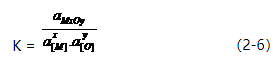
The degree of difficulty of oxidation of various elements is called the oxidation state, also known as the deoxidation ability. It refers to the residual oxygen content dissolved in the steel in equilibrium with a certain concentration of deoxidizing elements at a certain temperature and pressure. The lower the oxygen content, the stronger the deoxidation ability of this element. The general formula for the deoxidation reaction of an element is:
x[M]+y[O]=MxOy (2-5)
If metal oxides are considered to be pure substances that are not soluble in molten steel and the content of metal elements and oxygen is low in the molten steel, then we have:
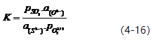
In the formula, aMxOy represents the activity of the oxide obtained by deoxidizing the element, a[M] represents the activity of the deoxidizing element in steel, and a[O] represents the activity of oxygen in steel. When the deoxidation product is a pure oxide or in a saturated state, aMxOy equals 1. When fM=1, f0=1, or fMx.f0y=constant, then,
Let KM = 1/K. Then, KM = [%M]x.[%O]y (2-8).
The magnitude of KM can be used to determine an element’s deoxidation ability. The smaller the value of KM, the stronger the element’s deoxidation ability. Figure 2-7 and Table 2-8 provide a comparison of the deoxidation abilities of elements in molten iron and nickel at a temperature of 1600℃. Generally, in molten iron at 1600℃, the order of deoxidation ability from strongest to weakest is: Ba → Ca → Ce → La → Mg → Zr → Al → Ti → B → Si → Mn → W → Fe.
(2) Deoxidation effects and influencing factors of elements
1. Affinity of elements to oxygen: The stronger the affinity of an element to oxygen, the greater its deoxidation ability, which is more advantageous for improving the deoxidation effect.
2. Physical properties of deoxidizing elements: These include the melting point, specific gravity, boiling point (vapor pressure), and solubility in steel liquid.
3. Physical characteristics of deoxidation products: The melting point, specific gravity, interfacial tension of steel liquid, the ability to form low-melting-point liquid composite oxides with high-melting-point oxides, as well as the solubility in steel liquid, all have a significant impact on the deoxidation effect.
(3) Characteristics of deoxidizing elements and composite deoxidizers:
1. Aluminum deoxidation and simultaneous deoxidation with aluminum, manganese, or silicon and manganese: Aluminum is a strong deoxidizer with high affinity to oxygen, but its deoxidation ability is lower than that of calcium, magnesium, barium, rare earth elements, and higher than that of silicon, manganese, titanium, and other elements.
2. Characteristics of calcium and calcium alloys for deoxidation: Calcium is a very strong deoxidizer and also a highly effective desulfurizing element. However, due to its low boiling point (1484℃), it exists in a vapor state in molten iron, which reduces its effectiveness. In addition, the solubility of calcium in molten iron is very low, which affects its deoxidation and desulfurization effects, thus reducing its utilization efficiency.
2.3.2 Diffusion Deoxidation and Precipitation Deoxidation
(1) Diffusion Deoxidation
Principle of diffusion deoxidation: According to the law of distribution of energy, during diffusion deoxidation, oxygen can simultaneously dissolve in both slag and steel liquid. At a certain temperature, the following equilibrium relationship exists:
(FeO) = Fe(l) + [O] (2-9)
At this time, the ratio of oxygen concentration between slag and steel liquid should be constant, that is
Factors affecting diffusion deoxidation:
a) The effect of temperature on the diffusion deoxidation efficiency. The impact of temperature on the maximum saturated oxygen content in molten iron is twofold, and the relationship is expressed by the following formula: Log [%O]saturated = -6320/T + 2.734 (2-11).
b) The influence of steel slag contact conditions.
c) The influence of slag composition.
(2) Precipitation deoxidation:
Principle of precipitation deoxidation: Precipitation deoxidation refers to the addition of elements to molten steel with an oxygen affinity greater than that of iron, with the aim of reacting with dissolved oxygen to form an oxide that is insoluble in molten steel. The oxide is then removed from the molten steel by buoyancy, thereby reducing the oxygen content of the molten steel.
Types and application range of precipitation deoxidizers: Commonly used precipitation deoxidizers mainly include pure metal deoxidizers, nickel-based deoxidizers, aluminum-based deoxidizers, silicon-manganese-based and silicon-calcium-based deoxidizers. By using composite deoxidizers containing strong deoxidizing elements such as calcium, barium, and magnesium to reduce the total oxygen content, a steel liquid with a total oxygen content of ≤0.003% can be obtained. Only through the combined use of different deoxidizers can highly pure steel be achieved.
2.3.3 Alloy Desulfurization
Essentially, alloy desulfurization involves converting dissolved sulfur in molten iron into a high-melting-point compound (such as CaS, MgS, CeS) or a sulfide oxide. The solubility of these sulfides in molten iron is much lower than that of iron sulfide, ensuring the removal or dispersion of sulfur from the steel. The main methods of desulfurization are using refining agents or slag reaction.
(1) Refining Agent Desulfurization
The basic principle of refining agent desulfurization is to use substances with a high affinity for sulfur to form sulfides. These sulfides are insoluble or have very low solubility in molten iron and have a lower density than alloy liquid. The relative affinity of various elements to sulfur can be measured by the standard free energy change of each element reacting with 1 mole of sulfur. At the same temperature, the smaller the value of the standard free energy, the greater the affinity between the element and sulfur. The relative affinity of different elements to sulfur decreases in the order of La, Ca, Ba, Mg, Mn, Fe.
(2) Slag Reaction Desulfurization
Slag reaction desulfurization can only be carried out in an alkaline induction furnace. The desulfurization process can be divided into the following three steps:
1. Sulfur ions in the metal liquid diffuse to the slag interface, and oxygen ions in the slag diffuse to the slag-steel interface;
2. The following reaction occurs at the slag interface: [S] + (O2-) = (S2-) + [O] (2-12)
3. The generated sulfur atoms diffuse into the slag, and the generated oxygen atoms diffuse into the steel. Empirically, the desulfurization reaction rate is determined by the diffusion of sulfur ions in the slag. The equilibrium constant K shown in Equation 2-12 is a constant that varies with temperature. The desulfurization capability of the slag is usually expressed by the distribution coefficient Ls, which
NO2- represents the alkalinity of the slag, and higher alkalinity is more favorable for desulfurization. However, when the alkalinity is too high, the desulfurization rate may be limited due to the increased melting point and viscosity of the slag, which is not conducive to desulfurization. When the oxygen content in the metal melt is low, the content of iron oxide in the slag is also low, which is favorable for desulfurization. Experiments have shown that there is a relationship between the equilibrium content of sulfur and oxygen in pure molten iron at 1600℃: [S]/[O] = 4. Increasing the temperature is favorable for desulfurization, not only because it increases Ls but also because it can improve the flowability of the steel slag.
2.3.4 Removal of Non-metallic Inclusions
The presence of a large number of non-metallic inclusions in steel can destroy the continuity of the steel matrix, weaken the interatomic forces, promote stress concentration, and lead to crack formation. They seriously degrade the mechanical properties of the steel, especially reducing its plasticity, impact toughness, fatigue performance, and even some physical properties during cold and hot processing of alloys. This effect is not only related to their content, but also to their shape and size.
Residual hydrogen and nitrogen in alloys, in addition to forming hydrides and nitrides, are also prone to causing phenomena such as white spots, hydrogen embrittlement, and aging. [H] and [N] precipitated in gas form can form pores in the steel ingot, and can easily cause defects such as subcutaneous bubbles during strip rolling. Atmospheric induction furnaces use floating methods to remove inclusions. When the density of non-metallic inclusions is lower than that of the molten metal, the inclusions float to the interface of the molten metal and slag under buoyancy and are absorbed by the slag.
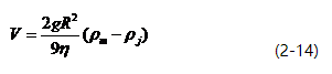
The upward velocity of inclusions can be calculated using Stokes’ law.
2.4 Raw Materials for Induction Furnace Smelting
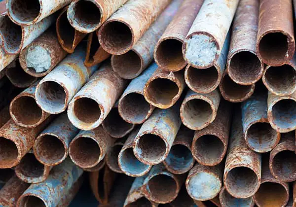
Requirements for raw materials: The chemical composition of the input materials should be accurate; the metal materials should be clean, dry, free from oil and rust; the block size is appropriate; all materials must be stored in a dry environment.
Types of raw materials: Steel materials: pig iron, industrial pure iron, scrap steel, return materials. Alloy materials: W, Mo, Nb and their iron alloys; Ni Cr, Co and their alloys; Si, Mn and their alloys; V, B and their alloys; Al, Ti and their alloys; rare earth metals and their alloys; special additives. Slag-making materials: lime, fluorite, clay brick fragments.
Ingredients calculation:
Based on the composition of the charge and the target composition of the smelted product, calculate the weight of each type of raw material to be added to the furnace.
Since the induction furnace mainly focuses on melting and heating processes, the requirements for ingredients calculation are more precise. Accurate calculation methods are required to calculate the recovery rate of alloying elements.
2.5 Induction Furnace Crucibles (Lesson 4)
2.5.1 Classification and Quality Requirements of Induction Furnace Crucibles
(1) Classification of crucibles:
Induction furnace crucibles can be classified into three types based on their materials: alkaline, acidic, and neutral. The most widely used binder is boric acid.
The role of boric acid in the production of acidic (silica sand) or alkaline (magnesia) crucibles includes:
a. Lowering the sintering temperature.
b. Promoting the formation of spinel.
c. Reducing the volume change rate of the crucible.
Crucibles can also be classified based on their manufacturing methods: precast crucibles, in-situ formed crucibles, and refractory brick-lined crucibles.
(2) Quality requirements for crucibles
The main requirements for refractory materials of crucibles include:
High refractoriness and high-temperature structural strength.
Good resistance to rapid heating/cooling.
Good resistance to slag corrosion.
As low thermal conductivity as possible.
Good insulation performance.
No pollution, harmlessness, low volatility, strong resistance to hydration, and low cost.
2.5.2 Preparation of Crucibles
(1) Particle size ratio:
Reasonable particle size ratio can achieve the best volume density to ensure that the crucible has the minimum porosity rate, usually around 20%. The coarse, medium, and fine range of sand particle sizes depend on the capacity of the furnace.
The particle size ratio of magnesia crucibles with the same capacity
There are two main methods for forming an induction furnace crucible: external forming and internal forming. According to the difference of binders, the internal forming method can be divided into wet forming and dry forming.
(3) Crucible Manufacturing
For externally formed crucibles, manufacturing refers to how the crucible is installed in the induction coil and how the furnace mouth is repaired. Here, we introduce the manufacturing process of internally formed crucibles. The preparation work before production includes sand preparation and mixing, cleaning and inspection of the induction coil, preparation of the crucible mold, and preparation of forming tools and equipment.
Before each crucible is made, the induction coil is checked for leaks, water seepage, insulation damage, and whether the fasteners between the induction coil and the turns are reliable and firm.
The mold mainly refers to the crucible core, which is used to control the shape and volume inside the crucible. The induction furnace crucible core is either welded with steel plates or made of graphite.
Graphite core Vibratory molding machine
(4) Crucible Sintering
Purpose: To improve the compactness, strength, and volume stability of the crucible.
Process: The contact surface of the sand material is heated to a high temperature to form a continuous sintering network through liquid phase bonding, which connects the entire sand material together into a whole.
Sintering methods: High-temperature sintering and low-temperature sintering.
A. High-temperature sintering of magnesia crucibles (divided into four stages)
Stage 1: Sintering temperature at 850℃, mainly for dehydration reaction of the sand material and decomposition of carbonate.
Stage 2: Sintering temperature between 850-1500℃, low-melting-point compounds begin to melt, sintering network begins to form, and the crucible volume shrinks significantly. The heating rate can be increased appropriately during this stage.
Stage 3: Sintering temperature between 1500-1700℃, magnesium olivine and magnesium-aluminum spinel start to melt, new compounds begin to form, sintering network is formed, and the crucible volume shrinks sharply, with significantly increased density and strength. The heating rate should be reduced during this stage.
Stage 4: Sintering temperature between 1700-1850℃, mainly to promote the continuous growth of forsterite, and obtain the ideal sintering layer thickness and sintering structure of the crucible cross-section.
B. Low-temperature sintering of magnesia crucibles (divided into three stages)
Stage 1: Temperature at 850℃, mainly for dehydration reaction and carbonate decomposition, with a slow heating rate.
Stage 2: Temperature between 850℃-1400℃, sintering network of low-melting-point compounds containing B2O3 forms rapidly, and the crucible strength increases.
Stage 3: Temperature between 850℃-1400℃, to continue to increase the sintering layer thickness of the preliminarily sintered crucible and achieve the ideal sintering structure.
2.6 Induction Furnace Melting Process
2.6.1 Melting Process
The scrap steel used for melting usually contains a certain amount of moisture and oil contamination. It is unsafe to directly add such furnace material into the furnace, especially in the case of an already formed molten pool, as it often leads to splashing. At the same time, it is also one of the main sources of oxygen in the product.
Therefore, some factories set up preheating or drying systems for scrap steel, using heating methods to remove the moisture and oil contamination attached to the scrap steel to ensure safe use and prevent hydrogen from being introduced. In addition, adding preheated scrap steel can shorten the melting time and reduce energy consumption.
(1) Charging
Raw material requirements:
a. The chemical composition of the charged material must be accurate;
b. The metal material should be clean, dry, oil-free, and have little rust;
c. Suitable size of the material blocks;
d. Dry storage.
Charging requirements:
The lower layer of the furnace material should be compact, and the upper layer should be loose to prevent bridging of the upper layer of furnace material during the melting process;
Before charging large materials, a layer of small and light material should be first laid on the bottom of the furnace;
Some alloys or steel materials with lower melting points than others should be charged first at the bottom of the furnace;
Materials with high melting points and are not easily oxidized should be charged in the upper part of the layered materials, i.e. the high-temperature zone;
The low-temperature zone at the top of the crucible should mainly be charged with steel materials;
Materials should be loosely charged to prevent bridging.
(2) Melting
The smelting of the furnace material is directly related to the change in gas content in the liquid metal and the recovery of alloy elements, while also affecting technical indicators such as smelting time, crucible life, and energy consumption. The melting period is an important stage in induction furnace smelting, with the following main tasks:
To rapidly melt the furnace material, desulfurize it, reduce the loss of alloy elements, and promptly add slag to prevent the metal melt from absorbing gas.
(3) Refining
The refining period is an important link in induction furnace smelting, completing tasks such as deoxidation, alloying and adjusting the composition and temperature of the steel liquid through refining.
Adjusting the composition of the slag to reduce the content of alloy elements in the slag.
Deoxidizing and alloying the steel liquid.
(4) Tapping and Casting
When the smelted steel or alloy meets the requirements for tapping, it can be tapped. For small-capacity furnaces, it can be directly cast. For larger capacity furnaces, it can be poured into a casting ladle first and then cast. Depending on the product requirements, it can be cast into ingots, castings, or consumable electrodes. The tapping process also requires selecting the casting method based on the quality and process flow of the product, such as whether to use vacuum or non-vacuum casting, and whether to use top pouring or bottom pouring.
Generally, electric heating alloys and high-temperature alloys need further refinement, so they are generally cast into consumable electrodes, while precision alloys are generally vacuum-cast. Vacuum casting can avoid secondary oxidation and re-absorption of the steel liquid during the casting process, and can effectively remove hydrogen and part of nitrogen, thus obtaining steel with fewer impurities and higher purity.
2.7 Composition Control in Induction Furnace Smelting (Lesson 5)
Chemical composition has a significant impact on the quality and performance of steel. For some types of steel, the chemical composition needs to be controlled within a more stringent range besides meeting the technical specifications, in order to meet the higher requirements for quality and performance. Chemical composition control runs through every furnace steelmaking process and is closely related to the loss of alloy elements, physicochemical properties, slag physicochemical state, steel liquid temperature, smelting method, etc.
(1) Main factors affecting the recovery rate of alloy elements
Physicochemical properties of the alloy elements themselves.
Smelting time. The longer the melting time, the greater the loss of C and Si, and the higher the loss of alloy elements when active elements are added and the time to tapping is longer.
Smelting temperature. With an increase in temperature, the free energy of the alloy elements in the steel decreases, which is conducive to the dissolution of the alloy elements. However, too high a temperature will exacerbate the loss of alloy elements.
Slag system. The physicochemical state of the slag has a significant impact on the recovery rate of alloy elements. Especially the viscosity and alkalinity of the slag have a greater influence. The higher the FeO and SiO2 content in the slag, the greater the loss of elements.
Volatile loss of elements. Attention should be paid to the volatile loss caused by oxides for W, Mo, and Mn.
Content of [O], [N], and [S] in the steel liquid. The higher the content of [O], [N], and [S] in the steel, the greater the loss of elements. The steel liquid should be fully deoxidized, desulfurized, and denitrified before adding alloy elements.
Timing, block size, and method of adding alloy elements. The earlier more active elements are added, the greater the loss. The recovery rate of alloy elements is higher when adding block-shaped alloy elements than when adding powdered ones. There is also a slight difference in the recovery rate between adding to the furnace or adding to the ladle.
(2) Methods to improve the recovery rate of alloy elements
1. Control method for low-loss elements: Alloy elements with a loss rate lower than 5% under normal smelting conditions are called low-loss elements, including Ni, Co, Mo, W, Cu, etc. Low-loss elements can generally be added together with the furnace charge, and electrolytic copper should be added at the end of melting due to its low melting point. The loss of Mo and W during their smelting is mainly due to the volatile loss of their oxides.
In addition, alloys containing tungsten cannot be smelted in a new crucible as it will lead to tungsten loss and non-conforming chemical composition due to the crucible absorbing tungsten. Tungsten-containing materials can also cause “bottoming phenomenon”, where a large amount of tungsten-containing material settles on the bottom of the crucible and cannot melt for a long time. To reduce the loss of W and Mo, sufficient melting and stirring should be ensured during smelting.
2. Control method for medium-loss elements: Medium-loss elements refer to elements with a loss rate between 5% and 20%, including Cr, V, Si, Mn, Nb, etc., and their addition depends on the situation in the furnace. Generally, Nb is added at the end of refining and stirred sufficiently. When smelting steel containing Cr, care should be taken to prevent chromium from oxidizing into the slag. If the chromium content is not high, it is best to add it after complete deoxidation. When adding Mn to eliminate the thermal embrittlement effect of FeS, Mn/S>8 should be controlled.
3. Control method for high-loss elements: Alloy elements such as Ti, Al, Re, Zr, etc. have a loss rate greater than 20% under normal smelting conditions and are high-loss elements. Generally, they should be added after final deoxidation. The addition method depends on the deoxidation system.
In addition, the method and timing of adding alloy elements should be comprehensively considered to control the recovery rate of alloy elements. For example, when smelting high-temperature alloys, Ti needs to be added. If Ti is added in the form of titanium sponge, even if it is added after final deoxidation, the recovery rate will only be around 70%. However, if titanium is made into Ni-Ti intermediate alloy and added, the recovery rate can reach more than 95%.
3. Vacuum Induction Melting (VIM)
3.1 Overview
Vacuum induction melting (VIM) is a method of melting materials under vacuum conditions by using electromagnetic induction to generate eddy currents for heating in metal conductors. The new vacuum induction degassing and pouring (VIDP) technology has the advantages of small melting volume, short vacuum pumping time and melting cycle, easy temperature and pressure control, easy recovery of volatile elements, accurate composition control, etc. Since its appearance in 1988, it has been listed as a key selection object for large-scale vacuum induction furnaces in developed countries.
3.1.1 Equipment of Vacuum Induction Furnace
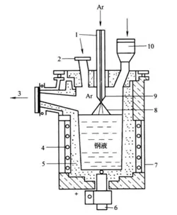
The vacuum induction furnace is an equipment used to produce superalloys. According to the operation mode, it can be divided into batch-type furnaces and semi-continuous operation furnaces. The vacuum induction furnace can be used for refining superalloys and also for casting special alloys. The supporting equipment of the vacuum induction furnace can be divided into four parts: power supply and electrical control, furnace body, vacuum system, and water cooling system, as shown in Figure 3-1 and 3-2.
The power supply of the vacuum induction furnace has the following requirements:
(1) The terminal potential of the inductor should be low. The operating voltage used by the vacuum induction furnace is lower than that of the medium-frequency induction furnace, usually below 750V, to prevent gas discharge under vacuum caused by too high voltage and damage to insulation, causing accidents.
(2) Prevent high-order harmonics from entering the load circuit. When using a thyristor frequency conversion circuit, high-order harmonics often enter the load circuit, causing the inductor to increase the voltage to the furnace shell and cause discharge. Therefore, it is necessary to add a medium-frequency isolation transformer at the output end of the power supply to intercept the entry of high-order harmonics.
(3) The current of the oscillation circuit should be large;
3.1.3 Structure of the Furnace Body of Vacuum Induction Furnace
The conventional structure of the vacuum induction furnace can be divided into a single-chamber vertical furnace and a two-chamber horizontal furnace according to the opening and closing form of the furnace body. The furnace body of the vacuum induction furnace mainly consists of a furnace shell, inductor, crucible, tilting mechanism, casting system, water cooling system, and power supply device. The structure of the furnace body includes two types: crucible rotating casting type and furnace body tilting casting type.
The furnace body of the vacuum induction furnace is equipped with accessories such as feeding, stirring, temperature measurement, and sampling devices. The greatest characteristic of the vacuum induction furnace is that the smelting and casting processes are carried out inside the furnace shell. The furnace shell is divided into a fixed furnace shell and a movable furnace shell. The furnace shell must withstand the strong pressure formed by the internal vacuum and have sufficient structural strength.
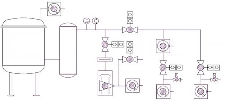
The furnace shell of small vacuum induction furnaces adopts a double-layer structure, with a non-magnetic stainless steel plate for the inner layer and an ordinary steel plate welded to the outer layer, and cooling water flowing in between. Large vacuum induction furnaces use a double-layer structure in some parts, with a single-layer steel plate cooled by water pipes on the outside. The contact surface between the movable part and the fixed part of the furnace shell must be sealed with vacuum rubber parts. The principle of the vacuum system is shown in Figure 3-3.
Figure 3-3 Vacuum System Principle Diagram
3.1.4 Characteristics of Vacuum Induction Furnace Melting
(1) Low gas content and high purity of the product;
(2) Precise control of the composition of the product;
(3) Strong adaptability to raw materials;
(4) It can be cast into ingots under vacuum conditions, as well as complex-shaped castings.
However, there are also some problems with vacuum induction furnace melting. During the melting process, the molten metal is in contact with the crucible refractory material for a long time, which inevitably causes contamination of the metal by the refractory material. Secondly, the solidification conditions of the molten metal and the general casting method are no different, so there are still defects such as looseness and segregation.
Table 3-1 Gas Content in SAE4340 Steel Produced by Different Melting Methods
Melting Methods
[O]/%
[H]/%
[N]/%
Charge material
0.0251
0.00018
0.0029
Electric arc furnace
0.0031
0.00017
0.0039
Non-vacuum induction furnace
0.0030
0.00010
0.0053
Vacuum induction furnace
0.0003
0.00001
0.0005
Table 3-2 Gas Content in SAE4340 Steel Produced by Different Melting Methods
Steel and alloys
Oxide inclusions, %
Non-vacuum induction furnace
Vacuum induction furnace
Cr20 Cr16Ni25W5AlTi2 Cr10Ni65Co10W5Mo5VAl4
0.034~0.044 0.025 0.013~0.044 0.012 0.006~0.010
0.006~0.010 0.006 0.003~0.010 0.0046 0.005~0.010
3.2 Theoretical Basis of Vacuum Melting
(1) Carbon Deoxidation Under Vacuum
The ability of carbon deoxidation under vacuum increases significantly with the increase of vacuum degree. At 1600℃, when the vacuum degree is 10-3 atm, the carbon deoxidation ability has exceeded that of aluminum; When the system vacuum degree is 10-5 atm, the carbon deoxidation ability is 105 times that under atmospheric conditions. Carbon deoxidation is mainly utilized under vacuum.
(2) Gas Dissolution in Steel and Its Influencing Factors
The solubility of diatomic gas molecules in molten metal is proportional to the square root of the gas pressure in the atmosphere. Therefore, the higher the vacuum degree, the lower the solubility of gas in the metal.
At 1600℃ and PH2=100Kpa, the effect of alloy elements on the solubility of nitrogen in molten iron, as well as the effect on the solubility of hydrogen in molten iron at 1600℃ and PN2=100Kpa, should be taken into account.
3.3 Process of Vacuum Induction Furnace Smelting
The entire cycle of vacuum induction furnace smelting can be divided into several main stages, including charging, melting, refining, alloying and deoxidation, pouring, etc.
3.3.1 Charging
(1) Raw Material Requirements
The charge material used in the vacuum induction furnace is generally clean raw materials that have been surface derusted and degreased, with most of the alloy elements added in the form of pure metal. Wet charge materials should not be used during charging to avoid affecting the quality of the finished product and causing splashing during melting. During charging, the upper part of the charge material should be loose while the lower part should be tight to prevent “bridging” caused by the upper charge material getting stuck or welded during the melting process. A layer of small lightweight material should be laid on the bottom of the crucible before charging large-sized materials. High-melting, difficult-to-oxidize charge materials should be loaded in the high-temperature zone at the middle and lower parts of the crucible. A few active elements such as Al, Ti, Mn, B, and rare earths can be loaded into separate feeders.
(2) Charging Requirements
I. The lower layer of the charge material should be compact, while the upper layer should be loose to prevent bridging of the upper layer of charge material during the melting process; a layer of small lightweight material should be laid on the bottom of the crucible before charging large-sized materials.
II. High-melting, difficult-to-oxidize charge materials should be loaded in the high-temperature zone at the middle and lower parts of the crucible.
III. Easily oxidizable charge materials should be added under good conditions for metal deoxidation.
IV. To reduce the loss of volatile elements, alloy can be added to the metal melt in the form of an alloy or inert gas can be introduced into the melting chamber to maintain a certain furnace pressure.
3.3.2 Melting Phase
For a vacuum furnace that operates on an intermittent basis, after the charge material has been loaded, the vacuum chamber is closed and the vacuum is pumped out. When the pressure in the vacuum chamber reaches 0.67 Pa (5×10⁻³ mmHg), the power can be turned on to heat the charge material. For continuous production furnaces with charge materials loaded under vacuum conditions, power can be supplied to enter the melting phase as soon as the charging is completed. Considering the degassing effect of the charge material during melting, the maximum power input is not required during the initial melting stage. Instead, the power should be gradually increased according to the degassing situation of the charge material to avoid excessive degassing causing splashing. When violent boiling or splashing occurs, the input power can be reduced or the furnace pressure can be slightly increased to control it. The sign of a clear molten pool is that the surface of the molten pool is calm, with no bubbles escaping. Then it can proceed to the refining phase.
3.3.3 Refining Phase
The main tasks of the refining phase are to improve the purity of the liquid metal and to carry out alloying. At the same time, the temperature of the melt and the alloying need to be adjusted. The goal of the refining phase is to reduce gas content, remove harmful impurities, and make the steel composition qualified. The temperature of the refining phase should be controlled above 100 ℃ of the melting point of the smelted metal. The vacuum degree for large vacuum induction furnaces is usually between 15-150Pa; for small furnaces, it is between 0.1-1Pa. The refining time is 15-25 minutes for a 200 kg furnace and 60-100 minutes for around one ton.
3.3.4 Alloying
Alloying refers to the adjustment of the composition, which is done under good deoxidation and degassing conditions by adding alloy elements. The type and quantity of elements added are determined by the requirements for the alloy properties, and the order and conditions of addition are determined by the affinity and volatility of the alloy elements with oxygen. After adding each element, the power should be increased and stirred for a certain amount of time to accelerate melting and ensure even distribution.
3.3.5 Steel Casting and Pouring
After the alloying phase, when the metal liquid in the crucible reaches the target composition and temperature, and the straightness of the vacuum chamber meets the technical requirements, the steel can be cast. When pouring into the insulation cap, the vacuum is broken immediately and the heating agent and insulation agent are added to avoid shrinkage porosity entering the ingot body. For high-temperature alloys with complex compositions, they should be left in the vacuum for 15-20 minutes after casting before breaking the vacuum. For large continuous vacuum induction furnaces, the ingots can be allowed to cool under vacuum.
3.4 The volatility of elements and composition control
All metals (including some non-metals) have an equilibrium vapor pressure Poi, which depends on the physical properties of the metal, the gaseous state form (single atom, diatomic or multi-atomic molecule), and the temperature. The relationship between the vapor pressure Po of substance i and temperature is as follows: (P0 is standard pressure and needs no modification)
lg(Poi/133.3)=AT-1+BlgT+TC×10-3+D (3-1)
where the unit of Poi is Pa. The parameters A, B, C, D and other relevant physical properties of elements related to steel metallurgy are listed in Table 3-5. The higher the vapor pressure of an element, the more likely it is to volatilize during vacuum smelting. According to the data in Table 3-5, the decreasing order of Poi for each element at 1873K can be calculated as follows: Zn, Mg, Ca, Sb, Bi, Pb, Mn, Al, Sn, Cu, Cr, Fe, Co, Ni, Y, Ce, Sl, La, Ti, V, B, Zr, Mo, Nb, W, Ta.
The vapor pressure Pi of component i in an alloy or crude metal is not equal to the vapor pressure Poi of pure substance i because the concentration of i in the alloy is necessarily lower than that in the pure substance. In addition, the interaction between the molecules of i and the other component elements in the alloy is not equal to that among the i molecules. The formula for calculating Pi is:
Pi= ai .Poi,= r i .N i .Poi (3-2)
In the formula:
ai: activity of component i in the alloy
ri: activity coefficient of i
Ni: molar fractional concentration of i
In ferrous alloys, alloying elements can be divided into three categories: non-volatile, easily volatile, and impurity elements that can be removed by volatilization. Non-volatile elements include Ti, V, B, Zr, Mc (Hf), Nb, Ta, and W. Easily volatile elements include Mn, Al, Cr, Fe, Co, Ni, Cu, Ca, and Mg. Under vacuum smelting conditions, these elements will volatilize to varying degrees. Steel and alloys contain some trace metal elements that have a significant impact on the performance of steel and alloys. They are difficult to remove by conventional chemical methods. If these elements have high vapor pressure, they can be removed by volatilization during vacuum smelting. These metal elements include Sn, Pb, Bi, Sb, and Zn.
Trace elements such as magnesium, zirconium, boron, etc., are used for microalloying; trace impurities such as Pb, Bi, As, Sb, and Sn are harmful to steel and alloys. Pure magnesium has high vapor pressure at melting temperatures, low density, and strong affinity for oxygen, which makes magnesium alloying difficult.
During vacuum smelting, magnesium is added in the form of binary or ternary alloys during the later stage of melting. To improve the recovery rate of magnesium, the following points should be noted when adding magnesium:
(1) The temperature of the molten steel should be about 20°C lower than the tapping temperature before adding magnesium.
(2) The holding time should be controlled after adding magnesium, generally added within 1-5 minutes before tapping.
(3) Argon gas should be introduced into the furnace before adding magnesium to ensure high recovery rate of magnesium.
Trace harmful elements in steel and alloys are usually low-melting impurities accumulated from repeated use of scrap or contained in some iron ore. Vacuum refining is the most effective method for removing these harmful impurity elements because they generally have high vapor pressure. Due to different vapor pressures and the varying influence of other component elements, the volatilization rates of these elements differ greatly.
3.5 Interaction between Metal Melts and Refractory Materials under Vacuum
With the continuous development of induction furnace technology, the capacity of coreless induction furnaces has been increasing, and the vacuum and traditional induction furnaces that have been put into production have reached 60t and 40t, respectively. In the 1960s, the United States successively manufactured VIM (Vacuum Induction Melting Furnace) furnaces with capacities of 15t, 30t, and even 60t. The increase in electric furnace capacity also correspondingly increases the demand for high-purity refractory materials with special physical properties.
The operating conditions for refractory materials used in vacuum smelting are generally more stringent than those used in conventional smelting. This is because many refractory materials decompose according to their composition and react with the molten metal under vacuum conditions. On the one hand, this contaminates the molten metal, and on the other hand, it increases the corrosion of the refractory material. This is particularly evident in refractory materials containing large amounts of silica and iron oxide.
The shrinkage cracks that occur in refractory materials used in vacuum smelting are more severe than those in conventional smelting, especially in high-capacity (>2.5t) coreless induction furnaces. Therefore, refractory materials for large-scale induction furnaces should have the following characteristics:
(1) Irreversible expansion, no shrinkage cracks will occur;
(2) High purity;
(3) Good stability in a vacuum environment;
(4) Able to withstand the erosion of molten metal and slag.
Refractory materials with these characteristics include high-purity magnesia-alumina-spinel and alumina. In recent years, the batching of these refractory materials, as well as the corresponding repair materials and binders, have developed significantly.
Magnesia and alumina react to form high-purity magnesia-alumina-spinel with low density. The lining made of magnesia-alumina-spinel can be used at a temperature of 1647℃, and after being cooled to room temperature or filled with cold materials, it can be heated and used at 1647℃ without cracking after dozens of cycles. According to relevant reports, the lining of a nominal capacity 6t induction furnace is made by ramming 95% alumina. When producing 300 and 400 series stainless steel, the furnace lining can be used continuously for 150 furnaces without any treatment.
3.6 Application of New Technologies in Induction Furnace Smelting
In the nearly 80 years since the induction furnace was invented, there have been significant advancements in both equipment and processes. As a result, measures have been adopted to improve induction furnace smelting in terms of production volume, productivity, product quality, and product range. These measures include magnesium treatment of alloys, low oxygen potential dephosphorization, argon blowing, powder injection, hydrogen-oxygen mixed gas decarburization, and hydrogen refining of liquid steel.
3.6.1 Magnesium Treatment of Alloys
High-temperature nickel or iron-based alloys, as well as precision alloys containing high levels of alloying elements, some of which are more reactive than others, such as aluminum and titanium, cannot guarantee satisfactory properties such as thermal plasticity, weldability, high-temperature strength, and creep resistance even when smelted under vacuum conditions. Therefore, a certain amount of magnesium is added at the end of refinement. The residual magnesium in the metal can significantly improve these properties.
The specific physicochemical properties of magnesium determine that it is difficult to control the addition method and recovery rate during the magnesium addition process. To address this issue, magnesium alloys such as Ni-Mg and Ni-Mg-Me are used to reduce the vapor pressure of magnesium and increase its melting point and boiling point. The operation process for magnesium treatment is as follows:
(1) After the refining period is over, if B and Ce need to be added, adjust the temperature of the melt so that it is 20℃ lower than the tapping temperature after adding B and Ce;
(2) Fill the vacuum chamber with high-purity argon gas to a pressure of 13-27kPa;
(3) Add magnesium in the form of a block-shaped intermediate alloy containing magnesium to the metal melt;
(4) Immediately stir vigorously after adding magnesium, and avoid stirring for too long to reduce the loss of magnesium. The steel should be tapped within 1-5 minutes after adding magnesium.
3.6.2 Low Oxygen Potential Dephosphorization
When melting alloy steel, especially when using return materials as furnace charge, it is necessary to control the oxygen potential of the furnace gas and slag during the melting and refining process to reduce the loss of alloying elements. Therefore, oxidizing methods cannot be used to dephosphorize during the smelting process. When low-phosphorus steel is required, only raw materials with a phosphorus content lower than the specification requirements can be used, which increases production costs. To solve the problem of dephosphorization during the smelting of high-alloy steel return materials, the theory and practice of low oxygen potential dephosphorization have been proposed in recent years and have also been applied in induction furnace smelting.
Calcium and phosphorus in the steel can react under the conditions of sufficient deoxidation and desulfurization of the steel liquid as follows:
3Ca+2[P] = Ca3P2 (3-3)
The product formed is calcium phosphide. The calcium involved in the reaction can be metallic calcium, calcium alloys (such as silicon-calcium alloys), or calcium compounds (such as CaC2). Due to the low melting point (839℃), high vapor pressure (P = 1.775×10⁵ Pa at 1600℃), and low solubility in the steel liquid of metallic calcium, it quickly evaporates into vapor form after being added to the steel liquid and floats up and out in the form of bubbles. During the floating process, calcium vapor can react with the phosphorus in the steel to generate Ca3P2, but the utilization rate of calcium is very low. Calcium alloys or compounds are commonly used instead.
The Ca3P2 generated by the reaction is an insoluble compound in the steel liquid, with a melting point of 1320℃ and a density of 3.3 g/cm³. It will float up in liquid form and enter the slag at the steelmaking temperature. However, calcium phosphide is not stable under the conditions of steelmaking and is a strong reducing agent. When the oxygen potential of the furnace atmosphere is high and there are easily reducible oxides in the slag, the following reaction will occur:
(Ca3P2) + 4O2 = 3 (CaO)+ (P2O5) ; (3-4)
y (Ca3P2) + 8 (MexOy) = 3y (CaO) + y (P2O5) + 8x [Me] (3-5)
When there is water vapor in the furnace gas:
(Ca3P2)十3H2O= 3 (CaO) + 2PH3 ↑; (3-6)
PH3 is a gas that will take away phosphorus with furnace gas when there is water vapor, but this gas is toxic, and precautions should be taken to prevent this reaction from occurring during operation. Special measures should be taken to ensure safety when processing furnace slag containing Ca3P2. When the slag has a high alkalinity, CaO.P2O5 with higher stability will be produced.
3 (CaO) + (P2 O5)= (3 CaO.P2 O5) (3-7)
However, both silicon calcium and CaC2 used for low oxygen potential dephosphorization have strong reducing properties. Therefore, when there is an excess of silicon calcium or CaC2 in the slag, calcium phosphate will decompose and P2O5 will be reduced, causing phosphorus to return to the steel and reducing the efficiency of dephosphorization under low oxygen potential.
In actual operation, maintaining low oxygen potential of the steel and timely removing phosphorus-containing slag are the keys to improve the efficiency of calcium dephosphorization. When adding calcium, precautions should be taken to prevent violent gasification of calcium, which can cause splashing. When CaC2 is used as a dephosphorizing agent, it is required to cover the crucible and fill it with a reducing or inert gas to avoid oxidation of CaC2 in the slag. In the smelting of Cr12MoV mold steel, the amount of powder used is 10-15 kg/t, and the dephosphorization rate is about 0.005%. After the powder spraying ends, remove the slag immediately and make new slag.
3.6.3 Argon Blowing
Argon blowing in the ladle is already a mature technology in the smelting of ordinary steel and low-alloy steel. It relies on the upwelling of argon bubbles to stir the molten steel, promote the carbon-oxygen reaction, adhere to and promote the collision, growth, and upwelling of inclusions at the surface of the bubble, and can also de-gas under certain conditions.
When the purity of argon is high and very dry, blowing argon can remove some gases, especially hydrogen. When the argon blowing time is about 20 minutes, the dehydrogenation rate can reach about 50%. Harmful trace elements with high vapor pressure at the steelmaking temperature, such as lead and arsenic, can also be removed to different degrees through argon blowing. According to reports, blowing argon for 20 minutes can remove 70-80% of lead in steel, but the removal rate of arsenic is only 10%.
3.6.4 Powder Injection
Powder injection metallurgy is a new technology developed recently to refine molten steel. Ladle powder injection has been widely used in conventional steelmaking production, and different powder agents can be used to complete metallurgical tasks such as dephosphorization, desulfurization, deoxidation, controlling the morphology of inclusions, alloying or carbon addition. Powder injection technology is essentially a technology that adds solid materials to molten steel.
Since the powder is transported by carrier gas, the carrier gas that enters at the same time as the powder will cause agitation of the melt, thereby improving the kinetic conditions of metallurgical reactions. Therefore, powder injection is more effective than traditional solid material addition technology. Of course, this adding technique can also be used for induction furnace melting.
In the induction furnace melting, dephosphorizing agent (calcium alloy or calcium compound) or desulfurizing agent can be blown. The commonly used desulfurizing agent is mainly lime-based powder (w(CaO) 60-80%, w(CaF2) 20-40%). This desulfurizing agent is easy to obtain, cheap, and has no effect on the composition control of the molten steel, and the desulfurization rate is about 30-50%.
Another widely used desulfurizing agent is Ca-Si-CaF2 (where w(CaF2) is 20-30%), most of the silicon in this desulfurizing agent will be absorbed by the molten steel, which can increase the silicon content, and the desulfurization rate can reach 40-80%. For steels that do not require carbon addition, good desulfurization effect can also be achieved by adding a certain proportion of CaC2 to lime-based desulfurizing agents.
Bottled argon gas is commonly used as the carrier gas for powder injection. Nitrogen can also be used for steel grades that do not require nitrogen content, which can reduce costs. The working pressure is generally 0.2-0.3 MPa. Under the premise of ensuring uniform delivery of powder, the working pressure should be minimized as much as possible. A steel pipe with external refractory material is used as the injection gun and is inserted to a depth equal to the melt pool depth minus the penetration depth.
3.6.5 Argon-oxygen Decarburization
The United Carbide Corporation of the United States studied the equilibrium relationship of the Fe-Cr-C-O quaternary system in an induction furnace and found that there is a corresponding relationship between the carbon and chromium content dissolved in iron and the partial pressure of carbon monoxide (PCO) in the gas phase with temperature. Under certain chromium content, the equilibrium carbon content decreases with the increase of temperature or the decrease of PCO in the gas phase. Therefore, as long as the PCO in contact with the molten steel can be reduced, the carbon in the molten steel can be reduced to a low level at a not too high temperature, and chromium will not suffer too much oxidation loss.
Based on this, the AOD method of diluting PCO partial pressure with argon was proposed, that is, argon-oxygen mixed gas blowing decarburization. This method overcomes the disadvantages of high temperature, large chromium loss, increased carbon content of graphite electrodes, low furnace lining life, and large consumption of low-carbon chromium iron or metallic chromium when smelting chromium stainless steel by oxygen blowing in arc furnaces, and has been rapidly developed and widely used.
Since the AOD method was developed on the induction furnace, the argon-oxygen decarburization method should also be applicable to induction furnace melting. When smelting chromium or nickel-chromium stainless steel in an induction furnace, argon-oxygen mixed gas can be blown to remove carbon from the steel.
4. Electric Slag Remelting
4.1 Electric Slag Remelting Equipment and Basic Principles
Electric slag remelting (ESR) is a widely used secondary refining method for the production of high-quality steel and alloys. This process utilizes the heat generated from the electrical resistance of the slag to remelt the consumable electrode in a water-cooled crystallizer. Compared to vacuum consumable electrode arc melting, ESR does not require a vacuum system and often uses an AC power source, making it a simpler and more easily operable process with compact and high-quality ingots.
4.1.1 Electric Slag Remelting Equipment
Compared to vacuum consumable electrode arc melting, electric slag remelting equipment is relatively simple and consists of several components, including a power transformer and short circuiting device, a consumable electrode lifting system, a crystallizer with a bottom water tank, a measurement and control system, and a supply and dust removal system. Here, we will only introduce the power transformer, crystallizer, bottom water tank, and various types of electric slag furnaces.
(1) Power Transformer
The unique feature of the electric slag remelting process is its use of high current and low voltage AC or DC power sources. Therefore, it is necessary to choose a suitable transformer to convert the high voltage input into low voltage (40-100V) output that matches the capacity of the electric slag furnace.
(2) Crystallizer
The crystallizer is the most important component of the electric slag furnace. During the ESR process, the consumable electrode melts inside the crystallizer, and the liquid metal is forcibly cooled and crystallized to form a metal ingot or casting. The crystallizer is both the melting chamber of the furnace and the mold for metal solidification. It has a complex shape and structure, and there are three main types: ingot-type crystallizer, sliding-type crystallizer, and combined-type crystallizer (as shown in Figure 4-4).
4-5 Sliding Type Crystallizer; 5-Crystallizer; 6-Bottom Water Box
6-7 Detachable Type; 8-Mobile Type
Figure 4-3 Single-phase Fixed Electric Arc Furnace
Figure 4-4 Single-phase Bipolar Series Electric Arc Furnace
Figure 4-5 Three-phase Electric Arc Furnace
4.1.2 Basic Principles of Electric Arc Remelting
(1) Basic principle of remelting
During the electric arc remelting process, the current passes through the consumable electrode, slag, metal melt pool, solidified metal ingot and bottom water box, and finally flows through the short circuit, transformer, etc., forming a loop (see Figure 4-6). For a bipolar series electric arc furnace, the current flows from one of the consumable electrodes through the slag (a small part of the current also flows through the metal melt pool, and then back to the slag), then passes through the other consumable electrode, and finally returns to the transformer to form a loop.
The process of electric arc remelting includes the formation of a slag pool, melting of the consumable electrode, solidification of the remelted metal, and repair and shrinkage of the remelted ingot, all of which are performed in a continuous working procedure.
When the current passes through the slag, due to the high resistance of the slag, strong Joule heating is generated in the slag pool. The heat Q precipitated in the slag pool per unit time is expressed as follows:
Q = I2R (4-1)
Where: Q – Joule heat generated per unit time, J/s;
I – current intensity of the electrically conductive slag, A;
R – resistance of the slag pool at the melting temperature, Ω.
As the consumable electrode is inserted into the slag layer, the insertion portion of the consumable electrode is heated by the high temperature of the slag and exceeds its own melting point. As a result, the surface layer of the electrode tip begins to melt, forming a thin layer of liquid metal, which attaches to the upper part of the electrode tip. At the same time, under the action of gravity g, electromagnetic force R, and the scouring force of slag pool movement F, it flows downward along the surface of the electrode end and concentrates in the central part of the electrode to form molten droplets. Gravity causes the molten droplets to fall downward, while the interfacial tension δ between the slag and the molten droplets prevents the molten droplets from falling (see Figure 4-7).
The melting of the consumable electrode and the transition of metal droplets during the remelting process can be divided into the following three stages:
1) Liquid metal film is formed at the end of the consumable electrode;
2) Aggregated into molten droplets and transitioned to the metal melt pool through the slag layer;
3) Entered the surface of the metal melt pool.
Figure 4-6 Basic Principle Diagram of Electric Arc Remelting
Figure 4-7 Schematic diagram of force on molten metal droplets
7 – bottom water box; 8 – transformer; 9 – short circuit; 10 – holder; 11 – consumable electrode
4.2 Advantages of Electric Arc Remelting
Compared with general smelting methods, the electric arc remelting process differs in that the remelting process, including the formation of slag pool, melting of consumable electrode, solidification of remelted metal, and repair and shrinkage of remelted ingot, are all performed in a continuous working procedure. Therefore, it has a series of advantages.
(1) The remelted metal can be effectively refined by the slag.
(2) Improve the crystallization conditions of the metal ingot and increase the yield of the metal.
(3) The equipment is simple, the production cost is low, and the operation is easy to master.
(4) There are many product varieties and wide application range.
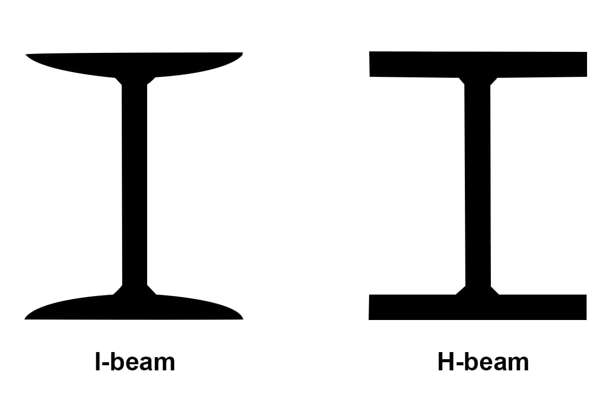
(5) Electric arc remelting also has a major advantage, which can produce metal ingots with different cross-sections, such as round, square, rectangular, and metal ingots with large width-to-length ratios. It can also produce hollow pipes and castings with different shapes, such as hollow tube blanks, rolling mill billets, high-pressure vessels, large high-pressure valves, and crankshafts.
However, there are some drawbacks to electric arc remelting, such as low productivity, high electricity consumption, poor degassing effect, difficulty in accurately controlling the chemical composition when remelting steels with high Ti and Al elements, and higher production costs compared to general smelting methods.
4.3 Selection of Raw Materials, Slag System, and Process Parameters for Electric Arc Remelting
4.3.1 Raw Materials for Electric Arc Remelting
(1) Consumable Electrode
The consumable electrode used in electric arc remelting is generally a metal ingot smelted by an arc furnace or induction furnace, which is made into a metal rod after rolling or forging. Its cross-section can be circular, square, or rectangular, and its variety should be the same as that of the finished product after remelting. In order to avoid the oxidation and burning of easily oxidizable elements during the remelting process, it is required that the surface of the consumable electrode should be free of rust and oxide skin, especially when remelting steels and alloys containing Al, Ti, B, and other elements. During the remelting process, except for easily oxidizable elements (such as Ti, Al, etc.) that may be burned, other elements basically do not change. For these easily oxidizable elements, they should be controlled within a certain range when preparing the consumable electrode according to the burning amount during the remelting process. To avoid the eccentricity of the consumable electrode during the remelting process, it is required to be as straight as possible, with a bend radius not exceeding 6mm per meter.
(2) Ingot protection plate
At the beginning of remelting, in order to prevent the bottom water box from being burned through, a metal plate called an ingot protection plate can be placed under the crystallizer and above the bottom water box. The ingot protection plate is made of the same material as the consumable electrode. The surface of the ingot protection plate should not have oxide skin and rust, and it should be very flat, so as to ensure close contact with the surface of the bottom water box and achieve good conductive effect. The thickness of the ingot protection plate is generally selected as 12-18mm.
(3) Ignition slag material
As we all know, when electric arc remelting, the molten slag has a certain conductivity. When the slag material is solid, its conductivity is poor and cannot be used to conduct heat and establish a slag pool directly. If solid slag is used as the ignition slag material, a slag with sufficient conductivity in the solid state must be found. In practice, it has been found that when the solid slag contains a certain amount of TiO2, it can meet this requirement. Therefore, for a considerable period of time, solid slag containing TiO2 was used as the ignition slag material for electric arc remelting.
(4) Remelting slag material
The slag plays an important role in the electric arc remelting process. The commonly used slag systems are mainly composed of fluorite (CaF2), alumina (Al2O3), lime (CaO), and magnesia (MgO), etc. (see Table 4-1).
4.3.2 Selection of Process Parameters for Electric Arc Remelting
(1) Size of electric slag ingot
The relationship between the weight and size of the ingot satisfies Equation 4-2.
Weight of G-spindle, t; diameter of D-spindle, cm; height of h-spindle, cm; specific gravity of γ-melted metal, g/cm3.
Table 4-1: Common slag systems and their densities in liquid state, as well as melting points.
Composition of slag system in percentage (%).
Density of slag in grams per cubic centimeter (g/cm3)
Melting point in degrees Celsius (℃).
CaF2
CaO
A12O3
1450℃
1650℃
–
100
–
–
2.52
2.42
–
90
10
–
2.57
–
1390~1410
80
20
–
2.63
2.50
1200~1220
70
30
–
2.66
–
–
60
40
–
2.69
–
–
70
–
30
2.88
2.80
1320~1340
80
10
10
2.69
–
60
20
20
2.90
–
1240~1260
(2) Dimensions of crystallizer and self-consuming electrode
The diameter D of the crystallizer is determined by the following formula:
where D is the average diameter of the crystallizer in millimeters (mm); D_pro is the diameter of the product in millimeters (mm); M is the machining allowance for the blank (for ingots, M=0; for castings, M=10-15mm); δ% is the shrinkage of the ingot (generally 3±0.5%).
The height H of the crystallizer is determined by the following formula:
If D is greater than 300mm, then H should be taken as the lower limit.
The diameter of the self-consuming electrode d_pole can be determined by the following empirical formula, which depends on the diameter D of the crystallizer:
where K is the filling ratio, usually chosen from 0.4-0.6; d_pole is the diameter of the self-consuming electrode in millimeters (mm); D is the diameter of the crystallizer in millimeters (mm).
Currently, different countries around the world choose different filling ratios K based on their actual situations. A larger K value is better for reducing energy consumption, improving productivity, and improving ingot quality, while ensuring the quality of the remelted metal and safe operation. The diameter of the self-consuming electrode cannot be too large, as this will affect the safety of the operation.
The length L_pole of the self-consuming electrode can be calculated using the following formula:
where G is the mass of the metal ingot in tons (t); n is the number of self-consuming electrodes required to produce one metal ingot; γ is the density of the remelted metal, which is generally taken as 7.9g/cm3 for ordinary steel; Z is the electrode density, which is taken as 0.95 for cast electrodes and approximately equal to 1 for forged and rolled electrodes; ΔL is the tailing length of the electrode, which should be determined based on the electrode clamping method, generally taken as (2-3)d.
(3) Smelting voltage
The smelting voltage refers to the sum of the working voltage and the voltage drop in the line during remelting. The working voltage is close to the slag layer voltage and more accurately represents the actual voltage. It determines the depth of immersion of the self-consuming electrode, affects the formation of satisfactory ingot axial crystals and surface quality, and is related to the degree of oxidation of elements. Properly increasing the furnace mouth voltage can refine the molten droplets, increase the slag temperature, and promote ingot axial crystal growth. Generally, for slag systems with good conductivity and low resistance, a lower working voltage should be selected. When smelting alloys containing easily oxidizable elements such as Al, Ti, and steels or alloys prone to segregation, a lower working voltage should also be selected. The working voltage can be selected using the following empirical formula:
where U is the working voltage in volts (V); D is the diameter of the crystallizer in centimeters (cm); B is a constant, taken as 27-37V.
(4) Smelting current
Smelting current is an important parameter that has a significant impact on product quality and economic and technical indicators. Increasing the smelting current leads to greater immersion depth of the self-consuming electrode, which is detrimental to the axial crystals of the ingot. The smelting current is mainly determined by the sectional area of the self-consuming electrode and the current density.
I = A*J (4-8)
where A is the sectional area of the self-consuming electrode in square millimeters (mm2); J is the current density in amperes per square millimeter (A/mm2).
The current density J can be selected using the following empirical formula:
where d is the diameter of the self-consuming electrode in millimeters (mm).
(5) Input power
The input power is used to check whether the voltage and current values are appropriate or to provide a basis for selecting transformers for equipment. The input power is determined based on the unit slag pool volume input power. If D =400-800mm, the effective input power is 0.15-0.30KW/cm2; if D =200-400mm, the effective input power is 0.30-0.60KW/cm2; if D < 200mm, the effective input power is greater than 0.60KW/cm2.
(6) Amount of slag and depth of slag pool
The amount of slag is determined using the following formula, with commonly used slag systems and densities shown in Table 4-3:
where G is the weight of slag in kilograms (kg); D is the diameter of the crystallizer in centimeters (cm); h is the depth of the slag pool in centimeters (cm); γ is the density of the remelted metal in kilograms per cubic centimeter (kg/cm3).
The depth of the slag pool can be determined using the following empirical formula:
Take the upper limit when D ≤250mm, and take the lower limit when D >350mm. According to literature, the amount of slag for single-phase electric furnaces in China is 30-40kg/t, the amount of slag for three-phase electric furnaces in China is 60-70kg/t, and the amount of slag abroad is 3-5% of the weight of the ingot.
(7) Cooling water temperature
In order to promote ingot crystallization and prevent accidents, a higher cooling intensity is required for the crystallizer and bottom water tank. The cooling water pressure is usually required to be 1.5-2.0kg/mm2, and the outlet water temperature of the crystallizer should be controlled at 40-60℃.
4.4 Metallurgical characteristics of electric slag remelting (Lesson 11)
The process of electric slag remelting includes the formation of the slag pool, melting of the self-consuming electrode, solidification of the remelted metal, and the supplementing and shrinking of the remelted ingot. These processes are carried out in a continuous working procedure.
4.4.1 Formation of the electric slag remelting slag pool
(1) Function of slag
Heat source for the remelting process.
Effective refinement.
Protecting the remelted metal with the slag layer.
In addition, during the solidification process of the remelted metal, a thin and uniform slag shell is formed on the surface of the ingot, protecting the crystallizer from direct contact with high-temperature slag and making the surface of the ingot smooth and easy to demold.
(2) Properties of slag
A certain electrical conductivity.
Low viscosity and melting point.
Low vapor pressure.
Suitable interfacial tension of slag.
Moderate density of slag.
Suitable permeability of slag.
(3) Selection of slag system
The slag should be selected based on the analysis of the physical properties of the slag mentioned above. Commonly used slag systems are shown in Table 4-1.
The melting point of the slag system should be 100-200℃ lower than that of the remelted metal, and the viscosity of the slag should also be small. This will enable good flowability of the slag during the remelting process, which is beneficial for desulfurization and removal of non-metallic inclusions. It will also help to form a thin and uniform slag shell on the surface of the ingot, facilitating ingot solidification and obtaining a smooth surface.
The CaF2-CaO slag system has significant desulfurization ability, and the desulfurization ability increases with the increase of the basicity of the slag. When remelting sulfur-containing free-cutting steel, an acidic slag operation with R<1 is required to ensure the sulfur content in the steel.
During electric slag remelting, it is better to have fewer unstable oxides (FeO, MnO, etc.) and oxides of variable valence metals (MexOy) in the slag to prevent the increase of [O] content in the metal and the burning loss of elements. When smelting steels and alloys containing elements such as Al, Ti, and B, the slag should not contain SiO2.
Since alkali metal oxides such as Na2O and K2O have low melting points and are easy to volatilize, the slag should not contain these oxides.
(4) Establishment of slag pool
At the beginning of the remelting process, the remelted slag pool should be quickly established to ensure the smooth progress of the electric slag remelting process. There are two methods to establish the slag pool: the visible arc method and the invisible arc method, with the latter being mainly used in current production. In the invisible arc method, the solid conductive slag ignition method and the liquid slag method are mainly used.
4.4.2 Melting of self-consuming electrode
During the dripping process of the remelted metal droplets, the transition characteristics mainly manifest as the frequency of droplet dripping and the size of the droplet diameter, which have a considerable influence on the refinement of the metal.
Firstly, the composition of the slag has a significant effect on the droplet size. When using an ЭП65 steel self-consuming electrode with a diameter of d_pole=200mm, a crystallizer diameter of D_pro=425mm, and a CaF2-Al2O3 slag system with different amounts of added Al2O3 for remelting, the change in droplet quality is listed in Table 4-2.
Table 4-2 Changes in Droplet Fusion.
Al2O3 Content in CaF2-Al2O3 Slag, /%.
Voltage, /V
Current, /A
Droplet Dropping Frequency, drops/s
Average Droplet Mass, /g
1
61
7500
5.07
6.90
5
61
7500
6.53
7.50
15
61
7500
7.01
7.95
30
61
7500
7.06
11.70
Moreover, there is a certain relationship between the depth of the slag pool and the droplet dropping frequency and size. When a small cross-sectional self-consumption electrode is used, an increase in the depth of the slag pool leads to a decrease in the droplet dropping frequency and an increase in the droplet diameter (see Table 4-3).
Table 4-3 Relationship between Slag Pool Depth, Droplet Dropping Frequency, and Droplet Diameter.
Slag Pool Depth, /mm
30
50
70
Droplet Dropping Frequency, drops/s
21.5
14.8
11.5
Average Droplet Mass, /g
0.11
0.16
0.21
Average Droplet Diameter, /mm
3.12
3.54
3.86
Note: The electrode lifting speed is 1.55m/h; voltage is 45V.
The stability of the remelting process in electroslag production is closely related to the descending speed of the self-consumption electrode. When the electrode descends slowly, the electroslag process transitions to an arc process. At this time, the end of the electrode is flat, and droplets are usually distributed on the edge of the electrode face (see Figure 4-18a). At the moment the droplets fall, arcing can be observed, and the electroslag process is unstable. When the descending speed of the electrode is increased, a conical protrusion appears at the end of the electrode (see Figure 4-18b), and droplets form in the center of the electrode end (the tip of the protrusion). With further increase in the electrode descending speed, the size of the conical part of the electrode inserted into the slag increases, and the concavity of the lateral surface of the cone decreases.
Figure 4-8 Electrode Melting Characteristics
a – Low electrode descending speed; b – Moderate electrode descending speed; c – High electrode descending speed.
With a further increase in the descending speed of the electrode, the lateral surface of the conical body at the end of the electrode becomes convex, and some of the cylindrical part of the electrode is also buried in the slag pool. At this time, with the increase of the electrode descending speed, a slow increase in current can be observed (see Figure 4-19).
Figure 4-9 Relationship between Electrode Descending Speed and Current
When the electrode descending speed is too fast, periodic arcing occurs between the end of the electrode and the surface of the molten metal pool due to droplet detachment, resulting in boiling at the bottom of the slag pool. Sometimes, a short circuit may occur between the electrode and the molten metal pool, making the remelting process unstable.
In summary, when using a large cross-sectional electrode for electroslag remelting, the end of the electrode should be in the shape of a regular cone, which makes the remelting process most stable.
4.4.3 Solidification of Remelted Metal
The differences between the solidification process of electroslag ingots and that of conventional casting methods are as follows:
(1) The segregation of electroslag remelted ingots is smaller than that of other methods;
(2) During the electroslag remelting process, new liquid metal can be continuously supplied to the crystallizer interior by the continuous melting of the self-consumption electrode, while this is not required in ordinary mold casting;
(3) There is a thin slag shell on the surface of the electroslag ingot, which makes the axial cooling rate much greater than the radial cooling rate, and the crystalline structure tends to be axial;
(4) The crystalline structure of the electroslag ingot is not only related to the slag shell on the surface of the ingot but also to the shape of the molten metal pool.
Practice has proved that the main factors affecting the formation of the shape of the molten metal pool include the descending speed of the self-consumption electrode, the working current, the working voltage, the depth of the slag pool, and the thermal conductivity of the remelted metal.
4.4.4 Compensation Shrinkage, Demolding, and Cooling
Compensation Shrinkage: Compensation shrinkage should be carried out 10-15 minutes before the end of the remelting process to ensure a smooth ingot without shrinkage holes and improve the yield of the metal ingot.
Demolding and Cooling: After the remelting is completed, the metal ingot should be allowed to cool for 10 minutes before demolding. The time for mold cooling is usually determined according to different steel grades and the size of the ingot. After demolding, alloy steels should generally be cooled slowly, and the methods of slow cooling include air cooling, sand cooling, hood cooling, and pit cooling.
4.5 Metallurgical Quality of Electroslag Remelting
4.5.1 Desulfurization and Dephosphorization in the Electroslag Process
The desulfurization effect of electroslag remelting is significant, and the desulfurization rate can generally reach 50-80%, which is one of the advantages of electroslag remelting. In ordinary steelmaking methods, in order to effectively remove sulfur from the metal, the following conditions must be met:
(1) The slag should have high alkalinity;
(2) To make the slag flow well, the temperature of the slag should be high;
(3) The contact interface between the metal and the slag should be as large as possible.
There are three forms of desulfurization in the electroslag remelting process:
(1) It is slag desulfurization, which means sulfur is transferred from the metal to the slag.
The reaction formula is: [S]+(O2-)→(S2-)+[O] (4-12)
The equilibrium constant of the reaction is: (4-13)
Therefore, equation 4-13 yields:
If the content of oxygen ions in the slag is higher and the activity of oxygen in the metal is lower, then more sulfur will transfer from the metal to the slag. In order to increase the content of oxygen ions in the slag, high alkalinity slag can be used. From the chemical reaction formula of slag desulfurization, it can be seen that as sulfur is removed, the oxygen content in the metal should increase.
(2) During the remelting process, gasification desulfurization is also carried out, which means sulfur is transferred from the slag to the atmosphere.
(S2-) + 3/2{O2} = (O2-) + {SO2} (4-15)
The equilibrium constant of this reaction is:
Equation 4-16 yields:
From equation 4-17, it can be seen that the higher the partial pressure of oxygen in the atmosphere and the lower the activity of oxygen ions in the slag, the more favorable it is for gasification desulfurization during the remelting process. There is a certain contradiction between these two reaction processes. However, both processes occur within the same system, so the ultimate desulfurization effect should be a comprehensive result of the interaction between these two reactions.
(3) Sulfur in the metal transitions to the slag.
Different current and voltage polarities also have a certain effect on sulfur removal in the metal. If reverse DC (i.e., self-consumption electrode connected to the positive electrode) is used, sulfur in the metal can transition to the slag, achieving better desulfurization results. Basically, no desulfurization effect can be observed when using positive DC. During electric arc remelting, gasification desulfurization accounts for a considerable proportion among the three desulfurization methods mentioned above. Overall, the best desulfurization effect is achieved by using an AC power source and high alkalinity slag for remelting under atmospheric conditions. When using an AC power source, the CaF2-CaO slag system has the best desulfurization effect in the fluoride slag system.
As for the dephosphorization in the metal, the traditional method is to create conditions of “three highs and one low” (high alkalinity, high (FeO) content, large slag amount and lower temperature) as much as possible during the smelting process. However, in the electric arc remelting process, it is difficult to achieve good dephosphorization results due to the non-oxidizing nature of the slag and the high temperature of the molten pool.
4.5.2 Removal of Non-metallic Inclusions during Electric Arc Remelting
Electric arc remelting is very effective in removing non-metallic inclusions from the metal. The following table shows the changes in non-metallic inclusion content in ball bearing steel after electric arc remelting.
Table 4-4 Changes in Oxide Inclusions in Ball Bearing Steel after Electric Arc Remelting
Sampling Location
Number of Specimens
Number of Fields
Average Area of Oxide Inclusions per Field, μm2
Self-consumption electrode
3
36
254
Electrode tip droplets
3
38
59
Dripping molten droplets
5
51
33
Metal melt pool
5
63
47
Remelted steel
5
60
37
Table 4-10: Burn loss of [Ti] during electroslag remelting under different conditions.
Electroslag hot top casting ESHT; Rapid electroslag remelting ESRR; Electroslag welding ESW; Electroslag cladding E.S. Cladding;
Electroslag spray forming E.S. Osprey; Direct electroslag melting Direct ESM;
(2) Future prospects for electroslag products
I. In the production of medium and large forgings, remelting will be in a monopolistic position.
II. In the fields of high-quality tool steel, die steel, duplex stainless heat-resistant steel, nitrogen-containing ultra-high-strength steel, pipe blanks, and cold-rolled rolls, electroslag remelting has an absolute advantage and will replace vacuum arc remelting in this field.
III. In the field of superalloys (high-temperature alloys, corrosion-resistant alloys, precision alloys, electric heating alloys), electroslag remelting and vacuum arc remelting are in a competitive situation. By the late 1980s, the output of electroslag remelting had surpassed that of vacuum arc remelting. Many materials that follow vacuum arc remelting are older materials that are limited by previous technical evaluations, while new electroslag materials have an absolute advantage.
IV. In the production of non-ferrous metals, electroslag remelting is in its infancy stage.
5. Vacuum Arc Remelting
5.1 Overview
Vacuum arc remelting is a process that involves the use of a direct current arc generated between a metal electrode and a molten metal pool, in a slag-free and low-pressure environment. The high temperature effects of the arc melts the self-consuming electrodes layer by layer and forms molten droplets at the end of the electrode. These droplets enter the molten metal pool through the high-temperature arc zone and are rapidly heated by the high-temperature arc, leading to purification and refinement, followed by solidification in a water-cooled crystallizer.
A vacuum arc furnace can create a low oxygen potential and high-temperature melting condition, which makes it suitable for melting refractory or easily oxidized metals such as platinum, tantalum, and tungsten. With the development of the mechanical industry, the vacuum self-consumption arc remelting process has been successfully applied in the production of titanium and titanium alloys, precision alloys, high-temperature alloys, and refractory metals. Therefore, it has rapidly developed and grown in size since the 1940s and 1950s. In special melting processes, vacuum arc melting is one of the main methods for remelting and refining. The schematic diagram of vacuum arc melting is shown in Figure 5-1.
Vacuum arc furnaces can be divided into two categories: self-consuming and non-self-consuming. The latter refers to a type of vacuum arc furnace that uses high-temperature resistant conductors such as tungsten or graphite electrodes, and the metal to be melted is placed in the crystallizer for melting and refinement by the heat of the arc.
During the melting process, the electrode itself is not consumed, or only minimally consumed, so it is called non-self-consuming. Self-consuming arc furnaces use the metal to be melted as an electrode, which melts and undergoes refinement at a certain rate during the arcing process, making this type of arc furnace a self-consuming arc furnace. Since the vast majority of vacuum arc furnaces used in steel and alloy production are self-consuming arc furnaces, unless otherwise specified in subsequent sections, all references will be to self-consuming arc furnaces.
5.2 Introduction and Classification of the Structure of Vacuum Non-Self-Consuming Arc Furnaces
5.2.1 Structural Overview
There are various types of vacuum self-consuming arc furnaces, but their basic structures are the same. Figure 5-1 shows a vacuum self-consuming arc furnace. A complete set of equipment for a vacuum self-consuming arc furnace includes the furnace body, power supply equipment, vacuum system, control system, observation system, water cooling system, and other components. The schematic diagram of the vacuum arc remelting principle and the structural schematic diagram of the self-consuming electrode vacuum arc furnace are shown in Figure 5-2 and Figure 5-3, respectively.
Figure 5-2 Vacuum Arc Remelting Principle Diagram
1. Metal self-consuming electrode; 2. Gas phase zone; 3. Arc column zone; 4. Molten metal pool; 5. Ingot.
1. Negative pole; 2. Electrode supply mechanism; 3. Connecting rod; 4. Vacuum sliding seal sleeve; 5. Furnace body; 6. Clamp; 7. Short rod; 8. Self-consuming electrode; 9. Copper crucible; 10. Cast ingot; 11. Water jacket; 12. Positive pole; a. Cooling water inlet; b. Cooling water outlet; c. Vacuum pump exhaust.
5.2.2 Classification of Vacuum Arc Self-Consuming Arc Furnaces
There are many types of furnaces, which can be classified according to the different characteristics of the arc furnace. According to the structure of the furnace body, it can be divided into fixed and rotating types. According to the form of the ingot, it can be divided into fixed ingot and pulled ingot. According to the operating mode, it can be divided into intermittent and continuous.
5.3 Remelting Process for Steel and Alloys
5.3.1 Stages of Arc Remelting
The arc remelting process can be divided into four stages: welding electrodes, arcing, normal melting, and topping.
Welding is carried out in a vacuum or protective atmosphere. A layer of arc starting material (usually from the same type of chips) is spread on the end of the self-consuming electrode being welded, and then the electrode rod is lowered so that arcing occurs between the transition electrode and the self-consuming electrode. When the two ends of the arcing zone are heated and the arc is stable with a large amount of liquid phase formed, the electrode rod is quickly lowered to make the two ends of the arcing zone in close contact and welded together.
The purpose of arcing is to form an arc between the self-consuming electrode and the arc starting material at the bottom of the crystallizer, increase the temperature of the arcing zone, and form a certain size of molten metal pool at the bottom of the crystallizer, maintain a stable arc between the self-consuming electrode and the molten metal pool, and transition the remelting of the self-consuming electrode into the normal melting period.
The normal melting period is the main stage of the remelting process during which steel or alloys are refined and solidified into ingots. This removes gases and low-melting-point metal impurities from the metal, removes non-metallic inclusions, reduces segregation, and obtains an ideal crystalline structure.
The purpose of topping is to reduce shrinkage cavities at the top of the remelted ingot, reduce the porosity of the “V” contraction zone at the top, promote the final floating and removal of inclusions, reduce the amount of head cutting, and increase the yield rate.
5.3.2 Process Parameters
(1) Diameter of Self-Consuming Electrode
The diameter of the self-consuming electrode directly affects the quality of the remelted ingot. When the diameter is large, the arc heat is evenly distributed over the entire surface of the molten pool, so the molten pool is flat. This makes it easy to obtain a remelted ingot with small segregation, dense structure, and columnar crystalline orientation that is beneficial to improve the thermal processing performance (the angle between the direction of the columnar grains and the axis of the ingot is small). Generally, the following formula is used to select the diameter of the electrode:
d/D=0.65~0.85 (5-1)
where d is the diameter of the self-consuming electrode in mm, and D is the diameter of the crystallizer in mm.
For steel or alloys, currently, d/D is generally selected within the range of 0.7 to 0.8. Choose the upper limit for larger ingot size and the lower limit for smaller ingot size.
In addition, the diameter of the electrode can also be determined by empirical formula as follows:
d=D-2δ (5-2)
where δ is the distance between the electrode and the crystallizer in mm.
When the electrode is a multi-faceted cylinder, the value represents the distance between the edges of the electrode and the inner wall of the crystallizer. When determining the value of δ, it must be ensured that it is greater than the length of the arc during normal melting, in order to eliminate the risk of generating edge arcs.
During the remelting of nonferrous or refractory metals and alloys, especially during the first vacuum remelting (with a large amount of gas release), in order to fully remove gases and ensure safe operation, δ should be larger than that selected for remelting steel. In general, δ is chosen within the range of 25 to 50 mm, with the upper limit for larger ingot size.
Table 5-1 Empirical Formula for Determining Melting Current
Formula
Unit
Range of Application
Remark
I or I
d or D
iA/cm2
d mm
Steel, alloy steel, iron-based or nickel-based alloys.
i- Current density I- Melting current d- Self-consuming electrode diameter D- Crystallizer diameter
IA
D mm
Steel, alloy steel D=145~150 d/D=0.7~0.8
IA
d mm
Iron-based or nickel-based alloys d=10~300 d/D=0.65~0.85
(2) Vacuum degree:
Vacuum degree has a direct impact on the deoxidation, degassing, element volatilization, decomposition and removal of inclusions during the remelting process, as well as the behavior of the arc and safe operation. Therefore, vacuum degree is a very important process parameter. In order to improve the refining effect, it is required to increase the vacuum degree of the melting chamber, but in order to stabilize the arc, the vacuum degree should not be too high, especially avoiding the pressure range that will cause glow discharge. The pressure of the melting chamber should be kept at around 1.3 Pa.
(3) Current:
The melting current determines the melting rate of the self-consuming electrode and the temperature of the molten pool. A large current leads to a high arc temperature and a fast electrode melting rate, which results in better surface quality of the remelted ingot. However, the high temperature of the molten pool deepens the depth of the molten pool and causes the crystallization direction of the remelted ingot to tend towards horizontal. As a result, the loose development of the remelted ingot increases, composition deviation increases, anisotropy intensifies, and the thermal processing performance deteriorates.
When the melting current is small, although the melting rate is low, the shape of the metal melt pool is shallow and flat, and the crystallization direction tends to axial, thus ensuring that the remelted ingot is dense, with small and dispersed inclusions that can float up and out between dendritic crystals. The selection of melting current should also consider the electrode diameter, the size of the ingot, and the physical properties of the refined product (such as melting point, composition, viscosity, thermal conductivity, etc.). Formulaic expressions for selecting the melting current are given in Table 5-1.
(4) Voltage:
Under the condition of a fixed current, the arc length is determined by the arc voltage. If the arc length is too short (less than 15mm), periodic short circuits are likely to occur, causing the temperature of the molten pool to fluctuate, thereby affecting the uniformity of the crystal structure and surface quality of the remelted ingot. If the arc is too long, the heat is not concentrated, the thermal distribution of the molten pool is uneven, and the uniformity of the crystal structure of the remelted ingot is affected, increasing the risk of edge arc. In vacuum arc melting, the control of arc length is basically the same. At present, the arc length is mostly controlled within the range of 22-26mm, corresponding to a voltage of 24-26V. The value of δ at this time should be greater than 25mm.
(5) Melting rate:
The number of kilograms of metal liquid melted from the self-consuming electrode and entering the crystallizer per unit time is referred to as melting rate, which is commonly expressed in kg/min. The melting rate (V) can be determined by the distance (S, mm/min) that the ruler linked with the up-down movement of the self-consuming electrode drops in unit time. The calculation formula is
V= K·S (5-3)
where K is the melting rate coefficient, kg/mm, i.e., the number of kilograms of self-consuming electrode melted by the white-consuming electrode for each 1 mm drop. The K value can be derived from the mass balance between the downward movement of the electrode and the upward movement of the liquid level.
(6) Leakage rate:
The leakage rate E of the vacuum system refers to the amount of air that permeates into the vacuum chamber from outside per unit time, with a unit of μmHg.L/s. The leakage rate has a significant impact on the quality of the remelted metal, especially for alloys that are difficult to melt or contain active elements. The gas leaked into the vacuum system increases the partial pressure of oxygen, nitrogen, and water vapor in the vacuum chamber, thereby increasing the number of oxides and nitrides in the remelted metal, resulting in decreased strength and plasticity of the alloy. Therefore, the vacuum arc remelting requires that the equipment’s leakage rate be controlled at ≤ 6.67Pa.L/s. When melting difficult-to-melt metals and their alloys, the requirement for E is 0.400-0.667 Pa.L/s.
(7) Cooling intensity:
The cooling intensity of the crystallizer affects the solidification process and casting structure of the remelted ingot. In actual production, the cooling intensity is affected by factors such as the flow rate, pressure, inlet and outlet water temperature of the cooling water, as well as the ingot type, weight, steel grade, structure of the crystallizer, and smelting temperature. Due to the complexity of these factors, the flow rate of the cooling water is often adjusted according to experience during operation, so that the inlet and outlet water temperatures are within the required range, while maintaining a consistent solidification rate with the melting rate and keeping the shape of the metal melt pool stable.
The requirements for the outlet water temperature of the crystallizer are as follows: the temperature difference between the inlet and outlet water of the bottom crystallizer should be less than 3°C; the temperature difference between the inlet and outlet water of the upper crystallizer should not be less than 20°C, and the outlet water temperature should be within the range of 45-50°C.
5.4 Common Metallurgical Quality Problems in Vacuum Arc Remelting
Common macroscopic defects mainly include poor surface quality and cracks of remelted ingots.
(1) Poor Surface Quality of Remelted Ingots.
The characteristic of vacuum arc remelting is slag-free operation in a low-pressure environment. The metal liquid after remelting solidifies quickly in the water-cooled crystallizer, which may cause surface defects such as scars, slag inclusions, heavy marks, and skin turnover on the remelted ingot.
(2) Cracks
Cracks may exist on the billet or material during hot working or after it has been finished. According to their causes, cracks can be divided into surface cracks, cracks caused by shrinkage holes, and intergranular cracks.
5.4.1 Microscopic Defects of Steel and Alloys
(1) Porosity
During solidification, micropores between dendritic crystals are formed due to volume shrinkage and insufficient supplement of metal liquid. This defect can be overcome by selecting a reasonable arc-starting process system and increasing the input power for a short time (the melting current should be increased by 10-20% higher than normal to increase the temperature of the melt pool and make the metal melting rate greater than the solidification rate).
(2) Segregation
Segregation is fundamentally caused by the selected crystal separation process. Various factors affecting crystal separation, such as composition, ingot type, ingot size, melting rate, melt pool shape, solidification rate, and magnetic field size, all affect the development of segregation.
5.5 Characteristics of Vacuum Arc Remelting
(1) The melting process is conducted in a low-pressure environment, which not only eliminates the pollution of external air to alloys but also reduces the gas content and harmful impurities with low melting points that are prone to volatilization in steel and alloys, thereby improving the purity of the alloy.
(2) Active elements such as aluminum and titanium have little burning loss during the remelting process, and the chemical composition of the alloy is relatively stable.
(3) Melting is carried out in an environment without slag or refractory materials, which avoids foreign inclusions from these two sources contaminating the alloy.
(4) Improves the type and distribution of inclusions.
(5) The solidification conditions of this melting method can ensure the production of high-quality remelted ingots with low segregation degree and high density.
(6) The high temperature of the arc allows for remelting of metals and alloys with high melting points.
(7) A reasonable sealing process system can minimize shrinkage holes at the top of the remelted ingot and the crystalline structure of the final shrinkage area can be closer to the ingot body, thereby improving the yield.
(8) The atmosphere during vacuum arc remelting can be controlled.
(9) Compared with electric arc remelting, the surface quality and density of remelted ingots are poorer, and shrinkage holes cannot be completely eliminated. Due to poor surface quality, remelted ingots usually need to be peeled, resulting in a lower metal yield.
(10) Removal of sulfur and inclusions is less favorable than electric arc remelting.
(11) For high-temperature alloys, the hot working performance of remelted ingots produced by vacuum arc remelting is inferior.
(12) It is difficult to control the composition of alloys containing easily volatile elements such as manganese during vacuum arc remelting. When remelting GCrl5, the loss of manganese in steel can reach 15-18%, and the evaporated manganese condenses on the inner wall of the crystallizer, causing excessive manganese content on the surface of the remelted ingot. It must undergo a peeling process before hot working.
(13) The equipment is complex, and maintenance costs are high, resulting in an increase in the production cost of alloys.
5.6 Varieties Produced by Vacuum Arc Furnace
(1) Refractory and active metals and their alloys such as W, Mo, Ta, Nb, Zr, Hf, Ti, and U.
(2) Special alloys: high-temperature alloys and precision alloys.
(3) Special stainless steel and heat-resistant steel.
(4) Important structural steels, especially large cast ingots.
(5) High-end bearing steel.
(6) Large-section high-speed steel and tool steel.
(7) High-purity non-ferrous metals and their alloys.
6. Plasma Melting
6.1 Characteristics of Plasma Melting
Plasma is a powerful high-temperature heat source that is widely used not only in welding, cutting, spraying, and chemical industries but also in the metallurgical industry, namely plasma melting.
Plasma melting uses a plasma arc as a heat source, which can melt both metal and non-metal materials. It was first applied to the metallurgy field in the early 1960s and was mainly used for refining metal materials and melting high-purity and special performance steels and alloys, especially in the production of high-temperature and precision alloys.
6.1.1 Generation of Plasma and Characteristics of Plasma Arc
The plasma arc has the following characteristics:
High temperature of the plasma arc.
Strong conductivity of the plasma arc.
High flow rate of the plasma arc.
Stable combustion of the plasma arc.
6.1.2 Advantages of Plasma Melting
The plasma melting furnace can not only produce alloy steel and alloys but also can melt some refractory metals and active metals such as W, Mo, Nb, Ta, Zr, Ti, etc. This equipment has been continuously improved and developed rapidly in technology and has strong economic vitality because it has the following advantages:
(1) Fast melting speed and high thermal efficiency.
(2) Adequate removal of gas and non-metallic inclusions.
(3) Small loss of alloying elements.
(4) Stable working current and voltage.
(5) Can work under different atmospheres and pressures. During plasma melting, different pressures and atmospheres (such as reducing or inert) can be used in the furnace according to different process requirements.
(6) Can conduct slag refining. The plasma furnace can not only use fine materials for melting but also can use coarse materials, even materials with high sulfur content.
(7) Avoids the possibility of carbon addition.
(8) Small amount of element evaporation. The difference between plasma melting and other melting methods (such as vacuum arc melting, vacuum induction melting, and electron beam melting) is that there is atmospheric pressure above the melt pool, so the evaporation amount of elements in the metal is small.
(9) Can nitrogenize the metal.
(10) Simple equipment and easy temperature regulation. Compared with a vacuum furnace, the plasma furnace has simple equipment, and its arc temperature is relatively easy to regulate.
(11) Wide range of remelting materials. Compared with a vacuum arc furnace, the plasma remelting furnace can not only remelt rods but also can remelt blocks.
6.2 Plasma Melting
According to the heating method, plasma melting mainly includes plasma arc melting, plasma induction melting, plasma arc remelting, plasma electron beam melting, and so on.
(1) Plasma arc melting (PAM) uses the ultra-high temperature and inert gas atmosphere of a plasma arc to melt refractory metals and active elements in a refractory crucible. The process has high alloy recovery rates, effective decarburization, and produces high purity alloys.
(2) Plasma induction melting (PIM) is a furnace that combines the ultra-high temperature and inert gas atmosphere of a plasma arc with induction heating and electromagnetic stirring. PIM can effectively desulfurize, decarburize, and degas metal materials, and has advantages in controlling volatile elements.
(3) Plasma arc remelting (PAR) melts metal and slag using a plasma arc in an inert gas atmosphere and solidifies in a water-cooled crystallizer, producing good metallurgical results.
(4) Plasma electron-beam remelting (PER) uses argon plasma to heat the tantalum cathode under low vacuum, causing it to emit thermal electrons. These electrons collide with the anode metal material under the influence of an electric field, and then solidify in a water-cooled crystallizer. This method can effectively melt sponge titanium and other refractory metals.
The plasma induction furnace is a combination of a regular induction furnace and a plasma arc heating device. Due to the addition of a plasma heat source in the induction furnace, it is possible to adopt slag melting and create high temperature, active slag with a temperature as high as about 1850℃, which creates favorable conditions for reducing the sulfur content in metals. Therefore, it avoids the disadvantages of cold slag and unprotected atmosphere in the ordinary induction furnace and significantly improves the refining ability of the induction furnace.
Plasma induction furnaces usually operate under normal pressure conditions and can also work under negative pressure if required by the process.
In order to obtain metals with higher [N] content, the plasma induction furnace can use non-active gas N2 or N2+Ar as the working gas. By forming a plasma arc through a nitrogen flow and conducting alloying at the same time, the nitrogen content in the metal increases. Sometimes, in order to decarburize the steel liquid, some factories also use air as the working gas in the plasma induction furnace.
This type of melting equipment has an important feature that it can perform operation with or without slag. When the melting process needs to use slag operation, desulfurization, deoxidation, and decarburization tasks can be completed. When using slag-free operation, the metal liquid surface is directly heated by a high-temperature plasma arc.
As shown in Figure 6-1, the plasma induction furnace consists of the following four parts: plasma induction furnace body, induction furnace power supply, plasma gun, and plasma arc generator.
Plasma induction melting is a highly competitive special melting method that is close to or surpasses the level of vacuum induction melting in terms of desulfurization, removal of non-metallic impurities, and reduction of gas content in steel and alloys.
The plasma arc furnace uses the ultra-high temperature and inert atmosphere of the plasma arc to melt refractory metals and active elements in a refractory material crucible. The alloy has a high recovery rate, can effectively decarburize, and has high purity.
Figure 6-2 shows a plasma arc furnace, which is similar in appearance to a regular arc furnace and is equipped with a furnace lid 2, furnace door 10, steel outlet 4, electromagnetic stirring device 5, plasma gun 1, and bottom anode 7. To prevent gas pollution, the plasma arc furnace can also be sealed.
The guns are composed of water-cooled copper nozzles and water-cooled cerium tungsten (or thorium tungsten) cathodes. The nozzle is insulated from the cerium tungsten cathode and allows argon gas to flow through. Argon gas flows into the furnace from the upper part of the gun through the gun sleeve and ionizes into plasma. The furnace body is made of refractory materials, and in the central part of the bottom of the furnace, there is a graphite rod (or steel-copper water-cooled rod) buried as the bottom anode. When energized, the bottom anode is connected to the positive pole of the DC power supply.
Due to the high temperature and concentrated heat of the plasma arc, and the weak mixing caused by this type of arc, the metal in the molten pool may overheat, and sometimes there are unmelted chunks at the bottom of the furnace. In order to ensure sufficient agitation of the metal during the melting process, and to make the temperature and chemical composition of the molten pool uniform, two water-cooled copper coils are installed on the outer layer of the refractory material at the bottom of the furnace. Working current passes through to generate a magnetic field and stir the molten metal.
For non-sealed plasma arc furnaces, a certain amount of slag should be produced to cover the surface of the molten metal to prevent oxidation and absorption. If there is a desulfurization task, alkaline furnace slag can be produced, and slag replacement operation can also be used to achieve the required sulfur content.
The refining effect shown by the plasma arc furnace is very significant, and it can be used to melt various types of steel and alloys, such as high-speed tool steel, heat-resistant steel, bearing steel, ultra-low carbon stainless steel, precision alloys, and high-temperature alloys.
In addition to melting alloy steel, the plasma arc furnace can also be used to smelt ferroalloys. During the steelmaking process, when the scrap steel is melted, the radiation of the metal pool to the furnace wall is enhanced, accelerating the damage to the refractory materials of the furnace lining. In order to extend the life of the furnace lining, some electric arc furnaces are only used as melting equipment, and the refining tasks of the steel liquid are carried out in the ladle.
In order to heat the steel liquid in the ladle, the working principle of the plasma arc furnace was referred to, and the plasma ladle heating equipment was developed. For example, the 220t plasma ladle secondary heating device built in the United States today, the 150t plasma ladle heating furnace of Krupp Steel Works in Germany, and the AC plasma gun with a current of 12kA installed on this ladle furnace.
6.2.3 Plasma Arc Remelting (PAR).
The plasma arc remelting method is a special melting method that uses a plasma arc to melt metals in an inert or controlled atmosphere. It can also be considered as a metal remelting process. During the remelting process, the molten metal droplets pass through the slag layer and solidify in the crystallizer. Like vacuum consumable electrode arc remelting and electroslag remelting, it melts and solidifies at the same time, that is, the melting and casting of the metal are carried out simultaneously. The remelted metal material can be either bar material or block material. When using bar materials, the plasma arc directly hits the bar material to melt it.
Depending on the size of the ingot, plasma remelting can be performed with single-gun operation or multi-gun operation. For single-gun operation, the plasma gun is vertically installed in the center of the furnace chamber, and the feed rod extends into the furnace chamber from the material loading hole on the side of the furnace body (as shown in Figure 6-3). For multi-gun operation, the feed rod extends into the furnace from directly above the furnace, and multiple plasma guns (4 to 6) are arranged around the feed rod and tilted from the side wall of the furnace.
When remelting block materials, in order to quickly and completely melt the charge, the charge should be added to the center of the molten pool through a funnel trough. The furnace shell of the plasma arc remelting furnace usually adopts a double-layer structure of stainless steel, with water cooling in the middle. The crystallizer is placed in the center of the bottom of the furnace chamber, one end of the power supply is connected to the electrode in the plasma gun, and the other end is connected to the molten pool through the solidified metal ingot.
Before remelting, the furnace is evacuated, and Ar gas is used as the working gas for the plasma gun. During operation, gas is introduced into the furnace chamber while the gas inside the furnace is being pumped out, and the pressure inside the furnace is kept at a certain level.
Compared with plasma arc furnaces and plasma induction furnaces, the difference of plasma remelting is that it uses water-cooled crystallizers to simultaneously melt and solidify the metal. Due to the high temperature of the plasma arc, a slag pool can be formed on the surface of the molten metal, and a thin layer of slag shell can form on the surface of the ingot, resulting in a good casting structure. During the remelting process, the metal has Ar gas protection, so the chemical composition fluctuations of the metal are small, and the content of gases and non-metallic inclusions are low. The total amount of inclusions and oxygen content in plasma remelted steel are only second to electron beam remelting.
Currently, this melting method can be used to melt bearing steel, alloy structural steel, corrosion-resistant steel, nitrogen-containing alloy steel, refractory metals and their alloys, high-temperature die steel, precision alloys, and active metals.
7. Electron Beam Furnace Remelting
7.1 Overview
Electron-beam melting (EBM) is a metallurgical method that utilizes the high energy density of an electron beam to melt metals by bombarding them with heat. This technology has been applied in various fields, mainly for the melting, purification and recycling of rare metals, precious metals, and refractory metals. It can also be used to produce semiconductor materials and single crystals of refractory metals and their alloys.
Electron-beam remelting (EBR) is a refining process that uses a high-speed electron beam emitted from an electron gun as a heat source to refine metallic materials under high vacuum conditions. The kinetic energy of the electron beam is converted into thermal energy, which melts and purifies the metal. The melted metal is then cooled in a water-cooled crystallizer to form solidified droplets.
Because EBM is conducted under high-vacuum conditions, the overheat temperature is high, and the maintenance time in its liquid state is long, resulting in effective purification and refinement of the metal. The process can remove impurities such as degassing, deoxidation, and volatile metal impurities. During the casting process of the ingots, impurities float to the top and gather at the top of the ingot, while high-melting-point metals concentrate on the surface. By removing the top of the ingot and refining the outer layer, a high-purity metal ingot can be obtained. A schematic diagram of an electron-beam melting furnace is shown in Figure 7-1.
The electron-beam remelting process began with melting refractory metals such as tantalum, niobium, hafnium, tungsten, and molybdenum, but has now expanded to the production of semiconductor materials, high-performance magnetic alloys, and some special steels such as bearing steel, corrosion-resistant stainless steel, and ultra-low carbon pure iron. In addition, the electron-beam remelting furnace can also be used to melt certain heat-resistant alloys, especially those containing tungsten and molybdenum with niobium or tantalum as the main component. According to reports, the former Soviet Union also used electron-beam melting furnaces to melt copper and nickel. In addition to being used for melting metal materials such as steel and alloys, electron-beam melting can also be used to melt ceramics and glass with different properties.
The characteristics of electron-beam melting technology can be summarized as follows:
(1) As electron-beam melting is conducted under vacuum conditions, the melting state of the material can be controlled at any time, thus high-purity refractory materials can be obtained.
(2) The high energy density of the electron beam makes it easy to adjust the energy density of the molten pool surface by controlling the convergence and divergence of the beam, which makes it possible to melt refractory metals.
(3) Automation control is easily achieved, making it safe and reliable, especially with the application of modern computer technology, electronic technology, and automation technology. This makes it easier to extract and obtain high-purity materials from refractory materials.
(4) The chemical composition of the molten material can be precisely controlled, allowing for the production of rare refractory metals and high-purity metal materials that meet specific performance requirements.
However, this remelting method has some disadvantages, such as low productivity, complex equipment structure, requiring the use of high-voltage DC power supply, and high equipment investment costs. Therefore, this melting method is difficult to become the main method of special melting. From a production cost perspective, electron-beam remelting is the highest. If the cost of producing special steel using ordinary melting methods is considered as 1, then the costs of other melting methods for melting the same capacity and steel type are: 1.75 for electric-arc furnace remelting, 2.03 for plasma-arc remelting, 2.4 for vacuum arc remelting, and 2.72 for electron-beam remelting.
7.2 Basic Principles of Electron Beam Remelting
The working principle of electron-beam remelting is similar to that of a vacuum diode, where the cathode and anode are placed in a vacuum chamber and connected to the negative and positive poles of a DC power supply, respectively. When the cathode is heated by another power source, the temperature increases, and some free electrons in the cathode material are excited and emitted due to the heat.
If the cathode and anode are then connected to a certain voltage DC power supply, the excited electrons are subjected to a certain intensity of electric field and are accelerated and directed toward the anode. In the electron-beam remelting furnace, fast-moving electrons bombard the anode metal material, and the kinetic energy of the electrons is converted into thermal energy on the anode, thereby heating and melting it. The process principle of electron-beam remelting is shown in Figure 7-2.
Figure 7-2 Schematic Diagram of the EBM Process Principle
7.3 Main Equipment of the Electron Beam Remelting Furnace
The electron beam remelting furnace consists of three main parts: the furnace body, vacuum system, and electrical system. The schematic diagram of the melting equipment is shown in Figure 7-3.
Figure 7-3 Schematic Diagram of Electron Beam Melting Equipment
1. Electron beam generation system; 2. Vacuum valve; 3. Vacuum system; 4. Focusing and deflection system; 5. Working chamber; 6. Workpiece; 7. High-voltage power supply; 8. Magnetic lens power supply; 9. Deflection coil power supply; 10. Control system.
In this section, the main parts of the furnace body will be introduced, with the focus on the electron gun. In addition, there are also the vacuum chamber, crystallizer, and feeding and pulling mechanism.
7.3.1 Electron Gun
The electron gun is a key component for generating the electron beam in the electron beam remelting furnace. It has various structural forms, such as axial gun, transverse gun, and annular gun. Currently, the axial gun is more widely used.
The external shape of the axial gun is like a cylinder, and its internal structure is shown in Figure 7-4. The principle diagram and three-dimensional simulation model of the electron gun are shown in Figures 7-5 and 7-6, respectively. The electron beam is emitted from the block cathode, accelerated by the anode, focused by the focusing coil, and directed to the heated metal at a very high speed under the control of the deflection coil, thereby melting the metal.
The electron gun is composed of the electron beam emission element, beam-forming cathode, accelerating anode, ion collector, electron beam focusing system, and electron beam deflection system. The electron beam emission element consists of a heating cathode 3 and an emitting cathode 4.
The heating cathode is made of tungsten wire wound into a double spiral shape. When 40-50A (voltage 5V) AC current passes through the tungsten wire, it can be heated to about 2800℃. The voltage between the heating cathode and emitting cathode is 1500 V DC, in which thermal electrons emit from the tungsten wire and hit the emitting cathode under the electric field.
Figure 7-5 Principle of Electron Beam Generation and Formation
1. Filament heating power supply; 2. Filament; 3. Deflection coil power supply; 4. Accelerating voltage power supply; 5. Focusing coil power supply;6. Electron beam; 7. Focusing coil; 8. Anode (Ground); 9. Cathode.
Figure 7-6 Three-dimensional Model of Electron Beam Bombarding Furnace Gun
1. Lead holder; 2. Electron beam generation system; 3. Tee connector; 4,5. First and second magnetic lens; 6. Vacuum valve; 7. Magnetic deflection system.
7.3.2 Crystallizer
The crystallizer of the electron beam furnace is similar to that of the vacuum arc furnace, which is made of purple copper and water-cooled. The bottom of the crystallizer has two types: fixed and movable (used for pulling ingots). Also, the cross-section of the inner cavity of the crystallizer can be made into a circle, ring, or rectangle according to different requirements of the metal product.
7.3.3 Feeding Device
The electron beam furnace is a kind of equipment that melts and solidifies at the same time. When the metal rod is continuously melted, the unmelted rod should be pushed into the electron beam bombardment area immediately. The feeding mechanism is mostly driven by mechanical transmission. There are two types of feeding devices: longitudinal and transverse, and there is also a transverse type with two-sided alternating feeding.
7.3.4 Pulling Mechanism
For the crystallizer with a movable bottom, a pulling mechanism needs to be installed. This is because when the metal in the crystallizer continues to solidify, the already solidified metal ingot needs to be continuously pulled down to maintain a certain height of the molten pool. The pulling mechanism of the electron beam furnace can adopt either mechanical transmission or hydraulic transmission.
7.4 Electron Beam Remelting Process and Its Metallurgical Characteristics
7.4.1 Electron Beam Remelting Process
(1) Before starting the furnace, it is necessary to carefully inspect all parts of the furnace to avoid accidents or hot maintenance caused by hidden dangers in the equipment. On the other hand, the furnace materials to be remelted should be prepared.
(2) Before melting, install the crystallizer and rod material, then seal the furnace and evacuate. When the vacuum degree in the furnace reaches (1~3)×10mmHg (0.00133~0.00399Pa), start to heat the cathode and cool with water at the same time.
(3) The power should not be too high when starting to apply power. Gradually increase the power when there is a certain amount of metal liquid in the crystallizer and the metal pool has a certain depth, reaching the normal melting rate.
(4) During the remelting process, special attention should be paid to preventing the electron beam from hitting the wall of the crystallizer and damaging it, causing accidents. During the remelting process, the timing for pulling should be determined based on the liquid level of the metal pool, while also paying attention to the coordination between the pulling speed and the rate of metal melting.
7.4.2 Metallurgical Characteristics of Electron Beam Remelting
The electron beam remelting method is a melting method that purifies and refines steel or alloys under high vacuum and high temperature conditions. Compared with other special melting methods for steel and alloys, it has the following characteristics:
(1) Electron beam remelting is performed under very high vacuum conditions (up to ~0.00133Pa). It has much higher vacuum degree than vacuum induction furnace and vacuum arc furnace. Therefore, it is much more complete and thorough in removing gases, non-metallic inclusions, and certain harmful elements from metals, and the rate of purification and refinement reaction is higher than other vacuum furnaces.
(2) During the remelting process, it is possible to adjust the power of melting furnace materials and the power of heating the molten pool separately. Therefore, when the melting rate changes, the required temperature of the molten pool can still be maintained.
(3) Since the electron beam released on the anode has very high energy, the metal melt pool can reach a very high temperature (the surface temperature of the melt pool can reach 1850℃). This is not only conducive to the purification reaction during the remelting process but also applicable for melting high-melting-point metals such as tantalum, niobium, tungsten, and molybdenum.
(4) The controllability of the electron beam is good, so the heating position of the molten pool can be controlled by controlling the electron beam, thereby ensuring even distribution of the molten pool temperature. This will help obtain metal ingots with excellent surface quality and crystal structure.
(5) The electron beam furnace can not only melt rod materials but also can be designed to melt block, chip, or powder metal materials.
7.5 Effect of Electron Beam Remelting
Electron beam remelted materials have high quality and can reduce the content of low-melting-point and easily evaporated elements to a very low level. It can be used for smelting and purification of the following metals: production of titanium and nickel ingots for cold processing with smooth surface and sufficient plasticity; production of highest purity tungsten and molybdenum ingots; compared with lead melted by vacuum arc furnace, remelted lead has higher purity, which can be used for control components of nuclear submarine reactors; refined vanadium ingots can be used for manufacturing parts of nuclear submarine reactor.
The main advantage of electron beam melting for steel is that it greatly reduces metal and non-metallic impurities and impurity elements. Continuous flow melting or cold bed refining of special steels and super heat-resistant alloys can greatly reduce production costs.
7.5.1 Removal of Gas and Inclusions in Metals
The biggest feature of electron beam melting is that it can maintain high vacuum, high temperature, and liquid metal for a long time. Therefore, it is very beneficial for removing gases, impurity elements, and their low-valence oxides. Through experiments on different materials, it has also been proved that the material obtained after electron beam remelting has the highest purity, which can greatly improve and enhance the performance of metals. Electron beam remelting method not only has good degassing ability for alloys but also for pure metals. For some special-purpose metals, even higher purity can be achieved through multiple remelting methods.
The gas content in the metal after remelting is related to the number of remelting times and the time of each remelting. The longer the remelting time, the lower the oxygen and nitrogen content in the metal. However, extending the remelting time means reducing the melting rate, which will lower the production rate and increase production costs, so it should be considered comprehensively.
Electron beam remelting method also has an ideal effect on removing non-metallic inclusions from metals.
7.5.2 Improvement of Metal Properties
Due to the ability of electron beam remelting to significantly reduce the gas and inclusion content in metals and improve solidification conditions, the properties of remelted metals are significantly improved. According to reports, after electron beam remelting, the content of nitrogen, hydrogen, and oxygen in heat-resistant alloys is reduced by 60-70%, 40-50%, and 70-80%, respectively, and the alloy performance is significantly improved. When electron beam remelting structural steel, compared with ordinary melting methods, the elongation of the material increased by 35%, the cross-sectional shrinkage increased by 65%, and the isotropic coefficient increased from 0.6 to 0.9.
8. Comparison and Selection of Smelting Processes
8.1 Typical Expansion Alloy Melting Process
Expansion alloy refers to a type of alloy that is sealed with glass or ceramic materials. There are 29 grades and various specifications of this type of alloy in China. The main alloys for sealing with glass are 4J29, 4J49, 4J52, 4J54, and 4J6, while the main alloys for sealing with ceramics are 4J33 and 4J34.
Among them, 4J29 belongs to a fixed expansion alloy, which has a certain linear expansion coefficient in the range of -60℃ to +400℃. It is used to match and seal with hard glass, and is widely used as a sealing structural material in the electric vacuum industry. Its usage is relatively large, with domestic demand reaching hundreds of tons per year, and the main supply method for products being strips.
4J36 is a low expansion alloy, which has a very low expansion coefficient in the range of 0℃ to +100℃ and -60℃ to +100℃. It is used to manufacture components with dimensions that are approximately constant within the range of temperature changes, and it is widely used in industries such as radio, precision instruments, instrumentation, and others.
8.1.1 Relevant Standards for Expansion Alloys
The composition requirements and related indicators for some grades of expansion alloys are shown in Tables 8-1, 8-2, 8-3, and 8-4.
Table 8-1 Requirements for Expansion Alloy Composition
Grade
Assessment elements (not greater than) /%
Reference Element /%
a × 106 /℃
C
P
S
Mn
Si
Ni
Fe
Room temperature ~300 ℃
Room temperature ~400 ℃
4J42
0.05
0.02
0.02
≤0.4
≤0.3
41.5~42.5
Allowance
4.4~4.6
5.4~6.6
4J45
0.05
0.02
0.02
≤0.4
≤0.3
44.5~45.5
Allowance
6.5~7.7
6.5~7.7
4J50
0.05
0.02
0.02
≤0.4
≤0.3
49.5~50.5
Allowance
8.8~10.0
8.8~10.0
4J52
0.05
0.02
0.02
≤0.4
≤0.3
51.5~52.5
Allowance
9.8~11.0
9.8~11.0
4J54
0.05
0.02
0.02
≤0.4
≤0.3
53.5~54.5
Allowance
10.2~11.4
10.2~11.4
Table 8-2 Composition Requirements for 4J36 Alloy
Chemical composition,%
Assessment Elements
Reference Elements
C
P
S
Mn
Si
Ni
Fe
≤0.05
≤0.02
≤0.02
≤0.6
≤0.3
35.0~37.0
Allowance
Table 8-3 Relationship between Permeability and Temperature of 4J36 Alloy
Temperature, ℃
-17.8
10.0
37.8
66
93
116
Permeability, μ H/m, ×10-3
2.25
2.15
2.04
0.68
1.81
1.70
Table 8-4 Mechanical properties of 4J36 alloy at room temperature
Round bar stock
Metal strip (1.0mm thickness)
σ b,MPa
δ,%
σ 0.2, MPa
σ b, MPa
δ,%
Cupping value, mm
490
25
333
519
33
9.8
8.1.2 Refining of Expansion Alloy 4J36
The product forms of expansion alloy mainly include wire, strip, tube, and round bar stock. The most widely used form is strip, and the main equipment used in production includes electric furnaces, forging hammers (3-5t), slabbing mills, annealing furnaces, straightening machines, grinding machines, argon arc welding, four-roll (multi-roll) cold rolling mills, continuous annealing furnaces, surface treatment equipment, etc.
8.2 Typical Soft Magnetic Alloy Melting Processes
From the initial discovery of iron-nickel alloys in the 19th century to subsequent series of experimental studies in the 20th century, as well as the use of vacuum refining, the properties of alloys have been greatly improved. With the deepening of research and the needs of practical applications, other elements such as molybdenum, copper, and chromium were added to binary systems, thereby creating a series of materials such as the famous super-Invar alloy, copper-permalloy alloy with higher initial permeability, and chromium-nickel-iron alloy with higher electrical resistivity. Two fundamental parameters are: magnetic crystal anisotropy constant K and magnetostriction constant λ, which determine the technical magnetization process and magnetic properties of the alloy.
Iron-nickel soft magnetic alloys. The characteristics of these alloys mainly include: high permeability and very small coercive force in weak (or medium) magnetic fields; good processing performance, can be made into complex-shaped devices; good rust resistance; some materials have special magnetic properties after specific processing, such as rectangular hysteresis loops, very low residual magnetism, or constant permeability over a considerable range of magnetic fields.
8.2.1 Chemical Composition of Relevant Alloys
Table 8-5 shows the chemical composition requirements of some typical soft magnetic alloys.
Table 8-5 Chemical Composition (%) of Soft Magnetic Alloys
C
Mn
Si
P
S
Ni
Mo
Cu
Fe
1J77
≤0.03
0.30 ~ 0.60
0.15~0.30
≤0.02
≤0.02
76.00 ~ 78.00
4.80 ~ 5.20
3.80 ~ 4.20
Allowance
1J85
≤0.03
0.30 ~ 0.60
0.15~0.30
≤0.02
≤0.02
79.00 ~ 81.00
4.80 ~ 5.20
≤0.20
Allowance
1J86
≤0.03
≤1.00
≤0.30
≤0.02
≤0.02
80.50 ~ 81.50
5.80 ~ 6.20
≤0.20
Allowance
8.2.2 Performance Characteristics of Soft Magnetic Alloy 1J86
The 1J86 alloy mainly contains 81% nickel and 6% molybdenum. This alloy has higher μi and lower Hc compared to 1J77 and 1J85, and its μm value is close to them. Because the alloy contains 6% molybdenum, the resistivity is higher, which improves the magnetic performance at higher frequencies. In order to obtain higher static magnetic properties, no silicon or manganese is added to the alloy, since their influence on magnetic properties is less significant than that of nickel and molybdenum. The addition of 1% manganese and a small amount of silicon to the alloy is intended to improve the temperature stability and hot workability of the alloy.
8.3 High-Temperature Alloy Smelting Process
8.3.1 Chemical Composition of Relevant Alloys
Table 8-6 shows the required chemical composition of some typical high-temperature alloys.
Grade
Chemical composition, %
Cr
Co
W
Mo
Al
Ti
Ni
B
other
GH11 40
20.0 -23.0
1.40 -1.80
2.00 ~2.50
0.20 -0.60
0.70 -1.20
35.0 -40.0
Remaining Fe
GH30 44
23.5 -26.5
13.0 -16.0
<0.50
0.30 ~0.70
base
Fe<4.0
GH41 69
17.0 ~21.0
2.8 -3.3
0.2 -0.6
0.65 ~1.15
50.0 ~55.0
Remaining Fe
K417
5.5 ~6.5
11.0 ~13.0
9.5 ~10.7
1.7 ~2.3
5.2 ~5.7
1.0 ~1.5
base
0.05 ~0.10
0.07 Zr
FGH95
14
8
3.5
3.5
3.5
2.5
base
0.01
3.5Nb
MGH6 000
15
4
2
4.5
2.5
base
0.1
1.1Y203
8.3.2 High-Temperature Alloy Smelting Process
In order to ensure that high-temperature alloys have the required properties of high temperature resistance and corrosion resistance, the alloy must have a certain chemical composition, purity, and appropriate microstructure, and the composition and purity of the alloy depend on the smelting technology. Therefore, the smelting process is a key link in the production process of high-temperature alloys.
Due to the high degree of alloying, high-temperature alloys contain a large amount of heavy elements such as tungsten, molybdenum, niobium, chromium, as well as easily oxidized elements such as aluminum, titanium, and boron. These characteristics determine that high-temperature alloys have strict requirements for smelting processes and generally use vacuum smelting. Currently, most alloys are melted in vacuum induction furnaces or atmospheric induction furnaces, and then undergo vacuum consumable furnace or electroslag remelting to improve their purity and obtain good microstructure and properties.
Domestic and foreign equipment for smelting high-temperature alloys includes arc furnaces, induction furnaces, vacuum induction furnaces, vacuum arc furnaces, and electroslag furnaces. In addition, there are electron beam furnaces and plasma furnaces.
In China’s many years of production practice, continuous exploration and development have led to various combinations of smelting methods from the initial arc furnace smelting to the current smelting process, as shown in Table 8-7.
Table 8-7 Process Route for Melting Typical Ni-Based and Fe-Based High-Temperature Alloys
For special smelting, there are many common options for process flow schemes. One can use a single smelting method to directly melt, or adopt a dual or triple process. The appropriate process scheme should be selected according to the variety and quality of the smelting. The advantages and disadvantages of different smelting methods need to be comprehensively considered from aspects such as energy consumption, equipment investment, technical and economic indicators, and smelting quality.
Table 8-8 Common Special Smelting Process Flows
Process flow of smelting
Commonly processed varieties:
AIM
Expansion alloys, bimetallic strips, special steel, high-alloy steel, corrosion-resistant alloys, etc.
VIM
Soft magnetic alloys, hard magnetic alloys, elastic alloys, expansion alloys, high-temperature alloys, ultra-low carbon special steel, corrosion-resistant alloys, etc.
PAM
Special steel, alloy steel, refractory metals, corrosion-resistant alloys, etc.
AIM+ESR
Resistance alloys, high-temperature alloys, heat-resistant and acid-resistant steel, etc.
VIM+ESR
Ultra-low carbon special steel, bearing steel, high-temperature alloys, etc.
VIM+VAR
Resistance alloys, thermocouple materials, soft magnetic alloys, titanium and titanium alloys, high-temperature alloys, refractory metals and their alloys.
VIM+EBR
Refractory metals and their alloys, vanadium alloys, titanium alloys.
As the founder of MachineMFG, I have dedicated over a decade of my career to the metalworking industry. My extensive experience has allowed me to become an expert in the fields of sheet metal fabrication, machining, mechanical engineering, and machine tools for metals. I am constantly thinking, reading, and writing about these subjects, constantly striving to stay at the forefront of my field. Let my knowledge and expertise be an asset to your business.
Have you ever considered the subtle differences between two popular stainless steels, 06Cr19Ni10 and 304? In this article, we'll explore how these materials compare in terms of standards, composition, and…
Have you ever wondered about the difference between H-beams and I-beams in construction? While they may look similar, these two types of steel beams have distinct characteristics that make them…
Are you tired of the rising costs of stainless steel for your projects? This article explores a cost-effective alternative to Stainless Steel 304—SUS443. Learn how SUS443 offers superior corrosion resistance,…
Have you ever wondered about the difference between Rockwell and Brinell hardness scales? In this article, we'll dive into the world of material hardness testing, exploring the key distinctions between…
Have you ever wondered what those numbers on sheet metal mean? In this article, we'll dive into the world of sheet metal gauge and demystify this essential aspect of metalworking.…
Have you ever wondered how the weight of a silver block is calculated? This article will unravel the mystery behind measuring silver using volume and density. By the end, you'll…
Have you ever wondered how to accurately calculate the weight of cast iron parts? In this insightful blog post, an experienced mechanical engineer shares their expertise on the density variations…
Have you ever marveled at the mesmerizing colors of heated steel? The vibrant reds, oranges, and yellows tell a fascinating story about temperature. In this article, we'll explore the science…
Have you ever wondered about the fascinating world of metal hardness? In this blog post, we'll dive into the intriguing concepts and methods behind measuring and enhancing the hardness of…