Have you ever wondered how a powerful laser beam can cut through metal like a hot knife through butter? In this fascinating blog post, we’ll explore the inner workings of fiber laser cutting machines, the cutting-edge technology that’s revolutionizing the manufacturing industry. Discover how these machines harness the power of light to create precise, high-quality cuts with unparalleled speed and efficiency. Join us on a journey into the world of laser cutting and learn from industry experts who’ll share their insights and experiences.
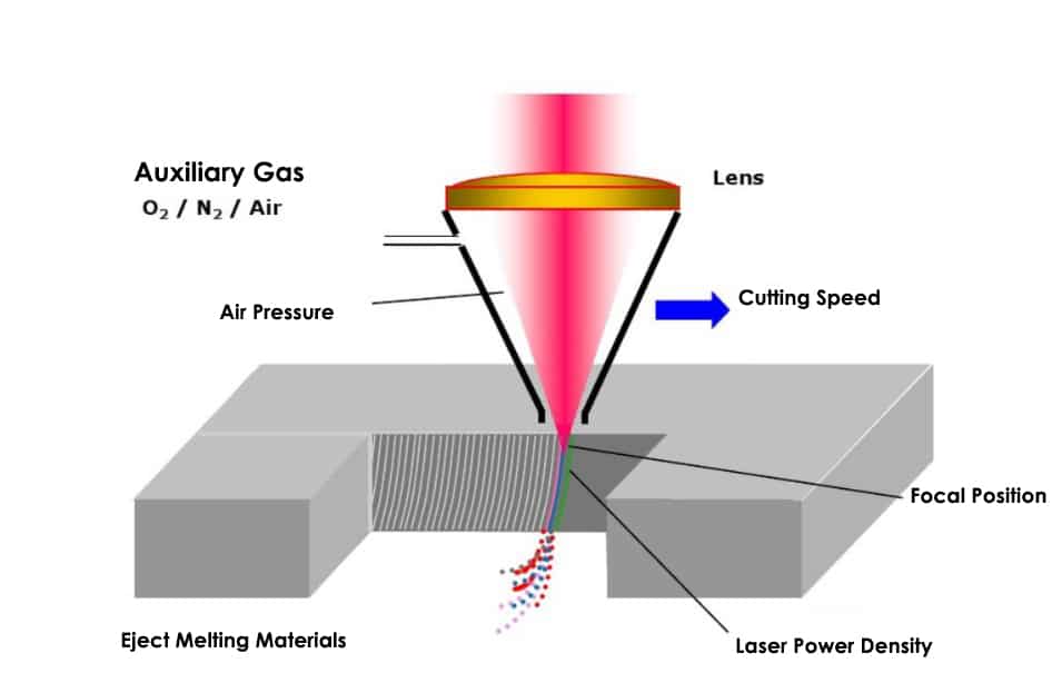
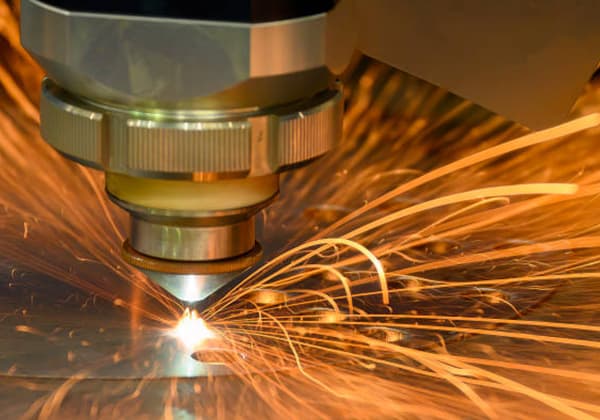
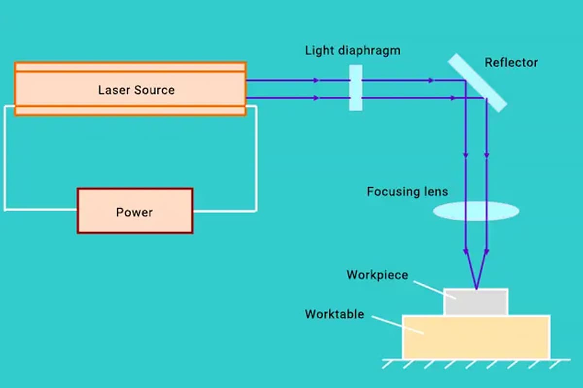
A Fiber Laser Cutting Machine operates by firing a laser beam from a laser generator. The beam is then focused into a high power density laser beam through the optical path system.
The laser beam heats the surface of the workpiece to its melting or boiling point, while a high-pressure gas is used to blow away the melted or vaporized metal. By moving the beam and adjusting the position of the workpiece, the material is finally cut to achieve the desired cutting result.
Laser cutting is a modern alternative to traditional mechanical knives, offering high precision, fast cutting, unlimited cutting patterns, automatic material saving, smooth incisions, and low processing costs.
In addition, fiber laser cutting is continually improving and replacing traditional metal cutting equipment.
The mechanical components of the laser cutter do not come into contact with the workpiece, thus avoiding scratching during operation.
Laser cutting is fast and results in smooth incisions with no need for additional processing.
The heat-affected area is small, minimizing plate deformation and resulting in narrow slits (0.1mm to 0.3mm).
No mechanical stress, no shear burr.
High machining accuracy, good repeatability, no damage to the material surface.
Numerical control programming allows for the processing of any flat shape.
Can cut a large piece from an entire plate without the need to open a mold, saving time.
Laser cutting utilizes the laser beam as a heat source for hot cutting, with a working principle similar to that of laser welding. The temperature of laser cutting exceeds 11000°C, causing materials to gasify, which plays an important role in addition to melting during the cutting process. For some materials, such as carbon and ceramics, the laser cutting process is purely a gasification process.
The laser cutting of metal is mostly performed using high-power carbon dioxide continuous laser generators. During cutting, an inert gas flow is used to blow out the incision, smoothing and straightening the melted metal. The addition of an oxygen flow from the jet increases the cutting speed.
Laser cutting offers a narrow incision, precise size, and smooth surface, resulting in better cutting quality compared to other hot cutting methods. Most metal materials can be cut by laser, with a cutting thickness ranging from a few microns to 50 mm.
Investment in laser cutting equipment is high, but it is mainly used for precision cutting of materials with thicknesses under 12 mm, including stainless steel, titanium, titanium alloys, refractory metals, and precious metals. It can also be used for cutting non-metallic materials such as plastic, wood, cloth, graphite, and ceramics. For example, the wood processing industry uses lasers to cut plywood and particle board, while the garment industry uses lasers to cut cloth.
Laser cutting is also suitable for special purposes, such as stone bearing drilling and surgery, where lasers are used as scalpels. The parameters of the laser beam, performance and precision of the laser cutting machine, and the NC system directly impact the efficiency and quality of laser cutting.
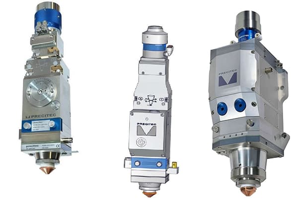
Fiber Laser Cutter Structure
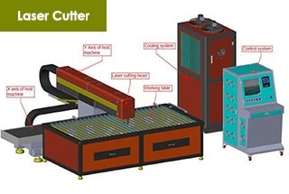
The main components of a CNC laser cutter include the machine host, control system, laser, chiller, and regulator, among others. Each of these components has its own manual or operating instructions, but the main machine structure and composition of the electrical control system will be described in detail here.
Machine Host Part:
The machine host part of the laser cutting machine is the most crucial aspect of the laser cutting process. It is responsible for achieving cutting accuracy and function. The host part consists of six components: the bed, laser, gantry part, Z-axis device, auxiliary parts of the working table (protective cover, air, and water channel), and the operation panel.
Electrical Control Part:
The electrical control system of the laser cutting machine is vital in ensuring a variety of graphic trajectories. The electrical control system mainly consists of the numerical control system and the low-voltage electrical system. The laser cutting machine is equipped with CYPCUT software and operates on the WINDOWS XP platform, ensuring stable and reliable operation. The system is equipped with a 32-bit microprocessor and an Ethernet communication interface.
The system features fast interpolation operation speed, is easy to operate, has good dynamic performance, and a strong load capacity. The control part of the low-voltage electrical system is located in the electric control cabinet and serves as the electrical control interface. The components of the electrical part adopt well-known, world-renowned brands to ensure stable operation and sensitive response.
The drive motor is an AC servo motor, which is used to drive the X-axis gantry and Y-axis skateboard of the laser cutter. It is characterized by good acceleration performance and fast response. The maximum positioning speed is up to 50m/min. The Z-axis of the laser cutting machine is the feed axis, which is driven by an AC servo motor. The Z-axis cutting head is characterized by good dynamic response and can be controlled by both servo and NC control.
The overall structure
The main component of the laser cutting machine is crucial to the entire machine. The cutting precision and function of the machine are achieved by the host component, which includes the bed (Y-axis), beam (X-axis), Z-axis, working table, air and water channel.
Frame of the Laser Cutting Machine
The bed is constructed from high-strength cast iron with a fully welded structure. It undergoes stress relief processes, including annealing, roughing, semi-finishing, and finishing. This ensures thorough stress reduction and reduces machine deformation, ensuring long-term accuracy.
The AC servo motor drive and coaxial drive beam are controlled by a numerical control system, enabling the Y-axis to move in a reciprocating motion. This results in fast and rapid movement. The machine’s movement stroke is 1500mm * 3000mm.
The gear rack and linear guide are equipped with a closed dust-proof device, featuring a lightweight dust cover and reliable operation. These precision products effectively guarantee the drive accuracy. The stroke at both ends of the machine is controlled by limit switches, and the machine is protected by elastic cushions on both sides, ensuring the machine’s movement is safe.
Beam Section
The beam component is made by welding a high-strength square tube and undergoing machining after artificial aging to enhance overall rigidity and strength. The processing process includes rough processing, vibration aging, semi-finishing, vibration aging, and finishing.
The beam is mounted on the bed’s support rail, which features both linear and flat guide rails. The servo motor drive and gear rotation through a reducer allow the Z-axis skateboard to move in the X-direction reciprocally. The movement stroke is 1450mm.
The stroke is controlled by a limit switch during movement, and both ends are protected by elastic cushions for the system’s safety. The upper and sides of the beam are enclosed by a cover, and a retractable guard is located between the beam and the transverse skateboard to ensure a fully enclosed environment for the rack and linear guide, free from external influences.
The optical path is partially sealed with a guard to create a fully enclosed optical path structure.
Exchangeable Workstation Base and Workstations (Optional)
The workstations are constructed using a robust overall welding structure for strength and stability. The exchange table is divided into two sections: a switching device and two movable cutting tables.
The exchange device is fixed on the bed’s backside and is mainly used to swap the upper and lower tables. When cutting a workpiece, the other cutting table can be utilized for feeding and unloading material to improve the laser cutting machine’s efficiency.
Each movable cutting table consists of a welding frame with a support gate for the workpiece. The worktable can hold up to 800 kg. The two tables can be automatically exchanged through a chain device drive, significantly increasing production efficiency.
The center of the table is equipped with a universal ball seat, and four universal balls in the middle support 44 workpieces. The cylinder drive and rack-and-pinion mechanism allow the swing pole to rotate 180°.
The spiral tube quick connector is fed into the cutting station’s quick connector, and the pneumatic switch is opened. The cylinder drive rotates the swing pole upward 180°, and the 44 universal balls support the workpiece, allowing it to roll on the balls and avoiding scratches caused by the workpiece sliding on a support grid.
When the workpiece is positioned, the pneumatic switch is pressed, and the cylinder swings down 180° through the rack-and-pinion mechanism, bringing the universal balls just below the pendulum to avoid damage during the cutting process.
This mechanism, where the workpiece rolls on the balls during feeding and positioning, instead of sliding on a support grid (as in traditional methods), effectively protects the workpiece’s smooth surface and reduces the operator’s labor intensity.
Z-axis Device
The Z-axis device is responsible for the lifting movement of the cutting head. This movement is controlled by the numerical control system through a servo motor, which drives a ball screw to cause the Z-axis skateboard to perform an up-and-down reciprocating motion.
The travel of the Z-axis is 100mm, and limit switches are used to control the stroke at the upper and lower ends. Additionally, flexible cushions are placed on both ends of the ball screw to ensure the safety of the movement.
High-quality ball screw and linear guides are used to ensure the accuracy of the transmission. The Z-axis can function as a CNC axis due to its separate interpolation movement and can move in tandem with the X and Y axes. It can also be switched to servo control through the cutting head’s electronic control to accommodate different requirements.
The servo control of the Z-axis is controlled by the CNC system, resulting in a high degree of accuracy and stability, ensuring the quality of the cutting. The cutting head is sealed and cushioned to prolong its lifespan.
A capacitance sensor, mounted on the cutting head, detects the distance between the nozzle and the plate surface and sends the information back to the control system. The controller then uses this information to control the Z-axis motor and keep the distance between the nozzle and the plate constant, thereby ensuring the quality of the cut.
The cutting head has a nut for adjusting the focal length, allowing for the position of the focus to be adjusted based on the material and thickness of the cutting material, leading to a good cutting section.
Note: The nozzle is a wearing part of the process, and users can keep spare nozzles of different diameters for easy replacement.
Electrical Control Section
The electrical control system of the CNC laser cutting machine is mainly composed of a numerical control system, a servo system, and a low-voltage electrical system.
The laser cutting machine is equipped with the CYPCUT CNC system, which is based on the WINDOWS XP PC CNC system and offers fast interpolation operation speed and ease of use.
The servo system employs a Japanese Yaskawa AC servo motor and drive, known for their stability, reliability, and strong load capacity.
The front panel of the laser cutting machine features two function buttons, two operation soft keys, and two front USB ports, arranged in the following order from left to right: emergency stop switch, power switch, cutting start button, and cutting stop button.
The operation soft keys have different functions depending on the mode of operation, reducing the number of operation buttons and simplifying the operation panel.
The operation functions are displayed through a menu, making the operation intuitive in various modes.
Fiber Laser Cutter Types
If based on the laser generator, the laser cutter can be divided into:
A. solid laser cutter. The solid laser cutter can be divided into the bonus stones laser cutter, YAG laser cutter.
If based on the structure, the laser cutter can be divided into:
According to the relative movement of the cutting head and the table, the CNC laser cutting machine can be divided into:
Beam fixed form (fixed light path)
Beam movement form (flying ray)
Semi-fixed and semi-mobile hybrid form
Besides, there is also an articulated movable arm fixed optical flight beam transmission form, known as a constant flight path.
In the cutting process for the laser cutter which adopts flying ray, only the cutting head moves along the X and Y direction, and the position of the table is fixed.
Such laser cutter featured:
The plate of processing is in big size, with a heavyweight.
The equipment covers a small area.
No need clamping for fabricating workpiece which is convenient for loading and discharge the materials.
The machine has good acceleration and high positioning accuracy.
Therefore, it is highly regarded by the market as the mainstream model of the international market.
Several typical structures of modern laser cutting machines are mainly included:
Gantry frame movable flying ray structure.
Beam traveling flying ray.
Beam upside down movable flying ray.
Cantilever movable flying ray structure.
Robot structure & Large format hybrid flying ray.
Laser flexible processing system.
In terms of the structure of the laser cutting equipment, the frame of the machine include:
casting structure
welding structure
marble structure
the beams are made of aluminum alloy castings or welds and profiles.
Other components use engineering plastics, fiberglass and stainless steel, etc.
The laser generator required by the laser cutter shall be selected according to the user’s processing performance, processing materials, shapes and sizes, etc.
The available laser generators include co2 axis fast-flow laser generator, RF board debugging laser generator, swirl laser generator, the solid-state laser generator and a fiber laser generator.
Based on the driving method, there are:
X and Y axis are selected with a single – side servo motor and equipped with the corresponding speed reducer, which is driven by the high precision gear rack.
The X axis is selected with the servo motor and equipped with the corresponding reducer, which is driven by the high precision gear rack. There are two gears to eliminate reverse clearance.
Directly driven by high precision ball screw with the servo motor. The machine is driven by direct gear and rack with disc large inertia motor.
Direct drive by the linear motor.
CNC laser cutting machine is usually equipped with the high precision linear guide, and equipped with an automatic lubrication device.
Single-side linear guide rail with roller structure is a cost-effective and convenient solution for economic applications. The alternative structure is the drive unit, which integrates the drive and guide rail, making installation, debugging, and precision easier to ensure, though slightly more expensive.
Installation and Commissioning of Fiber Laser Cutting Machine
The installation and commissioning of the laser cutting machine are very important for every factory, so please keep reading the following details before the operation.
Delivery check
Unpacking Precautions:
Please open the wooden box following the instructions on the outside of the box to avoid any damage to the laser cutter equipment inside.
Do not use sharp objects to remove the protective film to prevent scratching the surface of the equipment and damaging the electrical installation.
If any damage is caused by the customer, the company will not be responsible for replacement.
Contents Check:
After opening the package, please verify that it is the laser cutter that you purchased.
Inspect the laser cutter for any damage that may have occurred during transport.
Verify that all parts are present and in good condition by checking the list.
In the case of any discrepancies, such as a mismatch in the laser cutter model, missing accessories, or damage during transport, please contact the company immediately.
Installation environment requirements
Please refer to the factory’s foundation map for the installation and fixing of the laser cutting machine. Ensure that the machine is transported to the lifting position.
Please have a professional electrician carry out the power distribution wiring in accordance with the requirements, and take care not to damage the machine during installation and fixing.
Installation methods and precautions
Install and secure the laser cutting machine according to the factory foundation map and in accordance with our recommended principles for layout, installation, and securing. Ensure that the installation and securing process does not cause damage to the laser cutting machine.
Commissioning methods and related instructions
Machine commissioning must be performed by professional staff and must be carried out strictly in accordance with relevant provisions. Before commissioning, it is recommended to have a thorough understanding of the performance of the laser cutting machine and to read the accompanying technical information. Proper commissioning is essential to ensure the normal operation of the machine. If any assistance is needed, please contact us promptly and we will provide a satisfactory solution in a timely manner.
Note: This debugging process includes commissioning procedures after power-on.
Connection of Parts in the Distribution Cabinet
To start, identify the parts according to the requirements, as outlined below:
After installation is completed, connect each distribution cabinet as follows:
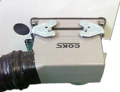
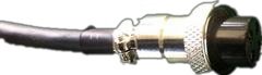
(A) Check if the three joints at the end of the Y-axis extension have been damaged during transportation (the three connectors are: a 16-core heavy-duty connector, a 19-core aviation plug, a 4 encoder plug, and an amplifier plug) as shown below:
Aviation Plug
Heavy-duty Connector
Encoder Plug
Amplifier Plug
(B) Insert the plugs into their corresponding positions (the positions are unique). The encoder plug should be inserted into the appropriate servo drive based on the number, and the amplifier plug should be inserted into the height adjuster.
(C) Connect the power cord of the water cooler in the distribution cabinet to the designated location, as illustrated below:
Power Plug
Power Plug Connection Position
(D) Connect the main power, which is a three-phase four-wire system, with the yellow and green wires serving as the zero line and the remaining three serving as the live line. With this, the electrical external circuit connection is completed. In the next section, we’ll discuss the water connection.
Warning:
The ground wire of the power cord must be grounded securely to prevent disturbance of the signals inside the machine cabinet and reduce the risk of leakage.
The connection method of water cooler
Installation Requirements
The chillers should be placed smoothly and have a sufficient distance from the wall. The installation site of the chillers must have adequate air inlet and outlet space to prevent poor cooling and avoid high temperatures in the distribution cabinet.
Inspection of the Equipment
Prior to installation, it is important to clean any debris inside the water tank and ensure that the water is free of impurities. Then, inspect the water pipe system joints to make sure they are tight.
Installation Procedure
Connect the inlet and outlet pipes on the chiller according to the signs on the chiller’s shell and connect them to the inlet and outlet doors of the laser, ensuring that the direction of the inlet and outlet of the water pipe is not dislocated. Before connecting the water pipe, make sure that the outside of the chiller is free of debris and foreign matter.
Water Quality Standards
Check that the sewage valve is closed and add water to the tank. The water level should be less than 30mm to 50mm in the tank to prevent overflowing. It is strictly prohibited to use general tap water in the chilled water units, and high-quality pure water, distilled water, or deionized water must be used. Adding any corrosive liquids is strictly prohibited.
Power On Commissioning
There is an air switch behind the water cooler. When the water channel is connected well, turn on the switch to test operation. After the pump starts, check for any water leaks in the joints and if found, turn off the power and fix the problem before turning it on again.
Water Temperature Regulation
In an air-conditioned room, the water temperature is generally set at 22-24 degrees Celsius. In a non-air-conditioned room, the water temperature is set lower than the room temperature by 2-5 degrees Celsius. If the water condenses on the pipe wall, it indicates that the temperature of the water cooler is set too low.
Nozzle effect and adjust laser at nozzle mouth
Nozzle action and regulation
A) Nozzle
The design of the nozzle and the flow conditions of the jet have a direct impact on the quality of the cutting; the accuracy of the nozzle manufacturing is closely related to the cutting quality.
B) Main Functions of the Nozzle:
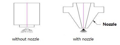
▲ To prevent cutting debris and other debris from bouncing into the cutting head and damaging the focus lens.
▲ The nozzle can change the situation of cutting gas discharge, control the size and area of gas diffusion, thus affecting the cutting quality.
The figure below shows the case of ejection when the nozzle is installed and not installed.
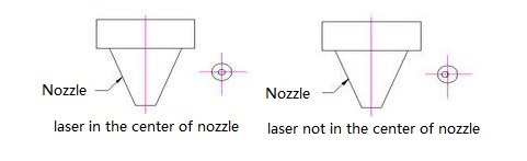
Steps to adjust the nozzle to pass the laser from the center of the nozzle
Compared to CO2 laser cutting machine, fiber laser cutting machine is no optical path, only need to adjust the laser at the nozzle mouth.
Compared to CO2 laser cutting machines, fiber laser cutting machines do not have an optical path, and only require adjusting the laser at the nozzle.
Coat the end of the nozzle with Indian mud (or transparent tape if not using mud), then attach white stickers to the end.
Adjust the laser output power to between 30W to 50W, open the mechanical shutter, and quickly switch the electronic shutter once while observing the phenomenon.
Turn off the mechanical shutter, remove the white stickers while being careful not to change its relative position.
If the difference between the nozzle position and laser center is too large, the stickers will not be able to align with the center hole. Since the laser center is fixed, the center of the nozzle can be adjusted by turning the adjustment screw on the cutting head handle to match the laser center.
Repeat the above steps until the laser hole on the white sticker coincides with the center of the nozzle, confirming that the laser center aligns with the nozzle center.
See below:
Effect of the nozzle on cutting quality and nozzle size selection
The relationship between the nozzle and cutting quality:
When the center of the nozzle is different from the center of the laser: theimpact on cutting quality
Cutting Section
When the cutting gas is jetted, an uneven gas volume can result, causing the cutting section to be more prone to stair-stepping on one side and not on the other. The impact of this is small when cutting sheets below 3mm, but when cutting plates above 3mm, the impact is more serious, and cutting may not even be possible.
Sharp Corners
In the cutting of sharp corners or workpieces with smaller angles, local over-melting is prone to occur, and cutting thick plates may not be possible.
Perforation
During piercing, instability makes it difficult to control the time, and penetration of thick plates can cause melting. This can also make it difficult to control penetration conditions, and the impact on small pieces is small.
In conclusion, the center of the nozzle and the concentricity of the laser are important factors in cutting quality, especially when the workpiece is thicker. Therefore, it’s necessary to adjust the center of the nozzle to align with the laser concentricity to achieve better cutting.
Note:
Deformation of the nozzle or fouling can have the same impact on cutting quality as described above. Therefore, the nozzle should be handled with care to avoid deformation, and any stains should be cleaned promptly. The manufacture of the nozzle requires higher precision, and proper installation methods must be followed. If the nozzle’s poor quality leads to changes in cutting conditions, the nozzle should be promptly replaced.
Selection of nozzle aperture
The difference in nozzle diameter is shown below:
Nozzle Aperture
Air Flow
Liquid Melt Removal Capacity
Small
Fast
Strong
Large
Slow
Weak
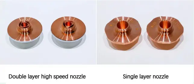
The diameter of the nozzle has φ 1.0mm, φ 1.4mm, φ 2.0mm, φ 2.5mm, φ 3.0mm and so on. The current nozzle diameter often uses φ 1.4mm, φ 2.0mm. As shown below:
The difference between the two diameters mentioned above is as follows:
For thin plates below 3mm:
Using a φ4mm nozzle will result in a smaller cutting surface.
Using a φ2mm nozzle will result in a thicker cutting surface, with a higher likelihood of melted stains at the corners.
For thick plates above 3mm:
The cutting power is higher, which results in a longer heat dissipation time and a longer cutting time.
Using a φ1.4mm nozzle will result in a small gas diffusion area, which may cause instability during use, but is still generally usable.
Using a φ2mm nozzle will result in a larger gas diffusion area and a slower gas flow rate, which results in more stable cutting.
A nozzle with a diameter of 2.5mm can only be used for cutting plates thicker than 10mm.
In conclusion, the nozzle size has a significant impact on the quality of cutting and perforation. Currently, laser cutting machines mostly use nozzle apertures of φ1.4mm and φ2mm.
Note:
The larger the nozzle aperture, the more likely it is that sparks and melt splashes during cutting will cause damage to the lens, reducing its lifespan.
Beam focus adjustment
In the laser cutting process, the relationship between the beam focus and the surface of the cutting sheet greatly affects the cutting quality, and it is crucial to adjust the focus position correctly.
This is typically done by adjusting the focus through a test cut, where the focus is at its proper position when the cut has the least hanging slag and the smallest size on the corresponding steel plate.
If the position of the cutting head relative to the board changes, it is also necessary to adjust the zero points of the cutting head and the sensor. Fine-tuning can be accomplished by adjusting the cutting height in the software.
When larger adjustments are necessary, it may be necessary to adjust the position of the sensor and its bracket to properly adjust the focus.
Take care when performing these adjustments, as a misstep could cause the cutting head to hit the surface and result in damage to the parts.
The relationship between the focus position and the cutting effect
Focus on the surface of the cutting bow and arrow, the upper surface is smooth, the lower surface is not smooth
Positive focal length: the focus in the inside of cutting bows
Aluminum cutting instructions
The focus in the central, so there is a larger smooth surface, cutting width wider than the zero focal, large air flow during cutting, perforation time longer than the zero focal
Stainless steel cutting with high-pressure nitrogen, blown away molten slag to protect cutting section, cut width increased with the workpiece thickness
Cutting speed selection
The selection of cutting speed in laser cutting machine is crucial and depends on the material and thickness of the plate being cut. The cutting speed has a significant impact on the quality of the laser cutting.
Choosing an appropriate cutting speed not only enhances the efficiency of the laser cutting machine, but also ensures a high-quality cut.
Here are the effects of different cutting speeds on the cutting quality:
The effect on cutting quality with too fast laser cutting feed rate
may cause no cutting, sparks scattered.
Some areas can be cut off, but some areas cannot be cut off.
resulting in the entire cutting section thicker, but no fusible generation.
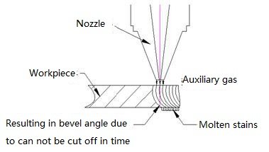
cutting feed rate is too fast, resulting in the plate cannot be cut off in time, cutting section showing oblique lines, and the lower part generate fused stains. As shown below:
The effect on cutting quality with too slow laser cutting feed rate:
result in over-melting of the cutting plate and a rough cutting section.
The width of the slit will increase, causing the entire area to melt in smaller fillets or sharp corners, resulting in poor cutting quality.
low cutting efficiency, affecting production capacity.
To determine the appropriate cutting feed speed, observe the cutting sparks: if they spread from top to bottom and tilt, the feed rate is too fast. If the sparks are condensed and not spreading, the feed rate is too slow. With the correct cutting speed, the cutting surface will show a smoother line, and the bottom half of the plate will not fuse.
As shown below:
Laser cutting gas and pressure selection instructions
The choice of cutting gas in laser cutting depends on the material being cut. The selection of cutting gas and pressure has a significant impact on the cutting quality.
The main function of the cutting gas is to aid combustion and dissipate heat by blowing away the residue and preventing it from entering the nozzle and damaging the focus lens.
Impact of Cutting Gas and Pressure on Cutting Quality
A suitable cutting gas helps with combustion and heat dissipation, leading to a better quality cut.
When the pressure of the cutting gas is insufficient, the cutting process will be affected by the buildup of residue, and the cutting speed will not meet the production requirements.
When the pressure of the cutting gas is too high, the cutting surface will be rough and the slot will be wide, causing part of the cut to melt, resulting in poor cut quality.
Impact of Cutting Gas Pressure on Perforation
If the gas pressure is too low, the laser will struggle to penetrate the cutting plate, resulting in longer drilling times and lower productivity.
If the gas pressure is too high, the penetration point will melt and form a larger melting point, which will affect the cutting quality.
For laser drilling, a high sheet metal punching pressure is generally used, while a lower pressure is used for punching thick plates.
When cutting ordinary carbon steel, the thicker the material, the lower the pressure of the cutting gas.
When cutting stainless steel, the cutting gas pressure remains high, regardless of the material thickness.
In conclusion, the selection of laser cutting gas and pressure must be adjusted according to the specific conditions and circumstances of each application.
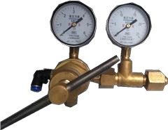
Our laser cutting equipment is delivered with two gas pipelines, one for oxygen and air, and one for high-pressure nitrogen use. These two gas channels must be connected to a pressure reducing valve, as shown in the figure below.
Pressure relief valve description: the left side of the table shows the current pressure, the right table shows the remaining gas capacity.
“Warning”
Nitrogen supply pressure should not exceed 20kg;
Oxygen supply pressure should not exceed 10Kg, or likely to cause the gas pipe burst.
Laser cutting power impact on cutting quality
The choice of laser power size has an impact on the cutting quality, and it is important to determine the cutting power based on the material and thickness of the plate. Having too small or too large of a laser power will result in poor cutting quality.
A) Too small of a laser power will result in no cutting. B) When the laser power setting is too large, the entire cutting surface will melt and the slit will be too wide, resulting in poor cutting quality. C) When the laser power setting is insufficient, cutting fouling will occur and scars will appear on the cutting section.
Therefore, setting an appropriate laser power, along with the appropriate cutting gas and pressure, will result in a good cutting quality with no fused stains.
To reduce the variation in focal spot size caused by changes in beam size before focusing, laser cutting systems manufacturers offer several options for users to choose from:
Parallel optical tube. This option involves adding a parallel optical tube to the output end of the CO2 laser, which increases the beam diameter and reduces its divergence angle, resulting in near and far ends of the beam being close to the same size.
Independent moving lens. An independent moving lens can be added to the lower shaft of the cutting head, separate from the Z-axis that controls the distance between the nozzle and material surface. This lens moves in tandem with the machine tool table or light axis, ensuring the focal spot diameter remains consistent throughout the processing area.
Control of focusing mirror water pressure. This method, usually in a metallic reflection focusing system, reduces the focal curvature of the focal spot by automatically adjusting water pressure, thus reducing the beam size and increasing the focal spot size.
X and Y-directional compensation optical path system. This option involves adding a compensation optical path system to the flying ray cutting machine. The length of the compensation optical path decreases as the distance of the far end cutting increases, while increasing the compensation flying ray to keep the length of the optical path consistent when cutting the near end.
2. Cutting perforation technology.
Almost all hot cutting technologies, except for a few exceptions, must start by drilling a small hole in the board. In the past, a laser punch was used to punch out the hole before the laser cutting began. There are two basic methods for laser cutting machines without a stamping device:
Blast Drilling:
After continuous laser irradiation, a pit is formed in the center of the material, which is then quickly removed by the oxygen flow along with the laser beam. The average hole size is dependent on the plate thickness, and the average diameter of blast holes is half the plate thickness. This method is not suitable for high-precision parts (such as oil screen seam pipes) because of its large hole diameter and poor roundness. It is only used for scrap. Additionally, the oxygen pressure used for perforation is the same as that for cutting, leading to significant splashing.
Pulse Drilling:
A pulsed laser with a peak power is used to melt or vaporize a small amount of material, with air or nitrogen used as an auxiliary gas to reduce hole expansion due to exothermic oxidation. The oxygen pressure used is lower than during cutting. Each pulsed laser creates only small, deep particles, so it takes a few seconds to perforate thick plates. Once the perforation is complete, the auxiliary gas is immediately replaced with oxygen for cutting. This method results in a smaller perforated diameter and better perforation quality than blast drilling.
The laser must have high output power as well as time and spatial characteristics of the beam, so the general CO2 laser generator cannot meet the requirements of laser cutting. Additionally, pulse perforation must have a reliable gas control system to control gas type, pressure switching, and perforation time. The transition technology from pulse perforation to continuous cutting should be emphasized in order to achieve high-quality incisions.
In theory, the cutting conditions that normally change during the acceleration section include focal length, nozzle position, and gas pressure. However, it is unlikely that these conditions will change in such a short period of time.
3. Nozzle design and air flow control technology.
When cutting steel with a laser, the laser beam and oxygen are directed through a nozzle and onto the material to form an airflow. For the incision to be effective, the airflow must be high in speed and volume to promote oxidation and remove the molten material. The quality of the cut is affected not only by the laser beam but also by the design of the nozzle and air flow control (such as the nozzle pressure and the position of the material in relation to the airflow).
The laser cutting nozzle has a simple design, with a small round hole at the end of a tapered opening. The nozzle is usually made of copper, which is prone to wear and tear, so it needs to be frequently replaced. As a result, fluid mechanics calculations and analysis are not typically performed. The nozzle pressure is referred to as the pressure of the gas being ejected from the side of the nozzle, measured in gauge pressure (Pg).
When used, the gas is expelled from the nozzle and reaches the surface of the material at a certain distance, referred to as the cutting pressure (Pc). The gas then expands to atmospheric pressure (Pa). Research shows that as the nozzle pressure increases (Pn), so does the flow velocity and cutting pressure. A formula can be used to calculate the airflow speed:
V = 8.2d2 (Pg + 1)
Where: V = gas flow velocity in L/min d = nozzle diameter in mm Pg = nozzle pressure (gauge pressure) in bar
There are different pressure thresholds for different gases. When the nozzle pressure exceeds a certain value, the airflow transitions from subsonic to supersonic. This threshold is dependent on the ratio of Pn to Pa and the freedom degree of the gas molecules. For example, in the case of oxygen, the threshold is Pn = 1 bar x (1.2)3.5 = 1.89 bar. If the nozzle pressure is even higher (Pn/Pa = (1 + 1/n)1 + n/2, where Pn = 4 bar), the airflow transitions from a normal oblique shock wave to a positive shock wave, which reduces the cutting pressure, airflow speed, and causes vortex formation on the surface of the material, which weakens the airflow’s ability to remove the molten material and affects the cutting speed.
Therefore, the tapered nozzle with a small round hole is used, and the pressure of the oxygen nozzle is often kept below 3 bar.
To determine the model, size, and quantity of laser cutters to be purchased, it is important to understand the scope of your company’s production, processing materials, and cutting thickness. It is advisable to make a simple setup for the later purchase.
Laser cutting machines are used in various industries such as mobile phones, computers, sheet metal processing, electronics, printing, packaging, leather, clothing, industrial fabrics, advertising, crafts, furniture, decoration, medical equipment, and instruments.
The most popular models in the market are the 3015 and 2513, which are 3×1.5m and 2.5×1.3m (width x length of the bed side) respectively. However, the size of the laser cutter is not an issue as suppliers typically offer laser cutters of different sizes for customer selection, and they can also be customized.
Regarding the price of fiber laser cutting machines, you can find more information in a related post. Professional personnel can conduct on-site simulation solutions or provide solutions, and they can also bring their own materials to the manufacturer for sample making.
Thin cutting seam – The laser cutting seam is typically 0.10mm-0.20mm.
Smooth cutting surface – The presence of burrs on the cutting surface of laser cutting can vary. Generally, YAG laser cutting machines have some burr, which is mainly determined by the cutting thickness and gas. Generally, there are no burrs under 3mm. Nitrogen cutting is the best, followed by oxygen cutting and air cutting being the worst. The fiber laser cutting machine has the least burrs, with a very smooth cutting surface and fast speed.
Check the deformation of the material.
Laser power – For example, if the factory primarily cuts metal plates below 6mm, there is no need to buy a high-power laser cutting machine. A 500W fiber laser cutting machine can meet the production demand. If the production is larger, and there is a concern about the efficiency of the 500W laser cutter, the best option would be to purchase two or more smaller and medium-power laser cutting machines. This will help the factory save costs and improve profits.
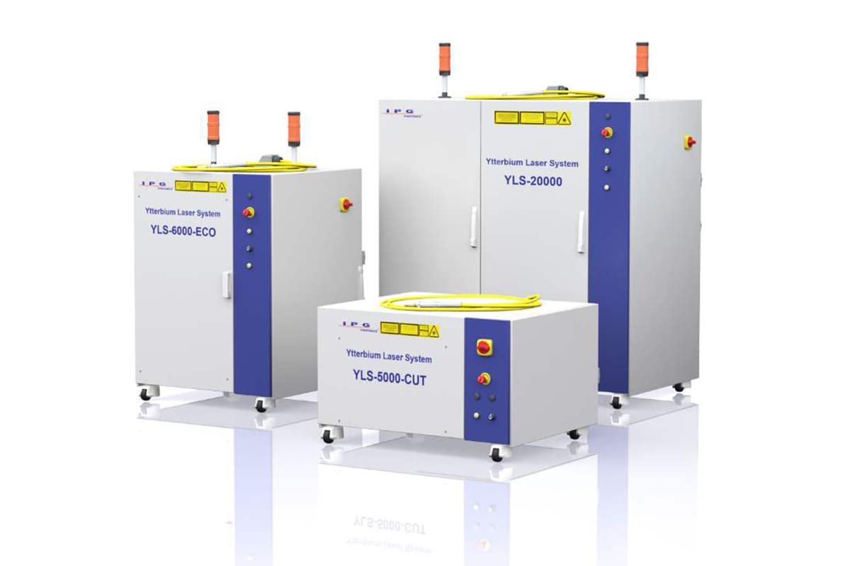
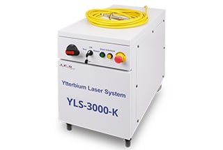
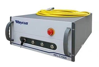
The core parts of the laser cutter – The laser generator and laser head are the core components of the laser cutter. Most laser generators use imported IPG brands, while the economical type is the Raycus brand from China. It is also important to pay attention to other components such as the electrical motor (whether it is a servo motor), linear guide, frame, etc., as these components can also affect the cutting accuracy. The cooling system of the laser cutting machine, the cooling cabinet, should also be noted. Many companies use home air conditioners for cooling, but this is not effective. The best way is to use industrial air conditioners for optimal cooling.
Repair and charges – Any equipment will incur damage during use to varying degrees. In case of damage, the timeliness and cost of the repair should be considered. It is therefore necessary to understand the after-sales service of the company through various channels, such as whether the maintenance fee is reasonable.
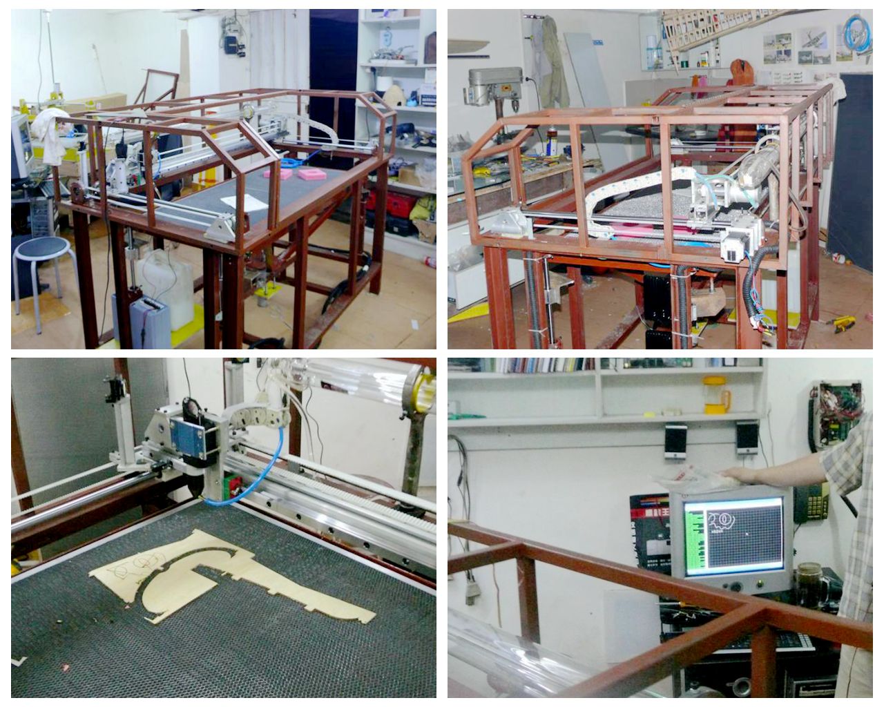
How to DIY Fiber Laser Cutter?
If you require a laser cutter, it is straightforward to purchase one. DIY can be challenging and may not result in cost savings. There are individuals who are enthusiastic about laser cutters and have created a metal laser cutter by designing the software, circuit, and machinery themselves. This process took approximately three months.
However, if you are looking to learn and gain hands-on experience, building a machine from start to finish can be a fulfilling experience. Check out the following resources for DIY laser cutters:
Laser Cutter Kit
Laser Cutter Wearing Parts List
No.
Item
1
Protective Lens
2
Filter Element
3
Copper Nozzle
4
Focus Lens
5
Ceramic Ring
6
Collimating Lens
7
Amplifier
8
Amplifier Connector
Operation Cost Analysis of Laser Cutter.
1) Take 1mm stainless steel as an example to calculate capital used and time-cost
For example:
Consider cutting 50,000 meters of 1mm stainless steel. The calculation of the time period may vary due to the short hole drilling time for thin sheet metal and differences in production arrangements that may not record empty stroke. Thus, the statistical results may not accurately reflect efficiency and cost comparisons.
Note: The loading and unloading time is not included in the calculation.
Fiber laser cutter with a 2000W power:
50,000 m ÷ 20 m/min ÷ 60 min = 41.7 h ≈ 5 days
41.7 h x (27.8 RMB + 70 RMB) ≈ 4078 RMB
CO2 laser cutter with a 3000W power:
50,000 m ÷ 8 m/min ÷ 60 min = 104.2 h ≈ 13 days
104.2 h x (63.5 RMB + 70 RMB) ≈ 13911 RMB
CO2 laser cutter with a 2000W power:
50,000 m ÷ 6.5 m/min ÷ 60 min = 128.2 h ≈ 16 days
128.2 h x (50.5 RMB + 70 RMB) ≈ 15488 RMB
1mm SS
Fiber laser 2000W
CO2 laser 3000W
CO2 laser 2000W
Time(day)
5
13
16
Cost(RMB)
4078
13911
15488
2) Take 2mm stainless steel as an example to calculate capital used and time-cost
For example:
Cutting 2mm stainless steel, with a total of 50,000 meters, over a roughly estimated time period:
Fiber laser cutter with a power of 2000W:
50,000m ÷ 8.5m/min ÷ 60 min = 98 hours ≈ 12 days
98 hours × (27.8 RMB + 70 RMB) ≈ 9588 RMB
CO2 laser cutter with a power of 3000W:
50,000m ÷ 4.5m/min ÷ 60 min = 185.2 hours ≈ 23 days
185.2 hours × (63.5 RMB + 70 RMB) ≈ 24724 RMB
CO2 laser cutter with a power of 2000W:
50,000m ÷ 3m/min ÷ 60 min = 277.8 hours ≈ 34.7 days
To ensure the proper functioning of a laser cutting machine, it requires routine maintenance. As the machine uses high-precision components, it is important to handle the maintenance process carefully and follow the operating procedures strictly. It is also recommended to appoint a specific person to perform the maintenance to prevent any damage to the components.
Users should always have the following spare parts on hand:
A) Acetone (99.5% purity, with less than 0.3% water and 500ml capacity) B) Absorbent cotton (5 packs, medical grade or optical grade) C) Alcohol (500ml, with 99.5%+ purity) D) Dropper (medical) E) Cotton swab (two packs) F) Multimeter (one).
The instructions for installing or replacing the internal lens of the cutting head are also provided.
(1) Before installing the optical lens, it’s important to: wear clean clothes, clean your hands with soap or detergent, and wear clean white gloves; do not touch any parts of the lens with your bare hands; take the lens from the side, without touching the lens coating surface directly.
(2) When assembling the lens, avoid using your mouth to blow on it; place the lens on a clean desktop and put a few sheets of professional paper under it.
Handle the lens carefully to prevent bruising or falling, and do not apply any force to the lens coating surface. Clean the lens holder before installing the lens, using a clean air spray gun to remove any dust and dirt. Then, gently place the lens into the lens holder.
(3) When installing the lens in the lens holder, do not use excessive force to secure the lens, as this can cause lens deformation and affect the beam quality.
(4) Precautions when replacing the optical lens:
Handle the lens with care when removing it from the box to prevent scratching
Do not apply any pressure to the lens until the wrapping paper is removed
Wear clean gloves when removing the protective lens and focusing lens from the box and remove it from the side of the lens
Avoid dust and other objects falling on the lens when removing the packaging paper
Use a clean air gun to remove dust from the lens and put it on optical lens paper
Remove any dust and dirt on the lens holder and supports to avoid foreign matter falling on the lens during assembly
Do not use too much force when installing the lens in the lens holder to prevent lens deformation
After lens assembly is complete, use a clean air gun to remove any dust or foreign matter on the lens.
Steps to clean the lens of the laser cutting machine:
First, blow out the dust on the mirror with a clean air gun. Then, use a clean cotton swab to remove any dirt. Dip the cotton swab in new high-purity alcohol or acetone and make circular motions starting from the center of the lens and moving outward.
Repeat the process until the lens is clean, exchanging to a new clean cotton swab after each round. Use a clean cloth to remove any residual marks on the mirror, taking care not to scratch it. Observe the lens with plenty of light to see if the reflection is good, indicating that the lens has been cleaned. If the reflection is not good, continue the cleaning process.
Finally, place the cleaned lens in the mirror base using the above method. It is prohibited to use the same cotton swab for cleaning again.
Storage of optical lenses
Proper storage of the optical lens is essential to maintain its quality.
The storage environment should be between 10-30°C, as placing the lens in a freezer or similar environment may cause condensation, which can easily damage the lens.
The temperature of the storage environment should not exceed 30°C, as this may affect the lens surface coating.
When storing the lens in a box, it should be placed in a non-vibrating environment to prevent deformation of the lens and maintain its performance.
Electrical inspection
Maintenance mainly involves checking the stability of the daily power supply voltage, maintaining cleanliness and proper ventilation of the machine’s electrical cabinet, and ensuring the integrity and safety of each electrical component.
Maintenance cycle
A) The maintenance cycle of the laser, chiller, and air compressor should be in accordance with the schedule specified in the instruction manual.
B) The first maintenance of the machine should be performed after 24 hours of use, followed by another maintenance after 100 hours of use, then an overhaul after six months, and thereafter maintenance should be performed every six months or once a year (depending on specific customer circumstances).
Maintenance during operation
Before operating the machine, it’s important to perform a daily check and maintenance on the laser cutting machine according to the daily inspection list. If you notice any abnormal sounds while the machine is in use, stop it immediately and conduct a thorough inspection. After you have finished using the laser cutting machine, be sure to turn it off in the correct order and clean up both the machine table and the area surrounding it. Do not leave any unrelated items on the machine table or control panel.
Regularly check the oil level of the lubrication pump and refill it as necessary to ensure that the X-axis and Y-axis guides are fully lubricated, maintain the accuracy of the machine, and extend the life of the X and Y-axis guides.
Clean the Z-axis linear guide and the dust on the screw shaft once a week and add engine oil.
Check the water and air pipes once a week for damage, and promptly notify the company staff for maintenance if any damage is found.
Clean the air every week to filter out debris and dust.
Check the internal cooling water level of the water cooler every week and add more if necessary.
Check the contamination of the focusing lens every two weeks and clean it as necessary to ensure its service life.
Check the protective mirror once a day to maintain its cutting effect.
Check the gas path once a month to remove any potential dangers.
Regularly check the external cables for damage, and check the distribution cabinet line interfaces for looseness.
Adjust the levelness of the machine after six months of use to ensure its cutting accuracy.
Maintenance for long-term not use
When the machine is not in use for extended periods of time, apply a protective coating, such as oil or grease, to the moving parts. Wrap them in anti-rust paper and regularly check for any rust, removing it promptly and performing rust prevention measures on affected areas. (Consider adding a dust cover if budget allows.) Maintain regular cleaning and inspections of the machine.
Problems
Causes
Solutions
Parts are processed without auxiliary gas output
1. lack of pressure;
1. check the air pressure;
2. the solenoid valve or wireline is broken;
2. check the solenoid valve or solenoid valve line
There is an abnormal sound in the movement of the axis
1. no lubricants on the moving parts;
1. add lubricants;
2. check the movement path is safe
2. check the moving parts path safety
There is no laser at the cutting head. or the light is weak
1. no light signal;
1. check the PWM signal line;
2. laser or fiber is broken;
2. check whether the laser alarm;
3. nozzle block; optical path partial;
3. replace the nozzle; 4. adjust the optical path
The cutting pattern does not match the size of the drawing
1. the program errors;
1. read the instructions. check the operation is correct;
2. the positioning accuracy has been affected;
2. check the accuracy of the machine is qualified;
Note: There is no one ‘best’ option, only better options, choose the one that is most suitable for you.
Laser cutting is a mature manufacturing process and the performance of the top-brand laser cutting machines is not much different. The choice of the best laser cutting machine is primarily based on the production materials. The following factors need to be considered:
Cutting Seam: The typical laser cutting seam is 0.10-0.20mm.
Smooth Cutting Surface: There should be no burrs on the cutting surface.
Low Heat Deformation: The laser cutting process is characterized by a thin cutting seam, fast speed, and concentrated energy, resulting in minimal heat transfer to the material and low deformation.
Suitable for Large Product Processing: Laser processing eliminates the need for molds in the manufacture of large products, which can greatly reduce production costs and improve the quality of the product.
Suitable for New Product Development: Laser processing can be performed immediately after the product design is complete, allowing for a shorter development cycle.
Material Savings: Laser processing utilizes computer programming to maximize material utilization through cutting products into different shapes.
Fiber Laser Cutting Machine Operation
Before using the laser cutting machine, it is important to understand the operation of its various parts and follow the proper operation methods for both machine performance and personal safety.
Before use, perform the following checks:
Check the oil level of the machine and fill as necessary to keep it within the normal range.
Check the water and gas channels for leaks and ensure the quality of the air and water is normal and not contaminated.
Verify that the laser beam is being emitted from the center of the gas nozzle by checking the coaxial alignment of the laser and the nozzle.
Ensure the mouth of the cutting gas nozzle is appropriate for the cutting process and replace if necessary.
Check the connection of the auxiliary gas for cutting and adjust the gas pressure to the proper level if needed.
Safety precautions and safety signs before use and in use
Represents “Attention”, does not follow the correct operation could result in personal injury or damage to the equipment
Represents there is a laser beam through, do not pass from the beam, otherwise, it will cause burns on the human body or even life-threatening
Represents there is a high-voltage power supply danger, do not close to high pressure, otherwise, it will cause electric shock or even life-threatening
Precautions:
A) Never look directly into the laser, including the red light.
B) Keep people and non-work items out of the laser’s range when opening the shutter.
C) The operator must wear protective glasses and remain present during the operation of the laser cutting machine.
D) If an issue arises during use, immediately hit the emergency stop switch or turn off the main power supply.
E) Continuously monitor the cooling water temperature and working gas pressure during use.
F) Only operate the machine with proper training and following safe operating procedures. Unauthorized personnel are strictly prohibited from operating the machine.
G) The laser on the laser cutting machine is a Class 4 laser product, and the invisible laser beam, lens reflection, and scattered light can be harmful to the human body, particularly the eyes. Personnel must take necessary precautions and prevent fire incidents.
H) The exhaust gas generated during laser cutting can be harmful to the operator, so make sure the machine’s vacuum cleaner is functioning properly.
I) Maintain the laser cutting equipment in a clean and organized manner, lubricating as directed and properly managing tools and accessories to avoid loss. If any malfunctions occur, stop the machine immediately and inform relevant engineers if the operator is unable to resolve the issue.
J) To prevent electrical shock damage, only professional maintenance personnel are allowed to inspect or repair the electrical control part of the laser cutting machine.
Switch On/Off Sequence:
A) Start by turning on the external power source to supply electricity to the control cabinet.
B) Ensure that the water cooler switch is turned on (do not turn off the water cooler switch after use).
C) Check that the emergency stop switch is in the released position.
D) Turn the key switch to the “on” position.
E) Turn on the computer.
F) Finally, turn on the laser power to the left.
To shut down the laser cutting machine, reverse the order of these steps.
Software Use and Programming:
For instructions on using the software, please refer to the manual. The details will not be discussed here.
Automatic Calibration for Height Sensor:
If you need to calibrate the height sensor when changing the nozzle or if the servo distance is not accurate, calibration can correct the height of the follower. The steps are as follows:
A) Move the cutting head down to approximately 5mm from the surface of the plate.
B) Select “Calibration” on the height control torch → “Floating Head Calibration” → “Confirm”.
C) The cutting head will drop twice during the process, which takes about 10 seconds. Check the position of the plate during this time.
D) The calibration curve will be displayed on the height control torch when the calibration is finished. The curve should be smooth for a normal calibration result. If the calibration result is poor, it will affect the cutting effect and the calibration needs to be done again.
There are several factors that can affect the calibration results, including:
An unstable surface on the board.
Shaking of the Z-axis slide.
Serious electrical interference from external sources.
Calibration results are classified as A, B, C, or D. The laser cutter can be used normally if the calibration result is above “C”, and re-calibration is required to eliminate interference if the result is “D”.
Laser Cutting Machine Safety
This section focuses on the importance of laser safety and provides guidelines for the safe operation of laser cutting machines. It is crucial that every operator is aware of common knowledge and safety measures to ensure their well-being.
“Precautions”
A) Appoint safety administrators to establish their responsibilities and provide safety training to laser processing operators.
B) Define the laser safety management area and display warning signs at the entrance. The signs should include information about the machine’s power, laser type, prohibition of entry for outsiders, and the importance of eye protection. The name of the safety manager should also be included.
C) Operators of laser processing machines must undergo specialized training and only operate the machine with the permission of the safety administrator.
Laser safety notice
The main harm from laser to the human body is to the eyes and skin. Laser exposure can result in burns on any part of the body, so it is important to avoid placing any part of the body in the light path of laser equipment to prevent damage from misuse.
Eye and Skin Protection
During laser processing, CO2 and YAG lasers are commonly used, and each type of laser can cause different harm to the human body. The YAG laser is more harmful as its wavelength has a high transmittance to human eyes, which may damage the retina. On the other hand, CO2 lasers cause damage mainly in the form of cornea burns to the eyes. Both types of laser exposure can lead to eye cataracts and the risk of skin burns. Hence, it is important to use the appropriate protective measures according to the type of laser being used during the adjustment process.
Fire Prevention
Laser cutting often involves the use of oxygen and sparks during the cutting process, which increases the risk of fire. Therefore, the work area should not contain flammable or explosive materials and should have the necessary preventive facilities in place.
Electrical Safety
A) Avoid Touching Switches with Wet Hands to Prevent Electric Shock
The areas of the laser cutting machine marked with lighting signs indicate that these parts have high electrical voltage or electrical components. Operators who are close to these parts or performing maintenance should be cautious to avoid electric shock. This includes the protective cover at the servo motor’s position, the junction box behind the column, the laser cutting machine’s transformer cabinet, and the electrical cabinet doors, etc.
B) Familiarize Yourself with the Functions and Keys
Make sure to read the machine manual and electrical schematic comprehensively so you can familiarize yourself with the functions and keys of the laser cutting machine.
C) Prohibit Unauthorized Changes to the Machine Parameters
Do not easily open the electrical doors, and prohibit unauthorized changes to the machine parameters, servo parameters, and potentiometer (matching with the exchange table). If a change is necessary, you must be trained by the laser cutting equipment manufacturer and approved by the professional staff. Remember to record the parameter values before making any changes so the original state can be restored if needed.
D) Protect Yourself from High Voltage and X-rays
The general power supply voltage of the processing laser cutter is several thousand to tens of thousands of volts, so it’s important to prevent exposure to the laser’s high voltage and X-rays generated by the electron tube under high voltage.
E) Avoid Touching Live Parts of the Electrical Cabinet
Do not touch the live parts of the electrical cabinet when it’s energized, such as the numerical control device, servo device, transformer, fan, etc.
Alert:
After a power failure, wait at least 5 minutes before touching the terminal. There may be high voltage between the power line terminal for a period of time after the power failure, so to avoid electric shock, do not touch it immediately.
Laser cutting machine’s protective measures
“Designate a Safety Administrator”
Designate a safety administrator to determine their responsibilities and conduct safe operation and safety education for laser processing operators.
“Laser Safety Management Area”
Specify the laser safety management area and place a warning card at the entrance to the area. The warning card should include the laser processing machine power, laser type, a prohibition on entry by outsiders, a warning to protect eyes, and the name of the safety manager.
“Machine Key Switch”
When the laser processing machine is not in use, be sure to pull out the key switch and keep it under lock and key to avoid harm caused by misuse.
“Exhaust System for Smoke and Gases”
Ensure that smoke, gas, and laser working gases produced during fabrication are discharged outdoors through the exhaust pipe. All cylinders should be stored neatly and securely.
Common knowledge should be known by the operators
Laser cutting machine operators must undergo special training to reach a certain level and only operate under the agreement of the safety administrator.
When using the laser cutting machine or being close to the laser, the operator or person should wear appropriate laser goggles and protective clothing. Adequate indoor lighting must be provided in the area where protective goggles are worn to ensure the operator’s ability to perform smoothly.
To protect the operator, a processing room or protective screen must be provided. Safety devices should be in place to prevent the diffusion of the laser and ensure the safety of the operators.
When the door of the processing room is opened, the laser shutter should be closed.
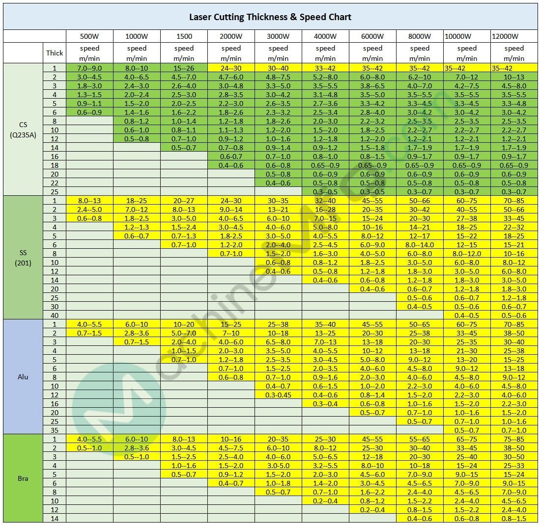
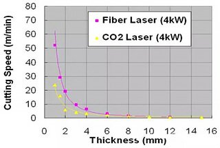
Fiber Laser Cutting Thickness & Speed Chart
The following laser cutting thickness chart might be helpful for you.
You can also download the xls file of laser cutting thickness chart on this page.
As the founder of MachineMFG, I have dedicated over a decade of my career to the metalworking industry. My extensive experience has allowed me to become an expert in the fields of sheet metal fabrication, machining, mechanical engineering, and machine tools for metals. I am constantly thinking, reading, and writing about these subjects, constantly striving to stay at the forefront of my field. Let my knowledge and expertise be an asset to your business.
Choosing the right high-power fiber laser for your industrial needs can be a daunting task. Does higher power always mean better efficiency? Not necessarily. This guide explores common misconceptions and…
Imagine a tool so precise it can cut through metal with the finesse of a surgeon's scalpel. Fiber lasers have revolutionized industries from manufacturing to medicine. This article delves into…
Have you ever wondered how cutting-edge technology achieves such precision? Fiber lasers, a marvel of modern engineering, utilize rare-earth doped glass fibers to generate highly efficient and versatile laser beams.…
What causes laser cutting heads to fail, and how can you prevent it? This article delves into common contamination issues affecting fiber laser cutting head lenses and offers practical solutions…
Have you ever struggled to achieve the perfect cut on metal? In this blog post, we'll uncover the secrets to optimal cutting parameters for various metals using a 3000W fiber…
Imagine cutting through metal as effortlessly as slicing through butter. Fiber laser technology has revolutionized metalworking, offering unmatched precision and speed. This article explores the cutting speeds of various metals…
How fast can a fiber laser cut different metals? If you've ever wondered about optimizing cutting speeds for materials like carbon steel or aluminum, this article offers detailed speed charts…
Have you ever wondered how a laser can cut through metal like a hot knife through butter? In this fascinating article, we'll explore the science behind fiber laser cutting technology.…
Have you ever wondered which laser cutting technology truly reigns supreme? This article dives into the battle between fiber lasers and CO2 lasers, exploring their strengths, weaknesses, and the factors…