This article mainly introduces several mature special processing methods.
I. Electrical Discharge Machining (EDM)
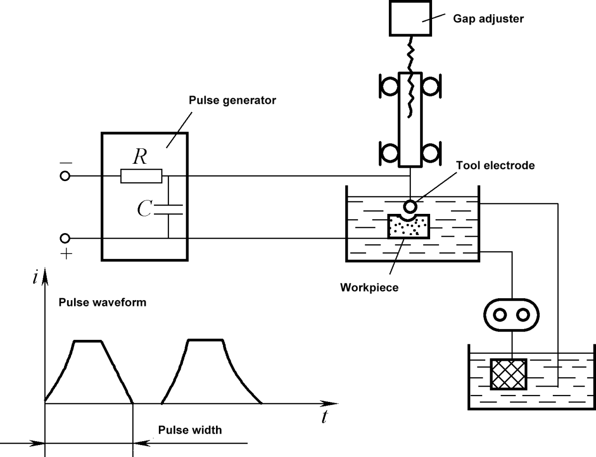
Figure 8-41: Schematic Diagram of the Principle of Electrical Discharge Machining
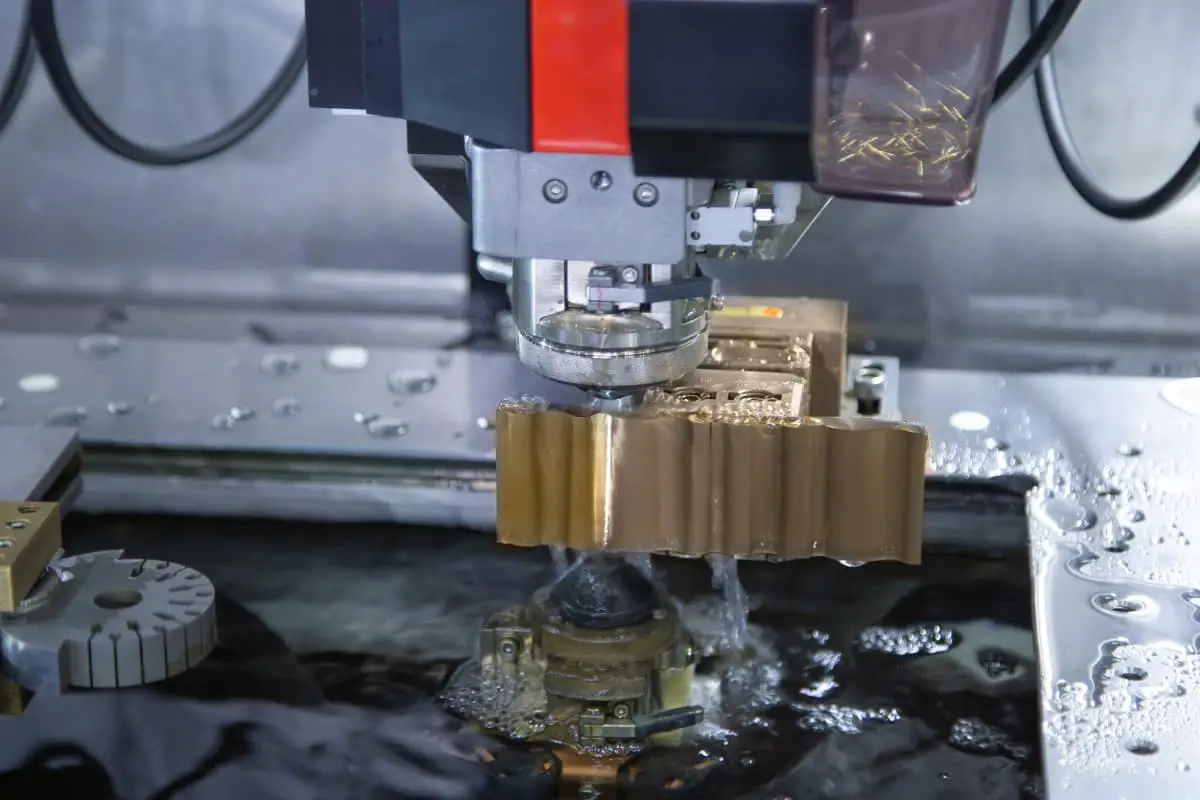
EDM is a method of machining conductive materials by utilizing the phenomenon of electrical corrosion during pulse discharge between positive and negative electrodes in a certain liquid medium. This results in the dimensions, shape, and surface quality of the parts meeting technical requirements. It is also known as discharge machining or electro-erosion machining. The working principle is shown in Figure 8-41.
During EDM, the workpiece and the tool (made of pure copper or graphite), which are charged with pulse voltage, act as positive and negative electrodes respectively. When they are close in the insulating working fluid (kerosene or mineral oil), the inter-electrode voltage will break down at the closest point between the two electrodes, forming a pulse discharge.
The high temperature generated in the discharge channel causes the metal to melt and vaporize, and the melted metal is thrown out under the effect of discharge explosion force and carried away by the insulating working fluid.
Due to the polar effect (i.e., the unequal erosion amounts of the two electrodes), the erosion speed of the workpiece electrode is much greater than that of the tool electrode. Thus, during the electro-erosion process, if the tool electrode is continuously fed into the workpiece, the machining of the workpiece can be accurately completed according to the shape of the tool.
(1) Process Features of EDM
1) It can process any hard, brittle, tough, and high melting point conductive materials, such as hard alloys, hardened steel, and stainless steel.
2) There is no significant mechanical force during processing, which is beneficial for machining small holes, thin walls, and parts with various complex cross-sectional shapes and cavities.
3) Pulse parameters can be adjusted, allowing for rough and fine machining on the same machine.
4) The machining size accuracy can reach 0.01mm, and the surface roughness Ra value is 0.8μm. For micro-precision machining, the size accuracy can reach 0.04~0.002mm, and the surface roughness Ra value is 0.1~0.05μm.
5) EDM has a slow processing speed, and the tool electrode suffers from wear, affecting the processing efficiency and forming accuracy.
(2) Applications of EDM
EDM is used for machining various cross-sectional shapes of shaped holes, small holes; machining various forging molds, extrusion molds, die-casting molds and other shaped cavities, integral impellers, blades and various curved surface parts; surface strengthening and engraving; and for electrical discharge wire cutting processing.
II. Electrochemical Machining (ECM)
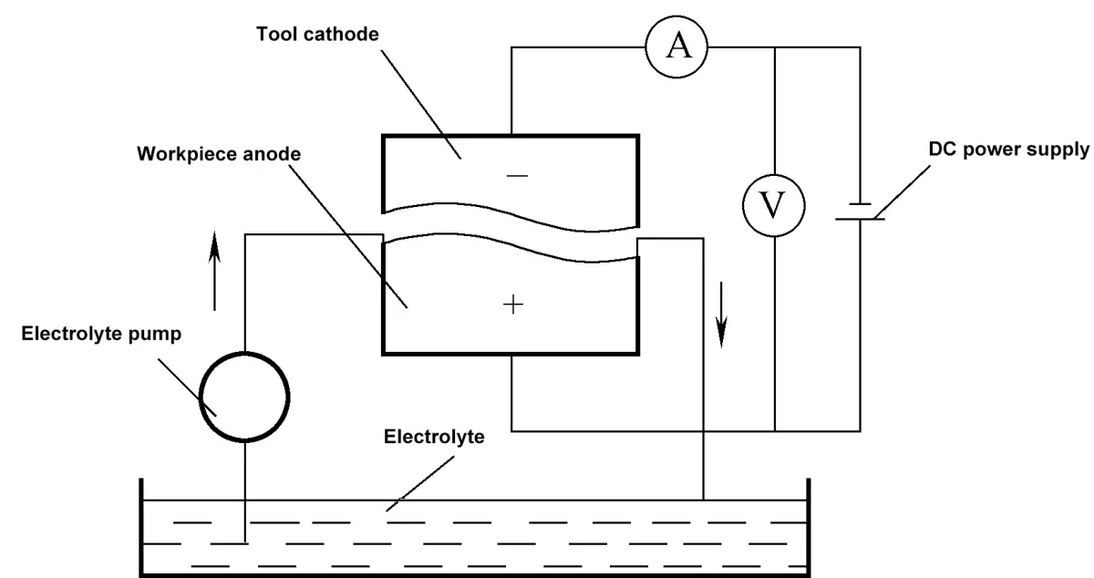
Figure 8-42 Schematic Diagram of Electrolytic Machining Principle
ECM is a method of shaping a workpiece by using the principle of an electrochemical reaction, where the metal dissolves as an anode in the electrolyte. As illustrated in Figure 8-42, during ECM, the workpiece is connected to the positive terminal, and the tool electrode to the negative terminal, with a low voltage, high current passing between them.
A high-speed electrolyte is injected into the narrow gap between the two terminals. As the tool electrode continuously feeds into the workpiece, the material of the workpiece dissolves in the shape of the tool surface due to the anodic dissolution of the metal in the electrolyte. The electrolysis products are then removed by the high-speed electrolyte flow, hence creating a shape on the workpiece that corresponds to the tool surface.
(1) ECM Process Features
1) It can machine high-hardness, high-strength, and high-toughness metals like hardened steel, hard alloy, and stainless steel, with high production rates.
2) There are no cutting forces or cutting heat, making it suitable for machining easily deformable parts (like thin-walled parts).
3) The average machining accuracy can reach 0.03~0.05mm, and the surface roughness Ra value can reach 1.6~0.2μm, with no residual stress.
4) In theory, the tool cathode does not wear out during the process, allowing for long-term use.
5) The electrolyte corrodes the machine tool, and the electrolysis products are difficult to treat and recycle.
(2) ECM Applications
ECM is widely used for deep hole drilling, hole enlargement, spline hole drilling, small-sized and intricately shaped hole drilling, low-precision cavity mold processing, irregular part blanking, deburring, and electrochemical chamfering.
III. Ultrasonic Machining (USM)
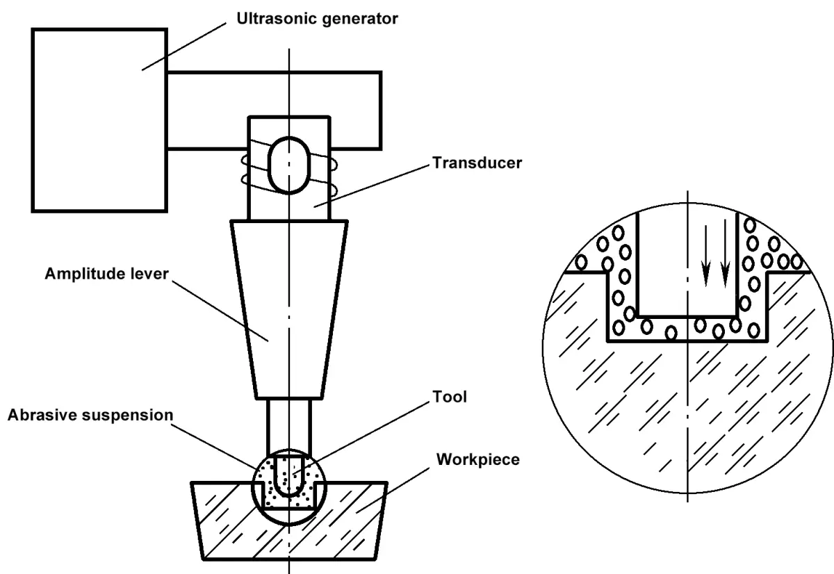
Figure 8-43 Schematic Diagram of Ultrasonic Machining Principle
USM is a method of machining a workpiece using high-frequency vibrations on the tool face and abrasive slurry. As shown in Figure 8-43, the ultrasonic generator creates high-frequency electrical oscillations that are transformed into small amplitude ultrasonic mechanical vibrations by the transducer. The amplitude is then amplified to 0.01~0.15mm by the amplitude rod and transferred to the tool to cause it to vibrate.
Meanwhile, the abrasive slurry is continuously injected between the workpiece and the tool. The ultrasonically vibrating tool face continuously hammers the abrasive on the workpiece surface, pulverizing the material in the machining area into fine particles that are removed by the circulating abrasive slurry. The tool gradually enters the workpiece, replicating its shape on the workpiece.
(1) USM Process Features
1) It is suitable for machining various non-conductive hard, brittle materials, such as glass, ceramics, gemstones, and diamond.
2) It is easy to machine various complex shapes of holes, cavities, and forming surfaces, and with a hollow-shaped tool, various shapes of blanking can also be achieved.
3) The cutting force and thermal effect are small, making it suitable for machining thin-walled, narrow gap, and other low-rigidity workpieces.
4) Ordinary USM equipment is simple.
5) The accuracy can reach 0.05~0.01mm, and the surface roughness Ra value can reach 0.8~0.1μm, but the production rate is relatively low.
(2) USM Applications
USM is suitable for machining thin-walled, narrow gap, thin sheet parts; it is widely used for hole drilling, blanking, cutting, and engraving of hard, brittle materials, and machining of diamond wire drawing dies; in combination with other machining methods, it can also perform composite machining.
IV. Laser Machining
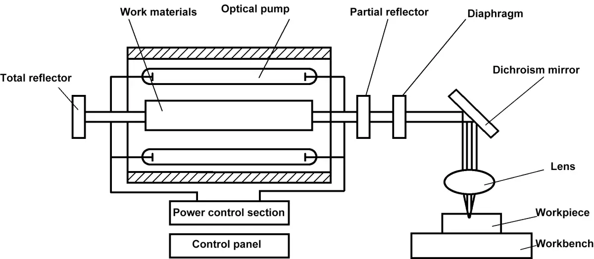
Figure 8-44 Schematic Diagram of Laser Generation and Working Principle
Laser machining is a method of machining where a laser, a coherent light with good monochromaticity, strong directionality, and excellent focusing performance, is used. After focusing, the power density reaches 108~1012W/cm2, and the temperature reaches over 10,000℃.
The laser irradiates the material being machined, causing it to instantaneously melt and even vaporize, and strong shock waves are generated, explosively removing the material. The working principle of laser machining is shown in Figure 8-44.
(1) Laser Machining Process Features
1) Laser machining has a short action time, small heat-affected zone, is not affected by electromagnetic interference, and can almost process all metal and non-metal materials.
2) The machining speed is extremely high, easy to realize automated production and assembly line operations, and thermal deformation is also very small.
3) The process does not require the use of tools and is a non-contact machining method, with no mechanical processing deformation.
4) It can process through air, inert gases, or optically transparent media.
5) The machining accuracy can reach 0.01mm, and the surface roughness Ra value can reach 0.1μm.
(2) Laser Machining Applications
1) Laser machining is mostly used for small hole machining in materials such as diamond wire drawing dies, clock and jewelry bearings, ceramics, glass, hard alloys, and stainless steel. The hole diameter is generally 0.01~1mm, and the smallest hole diameter can reach 0.001mm; the depth-to-diameter ratio of the hole can reach 50~100.
2) Laser machining is used for cutting, and the material thickness can reach several tens of millimeters. It can also cut the filament inside a vacuum tube through glass. It can weld through glass, which is difficult to accomplish with any other mechanical machining. By scanning the surface of the workpiece material with a laser, surface heat treatment of the material can be carried out, such as laser hardening of the surface of low carbon steel.
As the founder of MachineMFG, I have dedicated over a decade of my career to the metalworking industry. My extensive experience has allowed me to become an expert in the fields of sheet metal fabrication, machining, mechanical engineering, and machine tools for metals. I am constantly thinking, reading, and writing about these subjects, constantly striving to stay at the forefront of my field. Let my knowledge and expertise be an asset to your business.
Basic Concepts of Computer-Aided Design and Computer-Aided Manufacturing Computer-aided design and computer-aided manufacturing (CAD/CAM) is a comprehensive and technically complex system engineering discipline that incorporates diverse fields such as computer [...]
Concept of Virtual Manufacturing Virtual Manufacturing (VM) is the fundamental realization of the actual manufacturing process on a computer. It utilizes computer simulation and virtual reality technologies, supported by high-performance [...]
A Flexible Manufacturing System (FMS) typically employs principles of systems engineering and group technology. It connects Computer Numerical Control (CNC) machine tools (processing centers), coordinate measuring machines, material transport systems, [...]
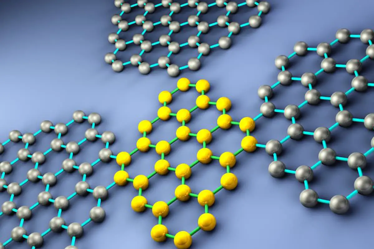
Just as manufacturing technology plays a crucial role in various fields today, nanofabrication technology holds a key position in the realms of nanotechnology. Nanofabrication technology encompasses numerous methods including mechanical [...]
Ultra-precision machining refers to precision manufacturing processes that achieve extremely high levels of accuracy and surface quality. Its definition is relative, changing with technological advancements. Currently, this technique can achieve [...]
Currently, machining can be categorized into two groups based on production batch: Among these two categories, the first one accounts for about 70-80% of the total output value of machining [...]
This article mainly introduces several mature special processing methods. I. Electrical Discharge Machining (EDM) EDM is a method of machining conductive materials by utilizing the phenomenon of electrical corrosion during [...]
What is CNC machining? Numerical Control (NC) refers to the method of controlling the movement and processing operations of machine tools using digitized information. Numerical Control Machine Tools, often abbreviated [...]
Cutting machining remains the most prominent method of mechanical processing, holding a significant role in mechanical manufacturing. With the advancement of manufacturing technology, cutting machining technology underwent substantial progress towards [...]
1. What is welding stress Welding stress refers to the stress generated during the welding process in welded components. This stress is caused by the thermal process of welding and [...]
Advanced materials refer to those recently researched or under development that possess exceptional performance and special functionalities. These materials are of paramount significance to the advancement of science and technology, [...]
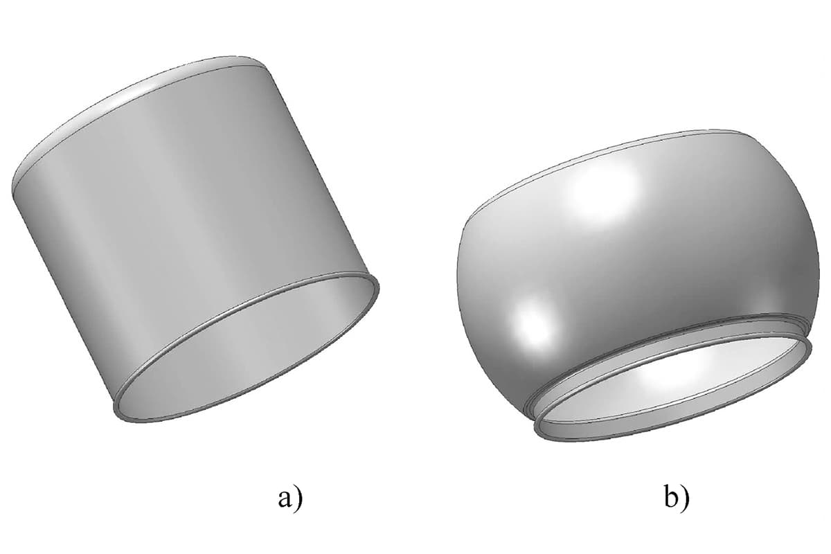
Bulge forming is suitable for various types of blanks, such as deep-drawn cups, cut tubes, and rolled conical weldments. Classification by bulge forming medium Bulge forming methods can be categorized [...]