9 Must-Knows About Low-Voltage Electrical Apparatus
Ever wondered what keeps your home’s electrical systems safe and reliable? Low-voltage electrical apparatus, like circuit breakers and contactors, play a crucial role in ensuring this. This article demystifies the various types and functions of these devices, detailing how they protect against overloads and short circuits, and providing guidelines for their selection and use. By reading further, you’ll gain valuable insights into maintaining a secure and efficient electrical system in your household or workplace.
A low voltage circuit breaker, also known as an automatic switch or air switch, is used for infrequent on-off control in low-voltage distribution circuits. It can automatically disconnect a faulty circuit in the event of a short circuit, overload, or undervoltage and serves as a control and protection device.
There are several types of circuit breakers, including DW frame, DZ plastic shell, DS DC fast, DWX, and DWZ current limiting circuit breakers. Each type is differentiated based on its intended use and structural characteristics.
The DW frame circuit breaker is primarily used to protect distribution lines, while the DZ plastic shell circuit breaker can be used for both protection and control of distribution lines, as well as for motor, lighting, and electrothermal circuits.
This article will provide a brief overview of the structure, working principle, use, and selection method of the molded case circuit breaker as an example.
Structure and operation of circuit breaker
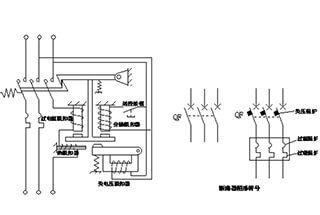
The circuit breaker is primarily composed of three key components: contacts, an arc extinguishing system, and various releases including overcurrent, voltage loss (undervoltage), thermal, shunt, and free releases.
The schematic diagram in Figure 1-8 illustrates the working principle of the circuit breaker, including its graphical symbols.
The operating mechanism can manually or electrically close the breaker switch. Once the contacts are closed, the free tripping mechanism secures them in the closed position.
The overcurrent release serves to protect the line from short circuits and overcurrents. If the current in the line exceeds the set value, the overcurrent release generates an electromagnetic force, causing the hook to trip and the moving contact to quickly disconnect under the tension of the spring. This action enables the tripping function of the short circuit release.
Fig. 1-8 schematic diagram and graphic symbols of circuit breaker working principle
The thermal release is utilized for line overload protection and operates on the same principle as a thermal relay.
The voltage loss (undervoltage) release provides protection against voltage loss.
As depicted in Figure 1-8, the coil of the voltage loss release is connected directly to the power source and is in the “pull in” state, allowing for normal circuit breaker closure.
In the event of a power failure or low voltage, the attraction force of the voltage loss release becomes weaker than the spring reaction force, causing the spring to push the moving iron core upward and trip the hook, thereby tripping the circuit breaker.
The shunt release is used for remote tripping and is activated by pressing a remote button, which powers the release and generates electromagnetic force to trip.
The appropriate circuit breaker protection should be selected based on the specific needs, and this information can also be indicated in the graphic symbol as shown in Figure 1-8.
The graphic symbol of the circuit breaker displays three protection modes: voltage loss, overload, and overcurrent.
Selection principle of low voltage circuit breaker
When selecting a low-voltage circuit breaker, the following factors should be considered:
Circuit breaker type selection: The circuit breaker should be selected based on the application and protection requirements.
For general use, a plastic shell type may be selected.
For large short-circuit currents, a current-limiting type should be selected.
For high rated currents or selective protection requirements, a frame type should be chosen.
For DC circuits containing semiconductor devices, a DC fast circuit breaker should be used.
Rated voltage and current: The rated voltage and current of the circuit breaker must be equal to or greater than the normal working voltage and current of the line and equipment.
Making and breaking capacity: The limit making and breaking capacity of the circuit breaker must be equal to or greater than the maximum short-circuit current of the circuit.
Undervoltage release: The rated voltage of the undervoltage release should be equal to the rated voltage of the line.
Overcurrent release: The rated current of the overcurrent release should be equal to or greater than the maximum load current of the line.
Controller
The Controller is a manual operation device that directly controls high currents (ranging from 10A to 600A) in the main circuit. Some common types of controllers include the KT Type Cam Controller, the KG Type Drum Controller, and the KP Type Plane Controller.
The functions and operating principles of these controllers are generally similar. Taking the Cam Controller as an example, it is a large-scale manual controller that is primarily used to control the start, stop, speed regulation, commutation, and braking of small to medium-sized wound asynchronous motors in hoisting equipment. It is also suitable for other applications that have similar requirements.
The Cam Controller consists of contacts, a rotating shaft, a cam, a lever, a handle, an arc extinguishing cover, and a positioning mechanism. The structural principle diagram and graphical symbols of the Cam Controller are shown in Figure 1-9.
The Cam Controller has multiple groups of contacts that are controlled by multiple cams, allowing for the simultaneous control of multiple contacts in complex circuits. Since there are many contacts in the Cam Controller, each connection at each position is different, and cannot be represented by normal open and closed contacts.
Figure 1-9 (a) shows the schematic diagram of a 1-pole 12 position Cam Controller. The graphical symbol in Figure 1-9 (b) indicates that there are 12 positions for this contact, and the small black dot in the figure represents that the position contact is connected. As seen from the schematic diagram, when the handle is turned to positions 2, 3, 4, and 10, the contact is connected by the cam.
Figure 1-9 (c) shows a 5-pole 12 position Cam Controller, which is comprised of five 1-pole 12 position Cam Controllers. Figure 1-9 (d) shows the graphical symbol of a 4-pole 5-bit Cam Controller, indicating that there are 4 contacts, each with 5 positions. The small black dot in the figure represents that the contact is connected at this position. For example, when the handle is turned to position 1 on the right, contacts 2 and 4 are connected.
The Cam Controller has a large contact capacity and an arc extinguishing device, as it can directly control the motor. Its advantages include a simple control circuit, few switching elements, and easy maintenance. However, it also has some disadvantages, such as its large size, heavy operation, and inability to be remotely controlled.
Some of the Cam Controllers currently in use include the KT10, KTJL4, KTJL5, and KTJL6 series.
Fig. 1-9 structural principle diagram and graphic symbols of cam controller
Contactor
Contactors are commonly used to control motors, electric heating equipment, electric welding machines, capacitor banks, and other electrical devices. They can switch the AC and DC main circuits on and off frequently to enable remote automatic control.
Contactors have a low voltage release protection function and are widely used in the automatic control circuits of electric drives. There are two types of contactors: AC Contactors and DC Contactors. The following description focuses on AC Contactors.
Figure 1-10 shows the structural diagram and graphical symbols of AC contactor.
Components of AC contactor
Electromagnetic Mechanism
The Electromagnetic Mechanism is comprised of a coil, a moving core (armature), and a static core.
Contact System
The contact system of an AC contactor consists of a main contact and an auxiliary contact.
The main contact is utilized to make and break the primary circuit and typically has three or four pairs of normally open contacts.
The auxiliary contact serves the purpose of controlling the circuit and acts as an electrical interlock or control. It usually has two pairs of normally open and two pairs of normally closed contacts.
Arc Extinguishing Device
All contactors with a capacity of more than 10A have an arc extinguishing device.
For contactors with small capacity, double break bridge contacts are frequently employed to aid in arc extinguishing.
For large capacity contactors, a longitudinal seam arc extinguishing cover and grid arc extinguishing structure are often utilized.
Other Parts
The other parts include a reaction spring, a buffer spring, a contact pressure spring, a transmission mechanism, and a shell, among others.
The contactor is marked with a terminal number, with the coils being designated as A1 and A2. The main contacts 1, 3, and 5 are connected to the power side, while 2, 4, and 6 are connected to the load side.
The auxiliary contact is represented by two digits, where the first digit represents the sequence number of the auxiliary contact, and the last digit (3 and 4) represents the normally open contact, while 1 and 2 represent the normally closed contact.
The control principle of the contactor is straightforward.
When the coil is supplied with the rated voltage, an electromagnetic force is generated that overcomes the spring reaction force, causing the moving iron core to move downward.
The downward movement of the moving iron core drives the insulating connecting rod and moving contact downward, thereby closing the normally open contact and disconnecting the normally closed contact.
When the coil loses power or the voltage drops below the release voltage, the electromagnetic force becomes weaker than the spring reaction force, causing the normally open contact to disconnect and the normally closed contact to close.
Main technical parameters and types of contactors
Rated Voltage
The rated voltage of a contactor refers to the rated voltage of its main contact.
In AC systems, the rated voltage can range from 220V to 1140V in special circumstances, with common ratings being 380V and 660V. In DC systems, the most common rated voltages are 110V, 220V, and 440V.
Rated Current
The rated current of a contactor refers to the maximum current that its main contact can handle while operating under specified conditions, such as rated voltage, service category, and operating frequency.
At present, the commonly used current ratings range from 10A to 800A.
Rated voltage of suction coil
AC 36V, 127V, 220V and 380V, DC 24V, 48V, 220V and 440V.
Mechanical life and electrical life
Contactors are electrical appliances that are frequently used and should have a high mechanical and electrical lifespan, which is an important indicator of product quality.
Rated operating frequency
The rated operating frequency of a contactor refers to the maximum number of allowed operations per hour, typically 300 operations per hour, 600 operations per hour, or 1200 operations per hour.
Action value
The action value refers to the pull-in voltage and release voltage of the contactor.
It is specified that the contactor must reliably pull in when the pull-in voltage is greater than 85% of the rated voltage of the coil, and the release voltage must not be higher than 70% of the rated voltage of the coil.
Common AC Contactors
There are several common types of AC contactors, including the cjl0, cjl2, cj10x, cj20, cjxl, CJX2, 3TB, and 3td series.
Selection of contactor
(1) Choose the appropriate type of contactor based on the characteristics of the load.
(2) The rated voltage must be equal to or greater than the operating voltage of the main circuit.
(3) The rated current must be equal to or greater than the rated current of the controlled circuit.
(4) The motor load must be adjusted as necessary based on its operating mode.
(5) The rated voltage and frequency of the coil must match the selected voltage and frequency of the control circuit.
Starter
A starter is a complete set of low-voltage control device used for the starting and stopping control of a three-phase asynchronous motor.
The QJ type decompression starter employs an autotransformer to decrease voltage and is utilized for infrequent decompression starting control of a three-phase cage asynchronous motor.
The QX starter, on the other hand, is a star delta step-down starter.
The control circuits for various starters vary based on the model and capacity of the motor.
Master appliance
The master electrical appliance is a device used to control the switch contacts in a control circuit, enabling it to perform the necessary control tasks.
This appliance is widely used and comes in a variety of forms, including buttons, limit switches, proximity switches, universal transfer switches, master controllers, selector switches, and foot switches.
Button
Button is a widely used control device with a simple structure and ease of operation.
Structure, Types, and Common Models of Buttons
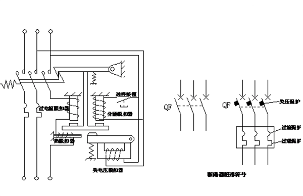
The button is composed of a button cap, a return spring, a bridge contact, and a shell. Its structure is depicted in Figure 1-20, along with its graphic symbol.
The contacts in the button are bridge contacts with a rated current of less than 5A.
Contacts are further classified into normally open contacts (dynamic breaking contacts) and normally closed contacts (dynamic closing contacts).
Buttons can be categorized based on their shape and mode of operation into flat buttons and emergency stop buttons.
The emergency stop button, also known as the mushroom head button, is depicted in Figure 1-20 (c).
Additionally, buttons come in various types such as key buttons, knobs, pull buttons, universal lever types, illuminated types, and more.
Figure 1-20 schematic diagram of button structure and graphic symbols
The mode of contact action in buttons can be divided into two types: direct action and micro action.
The buttons shown in Figure 1-20 are of the direct action type, and the speed of contact action is related to the speed at which the button is pressed.
The contact action transformation speed of an inching button is fast, and it is not related to the speed at which the button is pressed. The action principle is depicted in Figure 1-21.
The moving contact in the button consists of a deformed reed. When the curved reed is pressed downward and falls below the flat reed, it rapidly deforms and bounces the flat reed contact upward, resulting in instantaneous contact action.
A small micro button is also known as a micro switch.
Micro switches can be utilized in various relays and limit switches, such as time relays, pressure relays, and limit switches.
Fig. 1-21 action principle diagram of inching button
Buttons are typically reset and self-locking.
The most widely used button is the reset flat button, depicted in Figure 1-20 (a).
The button is designed to be flush with the shell to prevent accidental touch by foreign objects.
Button color
The red button is designated for functions such as “stop,” “power off,” and “emergency.”
Green buttons are preferred for “start” or “power on” functions, but buttons in black, white, or gray are also acceptable.
If a button serves dual purposes, such as “start” and “stop” or “power on” and “power off,” it should not be red or green but rather black, white, or gray.
For buttons that activate when pressed and deactivate when released (e.g. “inching” buttons), black, white, gray, or green buttons are acceptable, with black buttons being the preferred option.
The blue, black, white, or gray buttons should be used for single reset functions.
Red buttons should be reserved for those with functions such as “reset,” “stop,” and “power off.”
The light button should not be used for the purpose of an “emergency” button.
Selection principle of buttons
(1) Choose the appropriate control button based on the application, such as open type, waterproof type, anti-corrosion type, etc.
(2) Based on the intended use, select the appropriate button type, such as key type, emergency type, lamp type, etc.
(3) Determine the number of buttons required for the control circuit, including options such as single button, double button, three button, and multi-button.
(4) Select the color of the buttons and indicator lights based on the requirements for indicating the working status and conditions.
Table 1-1 gives the meaning of button color.
Colour
Meaning
An example
Red
Handling accidents
Emergency stop
Extinguish combustion
Stop or “power off”
Normal shutdown
Stop one or more motors
Local shutdown of the unit
Cut off a reset switch with “stop” or “power off” function
Green
Start or “power on”
Normal start
Start one or more motors
Local start of the device
Turn on a switching device (put into operation)
Yellow
Participate in
Prevent accidents
The parameter suppresses the abnormal state
Avoid unwanted changes (accidents)
Blue
Any specified intention not included in the above color
All meanings not included in red, yellow and green: blue can be used
Black, grey, white
No specific intention
Any function other than the “stop” or “power off” button of single function
Travel switch
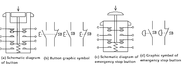
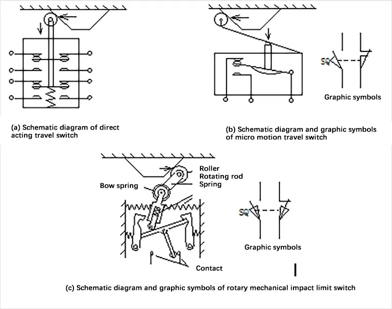
A travel switch, also known as a limit switch, has various types. It can be classified into direct action type, micro motion type, and rotary type based on its movement form, and into contact type and contactless type based on the nature of the contact.
The travel switch with contact is simply referred to as the travel switch. Its working principle is similar to that of a button, except that it is activated by the contact action of the moving parts of production machinery, instead of being pressed by hand. This switch is used to control the direction, speed, stroke size, or position of production machinery, and its structure can take many forms.
The action principle diagram and graphical symbols of various operation types of travel switches are shown in Figure 1-22. The main parameters of a travel switch include its type, action travel, working voltage, and current capacity of contact.
Currently, popular domestic travel switch brands include lxk3, 3se3, lxl9, LXW, and LX series. The commonly used travel switches are the LX19, LXW5, lxk3, lx32, and lx33 series.
Figure 1-22 structural diagram and graphic symbols of travel switch
Contactless Travel Switch
The Contactless Travel Switch, also referred to as a Proximity Switch, serves as a replacement for the traditional contact travel switch and provides travel control and limit protection.
In addition to its use in travel control, it can also be employed in various applications such as high-frequency counting, speed measurement, liquid level control, part size detection, and automatic connection in machining programs.
Due to its non-contact trigger, fast action speed, flexible detection distance, stable and reliable signal, long service life, high repeated positioning accuracy, and ability to function in harsh working environments, the Contactless Travel Switch is widely used in industries such as machine tools, textiles, printing, and plastics.
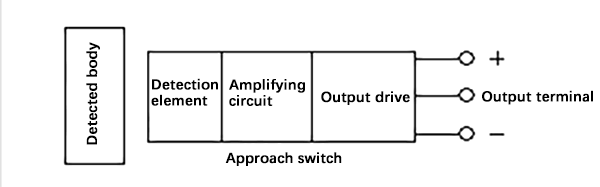
There are two main types of Contactless Travel Switches: active and passive. The majority of Contactless Travel Switches are active, consisting of a detection element, amplification circuit, and output driving circuit, and typically operate on 5V to 24V DC current or 220V AC power.
Figure 1-23 presents a structural block diagram of a three-wire active proximity switch.
Figure 1-23 structural block diagram of active proximity switch
Proximity switches can be classified into several types based on their working principle, including high-frequency oscillation, ultrasonic, capacitance, electromagnetic induction, permanent magnet, Hall element, and magnetic sensor types.
Each type of proximity switch has the ability to detect different objects. The capacitive proximity switch, for instance, can detect solid, liquid, or powder objects. It is made up of a capacitive oscillator and an electronic circuit, with its capacitance located at the sensing interface. When an object approaches, it causes a change in capacitance value, leading to an output signal.
The Hall proximity switch, on the other hand, is designed to detect magnetic fields. It is commonly used with magnetic steel as the detected body and has an internal magnetic sensitive device that is only sensitive to magnetic fields perpendicular to the end face of the sensor. When a magnetic pole (North or South) faces the proximity switch, the switch’s output will either be high level or low level.
The ultrasonic proximity switch is ideal for detecting objects that are difficult to access. It is not affected by acoustic, electrical, optical, or other factors, and can detect solid, liquid, or powder objects as long as they can reflect ultrasonic waves. The switch is comprised of a piezoelectric ceramic sensor, an electronic device for transmitting and receiving ultrasonic waves, and a program-controlled bridge switch for adjusting the detection range.
The high-frequency oscillating proximity switch is used for detecting various metals. It consists of a high-frequency oscillator, an integrated circuit or transistor amplifier, and an output. Its working principle is that when a metal object approaches the oscillator coil, it generates eddy currents that absorb the oscillator’s energy, causing the oscillator to stop. The oscillation and stop signals are then shaped and amplified into switching signals, which form the output.
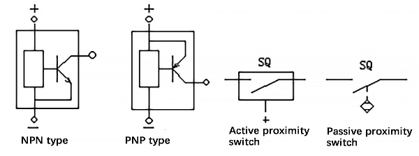
Proximity switches have various output forms, including two-wire, three-wire, and four-wire, and their transistor outputs can be NPN or PNP. They come in different shapes, including square, round, slot, and separated.
Figure 1-24 illustrates the working principle of a slot three-wire NPN photoelectric proximity switch and the working diagram of a remote separation photoelectric switch.
Figure 1-24 slot type and separate type photoelectric switch
The key features of a proximity switch include its type, range of action distance, action frequency, response time, repetition accuracy, output type, operating voltage, and output contact capacity.
The graphical representation of the proximity switch can be seen in Figure 1-25.
Figure 1-25 graphical symbols of proximity switch
There are various types of proximity switches, including the commonly used domestic switches such as the LJ, 3sg, and lxj18 series. Imported proximity switches are also widely used in China.
Selection of Contact Travel Switch
When selecting a contact travel switch, the following factors should be considered:
The application and the control object.
The installation environment, such as open or protective type.
The voltage and current of the control circuit.
The appropriate head form, based on the force transmission and displacement relationship between the machinery and the travel switch.
Selection of Proximity Switch
Operating frequency, reliability, and accuracy.
Inspection distance and installation dimensions.
Contact form (with or without contact), number of contacts, and output form (NPN or PNP type).
Power type (DC or AC) and voltage level.
Transfer switch
The Transfer Switch is a versatile electrical device with multiple gears, contacts, and loop controls. It serves a variety of purposes, including line replacement, remote control, and measurement of ammeter and voltmeter in control equipment. Additionally, it can be utilized to control the starting, switching, and speed regulation of small-capacity motors.
The operating principle of the Transfer Switch is similar to that of a Cam Controller, but the two are used in different applications. The Cam Controller is primarily used to directly control electrical equipment such as motors in the main circuit, while the Transfer Switch is mainly used in the control circuit to indirectly control electric machines through relays and contactors.
There are two main types of Transfer Switches commonly used: the Universal Transfer Switch and the Combination Switch. Both have similar structures and operating principles and can be interchangeable in some applications.
The Transfer Switch is further classified into three types based on its structure: ordinary, open combination, and protection combination. According to its purpose, it is divided into two categories: main command control and motor control.
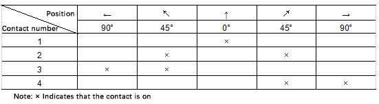
The graphic symbols used to represent the Transfer Switch are the same as those for the Cam Controller, as shown in Figure 1-26. The on-off state of the Transfer Switch contact is depicted in Table 1-2.
The key specifications of a transfer switch include the type, handle type, on/off state table for contacts, working voltage, number of contacts, and current capacity. These are explained in greater detail in the product manual.
Commonly used transfer switches include the LW2, LW5, LW6, LW8, LW9, LWL2, LWL6, VK, 3LB, and Hz series.
The LW2 series is used to control the operation circuit of high-voltage circuit breakers, while the LW5 and LW6 series are primarily utilized to control lines or motors in electrical drive systems. The LW6 series can also be installed in a double-column configuration, where the columns are meshed with gears and operated by a single handle.
The switch can be equipped with a maximum of 60 pairs of contacts.
When selecting a transfer switch, it is important to consider the following factors:
Rated voltage and operating current
Handle type and positioning
Number of contacts and wiring diagram
Panel type and marking.
Resistor
Resistance is a crucial electrical component found in various electrical products, and it can be classified into two types:
The first category is resistance components, which are utilized in electronic products with weak current. The second category is industrial resistance devices (commonly referred to as resistors), which are employed for regulating low-voltage, high-current AC and DC electrical lines, as well as controlling the starting, braking, and speed of motors.
The most widely used resistors are ZB plate and ZG tube resistors, which are utilized for regulating current in low-voltage circuits. The ZX resistor, on the other hand, is mainly used for starting, braking, and controlling the speed of AC and DC motors.
The key technical specifications of a resistor include its rated voltage, heating power, resistance value, allowable current, heating time constant, resistance error, and overall dimensions.
Figure 1-27 displays the graphical symbols for resistors.
Figure 1-27 graphical symbols of resistors and rheostats
Rheostat
The function of a rheostat is similar to that of a resistor, but with an important difference: while the resistance of a resistor is fixed, the resistance of a rheostat can be continuously adjusted. In control circuits, the resistance value can be adjusted by connecting resistors in series or parallel or by selecting different sections of resistance. The resistance value is then only adjustable in steps.
Common types of rheostats include BC sliding wire rheostats, which are used for regulating current and voltage in circuits and controlling or regulating electronic equipment and instruments. BL type excitation rheostats are used for regulating the excitation or speed of DC motors, BQ starting rheostats are used for starting DC motors, BT rheostats are used for regulating the excitation or speed of DC motors, and BP frequency-sensitive rheostats are used for starting control of three-phase AC wound asynchronous motors.
The main technical parameters of rheostats are similar to those of resistors. The graphic symbols for rheostats can be seen in Figure 1-27.
Voltage regulator
There are several types of voltage regulators. The TD4 carbon resistance voltage regulator is used to adjust the voltage automatically in small to medium-sized AC or DC generators.
Electromagnet
Electromagnets are widely used in various applications. Some of the commonly used types are the MQ traction electromagnet, MW lifting electromagnet, and MZ braking electromagnet.
The MQ traction electromagnet is used for controlling mechanical equipment and different automatic systems in low-voltage AC circuits. The MW lifting electromagnet is installed on lifting machinery to attract magnetic materials such as steel. The MZ single-phase and three-phase brake electromagnets are commonly used to form an electromagnetic brake.
The schematic diagram of the Tj2 AC electromagnetic brake, which is made up of a brake electromagnet, is shown in Figure 1-28. The electromagnetic brake and the motor shaft are typically installed together and connected in parallel. When both the electromagnetic brake coil and the motor coil are energized, the motor rotates. However, when power is lost, the brake shoe will hold the brake wheel tightly, stopping the motor with the help of a compression spring.
The graphic symbol of an electromagnet is the same as that of an electromagnetic brake and its text symbol is “YA.” The graphic symbols of electromagnetic brakes are shown in Figure 1-28.
Figure 1-28 schematic diagram and graphic symbols of electromagnetic brake
As the founder of MachineMFG, I have dedicated over a decade of my career to the metalworking industry. My extensive experience has allowed me to become an expert in the fields of sheet metal fabrication, machining, mechanical engineering, and machine tools for metals. I am constantly thinking, reading, and writing about these subjects, constantly striving to stay at the forefront of my field. Let my knowledge and expertise be an asset to your business.
Attention all mechanical engineers and manufacturing professionals! Are you struggling with pesky anodizing defects in your aluminum products? Look no further! In this blog post, we'll dive deep into the…
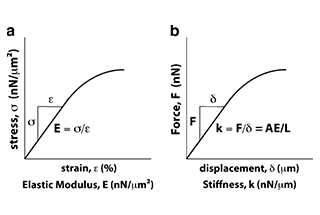
Ever wondered why some materials bend easily while others remain rigid? This blog dives into the fascinating world of elastic modulus and stiffness, unraveling their crucial roles in engineering. By…
Have you ever wondered what makes a perfect circle? In the world of mechanical engineering, roundness is a crucial concept that affects the performance and longevity of rotating components. This…
In today's fast-paced manufacturing world, efficient deburring is crucial. With numerous methods available, choosing the right one can be daunting. In this blog post, we'll explore various deburring techniques, from…
Have you ever wondered what keeps the world spinning smoothly? The unsung heroes behind the scenes are bearings. These small but mighty components play a crucial role in reducing friction…
Gears are the unsung heroes of the mechanical world, quietly working behind the scenes to keep machines running smoothly. But have you ever wondered what materials these critical components are…
This article explores the top 5 cooling tower manufacturers shaping our world. Learn how these companies innovate to keep industries running smoothly and efficiently. Get ready to uncover the secrets…
Have you ever wondered what keeps our gas systems running smoothly and safely? In this article, we explore top gas regulator manufacturers, uncovering their innovations and contributions to the industry.…
Ever wondered why connecting copper and aluminum wires is problematic? This article explains the risks associated with connecting these two metals due to their differing electrochemical properties, which can lead…