The Essential Guide to Dry Gas Seals: Structure & Function
Have you ever wondered how critical equipment in high-pressure environments maintains reliable operation? Dry gas seals are the unsung heroes that ensure smooth functioning and prevent leakage. In this article, we’ll dive into the world of dry gas seals, exploring their working principles, advantages, and applications. Our expert mechanical engineer will guide you through this fascinating technology, providing valuable insights and real-world examples. Get ready to discover how dry gas seals are revolutionizing various industries!
Dry gas sealing is a novel type of non-contact shaft seal developed from the basis of gas-lubricated bearings in the late 1960s, with spiral groove seals being the most typical example.
After years of research, the John Crane Company in the United States was the first to introduce dry gas seal products for industrial use.
Practice has shown that dry gas seals offer many advantages over conventional contact mechanical seals. They are primarily used in pipelines, offshore platforms, refineries, and the petrochemical industry, suitable for any gas transmission system.
As dry gas seals are non-contact seals not limited by PV value, they are especially suitable for large centrifugal compressors under high-speed and high-pressure conditions. The advent of dry gas seals represents a revolutionary advancement in sealing technology, solving the challenges of gas sealing without the limitations of seal lubricating oil.
Moreover, their required gas control systems are much simpler than the oil systems of film seals.
Additionally, the emergence of dry gas seals has changed traditional sealing concepts by organically integrating dry gas seal technology with barrier seal principles.
The new concept of “using gas as a sealant” replaces the traditional “liquid seals gas or liquid” concept, ensuring zero leakage of any sealing medium. This makes dry gas seals widely applicable in the field of pump shaft seals.
The following table compares the leakage rates of compressor dry gas seals with other common seals:
Sealing type
parameter
Leakage rate (Nm3/min)
Gas lubrication seal
Dry gas seal
Slot depth 5 µm
0.025
Carbon ring seal
Four groups, 10mm wide with a gap of 0.05mm
0.37
Labyrinth seal
Number of teeth 15
1.82
Oil film seal
Sealing oil leakage amount
Media end (L/min)
Atmospheric end (L/min)
Floating ring seal
2 groups, each 20mm wide, with a gap of 0.05mm
0.12
0.6
mechanical seal
Oil film thickness 1 µm
0.0012
0.0017
Test conditions for the experimental unit: shaft diameter of 140mm, speed of 5000rpm, process gas pressure of 0.6MPa, and seal oil (gas) pressure of 0.75MPa.
Compared to conventional contact mechanical seals, dry gas seals offer the following main advantages:
Elimination of the sealing oil system and the additional power load required to operate it.
Significant reduction in unplanned maintenance costs and production downtime.
Prevention of process gas contamination by oil.
Minimal leakage of sealing gas.
Low maintenance costs and good economic practicality.
Low power consumption for seal operation.
Long seal life and reliable operation.
II. Working Principle of Dry Gas Seals
Compared to other mechanical seals, dry gas seals are fundamentally similar in structure. The main difference is that one sealing ring of a dry gas seal has evenly distributed shallow grooves. These grooves allow the seal to operate in a non-contact state by generating a fluid dynamic pressure effect during rotation, separating the sealing surfaces.
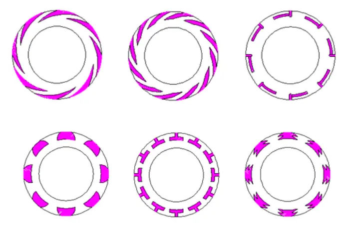
The groove shapes on the sealing end face of dry gas seals are mainly categorized into single-directional and bi-directional types.
Single-directional grooves are most commonly used in current compressor units. They can only be used in units with unidirectional rotation, generating opening force in the required direction; if reversed, negative opening force may damage the seal.
However, compared to the bi-directional grooves, they can generate greater opening forces and gas film rigidity, offering higher stability and more reliable prevention of end-face contact, thus usable at very low speeds and under significant vibration.
Bi-directional grooves are common as well. This groove type has no directional requirements, suitable for both forward and reverse rotations without damaging the seal. Its application range is broader than that of single-directional grooves, but its stability and interference resistance are inferior.
Through repeated experiments and comparative studies on various groove types of dry gas seals, it has been confirmed that the helical groove design offers the highest gas film rigidity with minimal leakage, achieving the best leakage ratio. Below is a detailed introduction to this groove type.
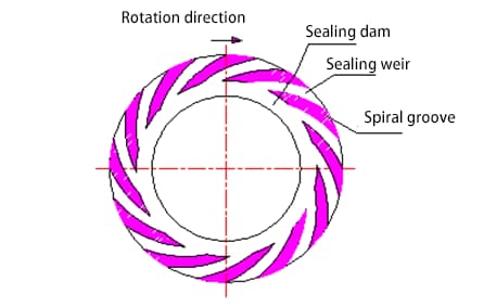
The diagram below illustrates a typical dry gas seal with helical grooves on the sealing surface, with a depth of less than 10 micrometers. When the seal operates, the sealed gas is tangentially drawn into the helical grooves, moving radially from the outer diameter towards the center (i.e., the low-pressure side), restricted by the sealing dam from flowing towards the low-pressure side.
The gas is compressed as it moves along the varying cross-sectional shape of the helical grooves, creating a localized high-pressure area at the groove root, separating the end faces by a few micrometers to form a gas film of certain thickness.
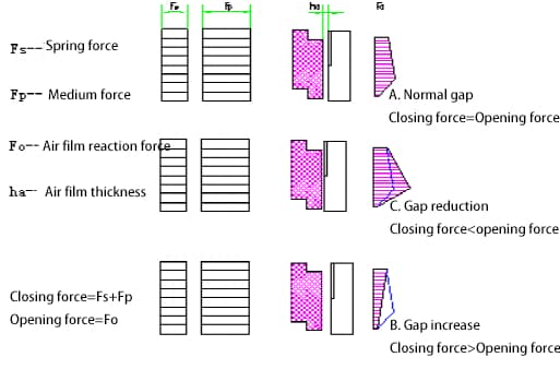
Under this gas film thickness, the opening force generated by the gas film action balances with the closing force generated by spring and medium forces, allowing the seal to operate non-contact. The gas film formed between the sealing surfaces of the dry gas seal has a certain positive stiffness, ensuring the stability of the seal operation. To obtain the necessary fluid dynamic pressure effect, the dynamic pressure grooves must be located on the high-pressure side.
The diagram above shows the forces acting on a helical groove dry gas seal, illustrating how gas film rigidity ensures the stability of seal operation. Under normal conditions, the seal’s closing force equals the opening force.
When external disturbances occur (e.g., process or operational fluctuations), leading to a decrease in gas film thickness, the gas’s viscous shear force increases, enhancing the fluid dynamic pressure effect generated by the helical grooves, thereby increasing the gas film pressure and opening force to maintain force balance and restore the seal to its original gap; conversely, if the seal is disturbed and the gas film thickness increases, the dynamic pressure effect generated by the helical grooves weakens, reducing the gas film pressure and opening force, allowing the seal to return to its original gap.
Therefore, as long as it is within the design range, when external disturbances are eliminated, the seal can always return to its designed working gap, meaning the dry gas seal has a self-adjusting function that ensures stable and reliable operation.
The main indicator of seal stability is the stiffness of the gas film generated, which is the ratio of the change in gas film force to the change in gas film thickness. The greater the gas film stiffness, the stronger the seal’s interference resistance and the more stable its operation.
III. Typical Dry Gas Seal Structures
There are different overall structural forms of dry gas seals suitable for various working conditions. In practice, the dry gas seals used in centrifugal compressors mainly include the following four structures:
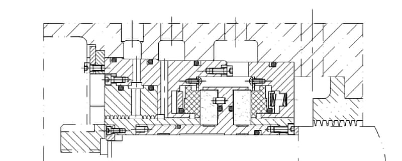
Single Face Seal
The single face seal is primarily used for non-hazardous gases, i.e., situations where minor leakage of the medium gas into the atmosphere is permissible. The gas used for sealing is the process gas itself. This type is commonly used in domestically imported units, such as carbon dioxide compressors.
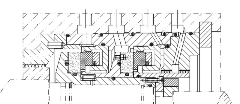
Tandem Seal
The tandem dry gas seal is a sealing structure with high operational reliability, typically applied where minor leakage of the medium gas into the atmosphere is permissible. It is widely used in the introduced units of petrochemical enterprises.
A tandem dry gas seal can be considered as two or more sets of dry gas seals connected in the same direction end-to-end. Similar to the single face structure, the sealing gas is the process gas itself. Typically, a two-stage structure is used where the first stage (primary seal) bears the full load, and the other stage serves as a backup seal without bearing pressure drop.
The process gas leaked from the primary seal is introduced to a flare for combustion. A very small amount of unburned process gas leaks through the secondary seal and is vented safely.
Should the primary seal fail, the secondary seal acts as an auxiliary safety seal, preventing massive leakage of the process medium into the atmosphere.
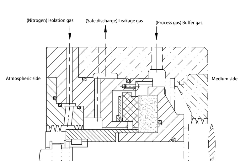
Tandem Seal with Intermediate Labyrinth
When leakage of the process medium into the atmosphere is not allowed, nor is leakage of buffer gas into the process medium, an intermediate labyrinth seal can be added between the two stages of a tandem structure.
This structure is used for flammable, explosive, and hazardous gases, achieving no external leakage. Examples include H2 compressors, natural gas compressors with high H2S content, ethylene, propylene, and ammonia compressors.
Besides the process gas, this structure also requires an additional nitrogen gas route as the sealing gas for the secondary seal. The process gas leaked from the primary seal is entirely introduced to a flare for combustion by nitrogen gas.
All gases leaked into the atmosphere through the secondary seal are nitrogen. Should the primary seal fail, the secondary seal also serves as an auxiliary safety seal. This structure is relatively complex, but due to its highest reliability, it has become the standard configuration in medium and high-pressure centrifugal compressor shaft seals.
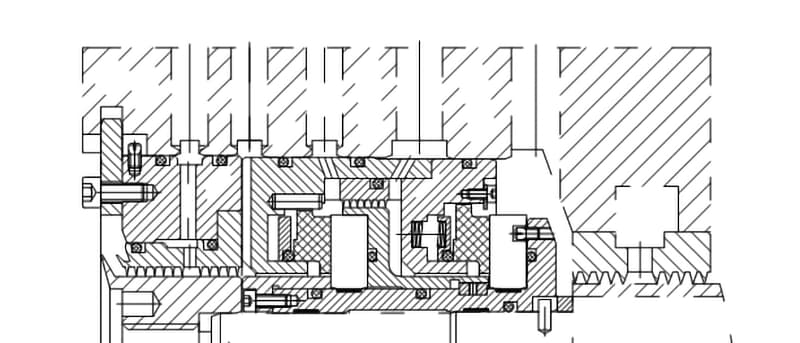
Double Face Seal
The double face seal is equivalent to two single face seals arranged face-to-face, sometimes sharing one rotating ring. It is suitable for conditions without flare systems, where minor leakage of sealing gas into the process medium is permissible. Introducing nitrogen gas between the two sets of seals forms a reliable blocking seal system.
The pressure of nitrogen gas is controlled to always maintain a level slightly higher than the process gas pressure (0.2-0.3MPa), ensuring that the direction of gas leakage is always towards the process medium and the atmosphere, thereby preventing the process gas from leaking into the atmosphere. The double face seal structure is mainly used for low-pressure toxic, flammable, and explosive gases.
IV. Dry Gas Seal Design Overview
Dry gas seals operate with non-contacting faces during operation, but brief contact occurs during start-up and shut-down phases, necessitating the use of wear-resistant materials for the mating surfaces.
The materials for the friction pairs in dry gas seals typically include materials with low thermal expansion coefficients, high elastic modulus, tensile strength, thermal conductivity, and hardness, such as SiC or cemented carbide for the hard face, and impregnated graphite or SiC for the soft face. The dynamic grooves are generally machined on the surface of the dynamic ring.
Since the structure of dry gas seals is not significantly different from that of conventional mechanical seals, the design of dry gas seals primarily focuses on the parameters of the groove shapes on the seal faces. The theoretical foundation of dry gas seals is based on the principles of spiral groove thrust bearings, adhering to the Reynolds equation and the Navier-Stokes equations.
Our company employs the finite element method for numerical calculations, with proprietary software developed in-house to calculate the gas film pressure distribution on the spiral grooved sealing surface, further determining the load capacity, gas film stiffness, and gas leakage rate of the dry gas seal.
The stability and reliability of dry gas seal operation depend on the stiffness of the gas film on the sealing surface. The impact of both process parameters and spiral groove structural parameters on seal performance is primarily reflected in their effect on gas film stiffness; the greater the stiffness, the better the seal stability.
In addition to considering gas film stiffness, our company also focuses on the seal’s leakage rate, aiming for the highest possible stiffness-to-leakage ratio. This means the seal possesses both high stiffness and low leakage rates. Only dry gas seals with the maximum stiffness-to-leakage ratio and significant gas film stiffness can ensure long-term, stable, and ideal operation.
The structural parameters of the spiral grooves affecting gas film stiffness include groove depth, spiral angle, number of grooves, groove width to weir width ratio, and groove length to dam length ratio, requiring optimization through specialized software. The process parameters affecting gas film stiffness include:
Buffer Gas Viscosity: The viscosity of the sealing gas significantly impacts gas film stiffness; higher viscosity results in stronger hydrodynamic effects and greater stiffness.
Seal Gas Temperature: Gas viscosity varies with temperature; higher temperatures result in higher viscosities and increased gas film stiffness.
Seal Speed: Higher speeds enhance hydrodynamic effects, increasing gas film stiffness. Ideally, without considering the impacts of seal machining and installation precision, higher speeds improve dry gas seal stability without being limited by the mechanical seal’s PV value, making dry gas seals particularly suitable for high-speed applications.
Diameter of the Seal Face: At the same speed, a larger seal diameter results in higher linear speed and greater gas film stiffness.
Buffer Gas Pressure: Buffer gas pressure has a minimal impact on gas film stiffness; generally, higher pressures slightly increase the stiffness.
V. Dry Gas Seal Control System
To ensure the reliability of dry gas seal operations, each set is equipped with a matching monitoring and control system. This system keeps the seal operating in its optimal design state. Should the seal fail, the system quickly triggers an alarm, enabling maintenance personnel to address the issue promptly.
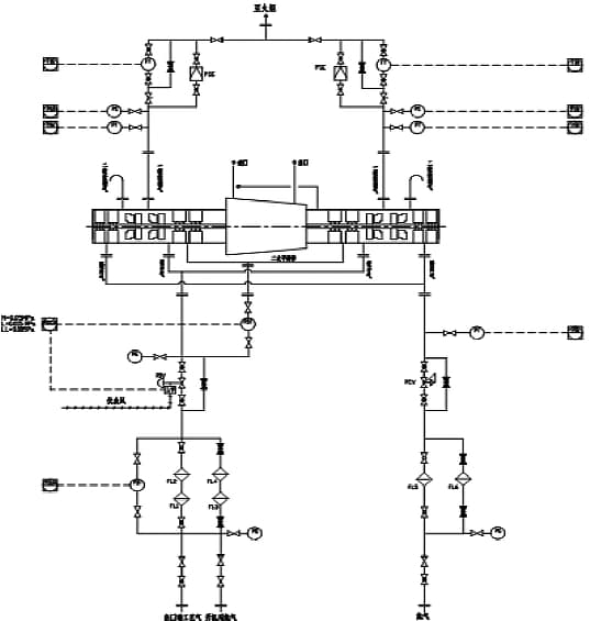
Here, we’ll introduce a typical tandem dry gas seal system.
The schematic diagram below illustrates the system. Under normal conditions, a stream of gas is drawn from the unit’s outlet, passing through two stages of filtration (with a precision of 3μm), resulting in dry, clean gas. This gas serves as the buffer for the dry gas seal, entering the seal chamber.
The pressure is controlled to be slightly above the reference process gas pressure during normal operations (typically 50KPa), preventing impurities like dust and condensate oil in the unrefined process gas from entering the seal face, which could adversely affect the dry gas seal’s performance. The system employs a differential pressure transmitter to measure the pressure difference between the buffer gas and the reference gas.
The signal controls a pneumatic diaphragm regulating valve located at the entrance of the buffer gas, adjusting the inlet pressure to maintain a constant differential pressure with the reference gas. The majority of the buffer gas entering the seal chamber returns to the process gas through a labyrinth seal.
A small portion leaks out through the first-stage dry gas seal, referred to as the first-stage leakage gas. Most of this is safely burned off in a flare.
A stable gas film, essential for long-term ideal operation, can only form under the right pressure differential. The system achieves this by installing a throttle valve at the outlet of the first-stage leakage gas, adjusting the valve aperture to generate the appropriate back pressure. This valve also serves to limit leakage if the first-stage seal fails.
Additionally, nitrogen gas is introduced as an isolating gas through a filter and pressure reduction valve into a subsequent labyrinth seal. Its pressure is slightly higher than the bearing box oil pressure (usually atmospheric pressure), creating a reliable blocking seal system.
This ensures that lubrication oil from the bearing box does not enter the dry gas seal and prevents residual process gas from contaminating the lubrication oil in the bearing area.
A portion of the isolation gas enters the bearing box, while the rest mixes with the small amount of process gas not burned off from the first-stage leakage gas, referred to as the second-stage leakage gas. This can be safely vented to the atmosphere as an environmentally harmless gas.
The primary method of determining if the seal is functioning correctly is by monitoring the first-stage leakage gas. If an anomaly occurs, the pressure and flow rate of the first-stage dry gas seal will significantly increase.
If it reaches a predetermined high alarm value, a pressure transmitter sends a signal to the control room, triggering an alarm signal. This alerts operators to check if the control system pressure is within the designed range.
When the gas leakage amount reaches an extremely high alarm value, it indicates that the dry gas seal has failed, triggering a system shutdown to prevent equipment damage.
VI. Dry Gas Seal Installation Precautions
Dry gas seals are highly precise components that require special attention during installation, disassembly, and use. The following precautions are typically advised:
Non-specialized manufacturers should not disassemble the seals due to their complex assembly relationships, high cleanliness requirements, specialized assembly tools, and the need for precise dynamic balancing.
Transportation, installation, and disassembly all require the use of positioning plates.
The relative position of the cavity and shaft demands high precision; confirm relevant dimensions in advance and adjust with shims if necessary.
During installation, maintain the concentricity of the rotor and the casing, securing the rotor in place.
Typically, start with the installation of the thrust plate end to ensure accurate positioning of the seal at the other end.
Thoroughly clean the seal chamber and all inlet and outlet pipes, ensuring a higher standard of cleanliness than oil pipes.
Do not use grease for lubrication; instead, use silicone grease.
After installing the seal into the unit and removing the positioning plates, ensure that the axial displacement of the rotor does not exceed 2mm.
VII. Maintenance During Dry Gas Seal Operation
Dry gas seals, designed for a broad range of applications, typically require no maintenance under normal conditions.
However, it’s essential to monitor seal leakage daily. An increase in leakage may indicate potential seal failure, and attention should be paid to the following aspects:
Helical groove dry gas seals are designed for unidirectional rotation, so reverse rotation should be avoided. Additionally, running at low speeds below 5 meters per second for extended periods can damage the seal.
Ensure stable flow of sealing gas. Maintaining a steady and uninterrupted sealing gas flow is crucial for the normal operation of dry gas seals.
Avoid operating the seal under negative pressure. Negative pressure in dual-face seals can significantly increase leakage under static conditions and damage the sealing faces under dynamic conditions. For tandem seals, it can lead to contamination by unfiltered process gas, causing rapid seal failure.
Monitor changes in seal leakage. Leakage variations directly reflect the operational status of the dry gas seal. Factors such as fluctuations in process gas, shaft movement, surge, and changes in pressure, temperature, and speed can affect leakage. Normal operation is indicated by stable leakage rates; an upward trend suggests seal malfunction.
When the filter differential pressure reaches the alarm value, switch filters and replace the filter element promptly.
When starting the unit, wait until the dry gas seal control system’s barrier gas has built up sufficient pressure before starting the oil lubrication system.
Upon shutting down the unit, wait for the unit to fully stop and for more than 10 minutes after the oil system has stopped before shutting down the dry gas seal control system.
VIII. Conditions Required for Dry Gas Seal Retrofit Applications
After extensive research and trials, dry gas seals have been widely adopted in industrial applications. Modern industry’s increasing demands for energy efficiency, consumption reduction, and environmental protection have made the reliability, minimal leakage, longevity, and stable operation of shaft seals in centrifugal compressors, which transport large volumes of hazardous gases, a necessity.
Compared to conventional contact mechanical seals, dry gas seals offer unparalleled advantages: longer service life, no process medium leakage, and lower maintenance costs. These benefits align with the goals sought by various types of shaft seals.
Dry gas seals can be successfully retrofitted and applied to centrifugal compressors, centrifugal pumps, reactors, and other equipment, provided the following two conditions are met:
The basic requirement for operating dry gas seals is the availability of a gas source at the site. The gas source can be a process gas or an environmentally friendly inert gas, such as nitrogen, sourced from within the plant or a dedicated nitrogen generator.
The installation site for the shaft seal must have sufficient axial and radial space and appropriate openings.
As the founder of MachineMFG, I have dedicated over a decade of my career to the metalworking industry. My extensive experience has allowed me to become an expert in the fields of sheet metal fabrication, machining, mechanical engineering, and machine tools for metals. I am constantly thinking, reading, and writing about these subjects, constantly striving to stay at the forefront of my field. Let my knowledge and expertise be an asset to your business.
How can we ensure our laser cutting machines operate efficiently while maintaining a clean, safe environment? This article explores effective dust removal methods for laser cutting machines, highlighting both dry…
Why do some gears fail despite advanced gas nitriding techniques? This article delves into the critical steps and common pitfalls in the gas nitriding process for gears, from the importance…
Imagine a device that can "see" the invisible threats around you. Gas sensors do just that—they detect harmful gases in the environment and convert their concentrations into readable signals. This…
Have you ever considered what keeps your car engine from leaking oil or your airplane's turbines running smoothly? Dynamic seals are crucial yet often overlooked components in many machines. This…
In this blog post, we'll explore the world of mechanical seals and introduce you to the top manufacturers who ensure your equipment runs smoothly. Discover the innovations and expertise that…
What if the crucial seal in your pump fails unexpectedly? Pump seals, while often overlooked, are vital to preventing leaks and ensuring smooth operation. This article dives into the different…
Attention all mechanical engineers and manufacturing professionals! Are you struggling with pesky anodizing defects in your aluminum products? Look no further! In this blog post, we'll dive deep into the…
Ever wondered how the world of automation thrives? This article explores top pneumatic companies driving innovation. From Japan to Germany, discover how these industry leaders shape our future. Expect insights…
Have you ever wondered about the fascinating world of casting? This ancient yet ever-evolving manufacturing process shapes our daily lives in countless ways. In this blog post, we'll explore the…