Imagine welding without gas – chaotic and weak. Welding gas is the silent champion, essential for shielding welds from contaminants, stabilizing the arc, and ensuring strong joints. This article explores the types of welding gases, their specific roles, and how they impact the welding process. Readers will gain insights into selecting the right gas for various applications, ensuring optimal welding performance and safety.
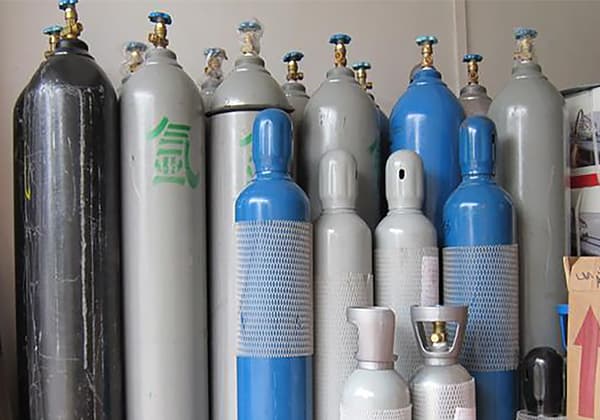
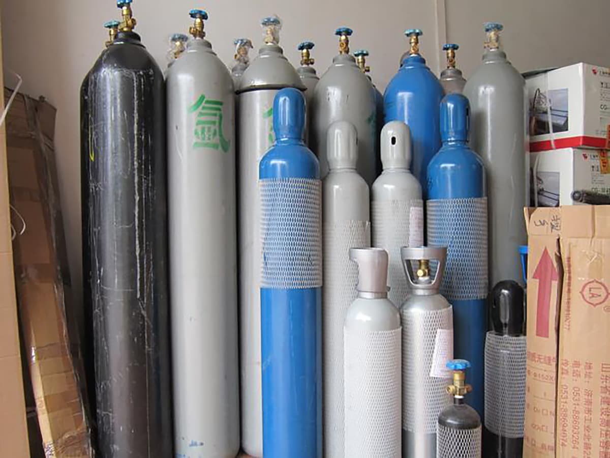
Welding gas mainly refers to the protective gas used in gas shielded welding (carbon dioxide gas shielded welding, inert gas shielded welding), as well as the gas used in gas welding and cutting, including carbon dioxide (CO2), argon gas (Ar), helium gas (He), oxygen gas (O2), combustible gases, mixed gases, etc.
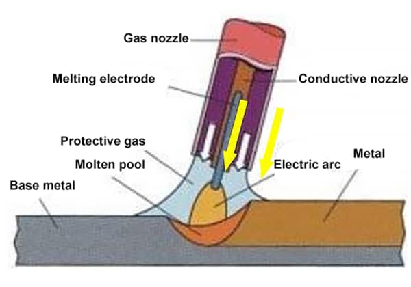
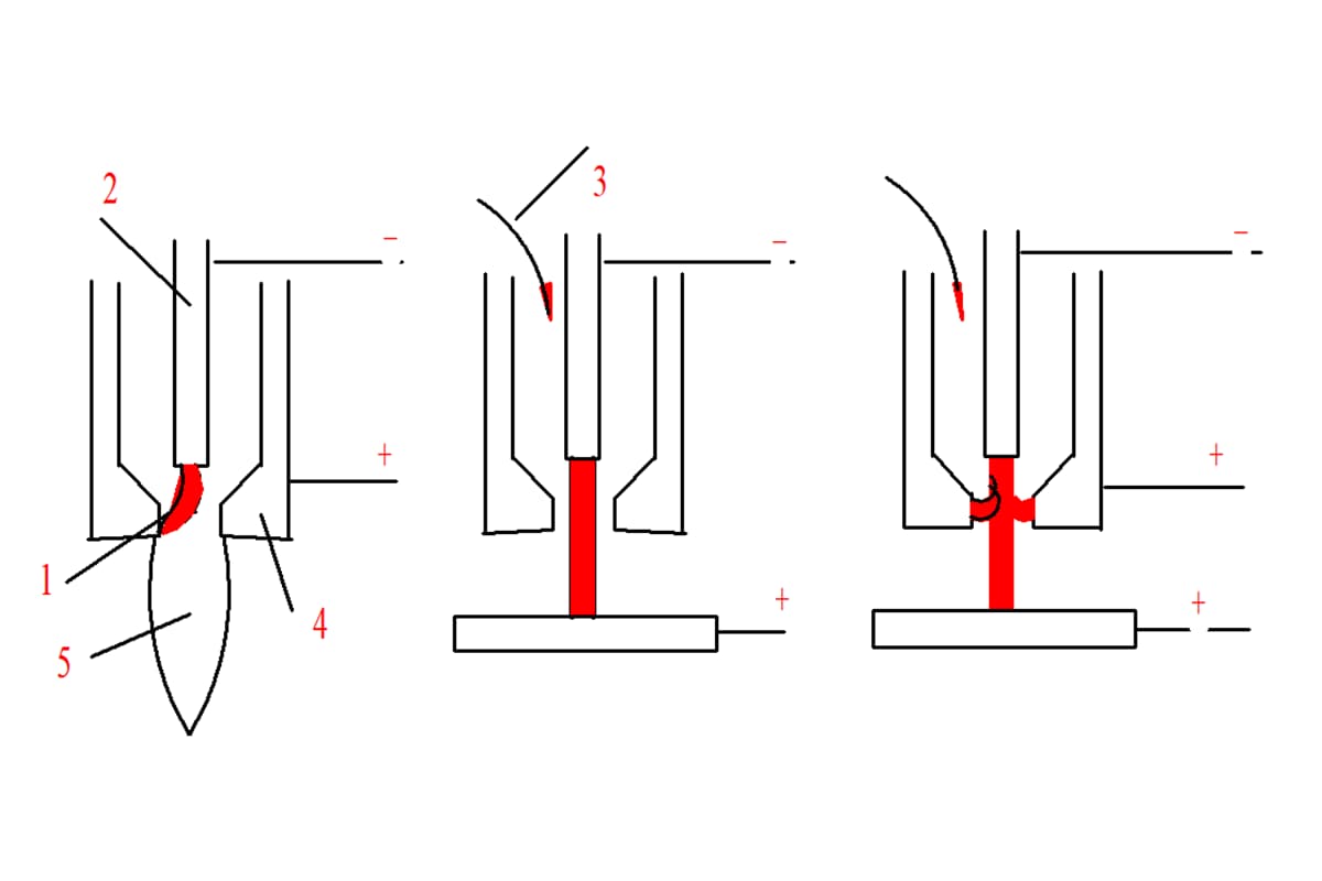
During welding, the protective gas is not only a protective medium for the welding area but also a gas medium for generating an arc.
Gas welding and cutting mainly rely on the high-temperature flame produced by gas combustion to concentrate heat to complete the process.
Therefore, the properties of gas (such as physical and chemical properties, etc.) not only affect the protective effect but also affect the ignition of the arc and the stability of the welding and cutting process.
1. Classification of welding gas
According to the role of various gases in the working process, welding gas is mainly divided into protective gas and gas used in gas welding and cutting.
1.1 Protective gas
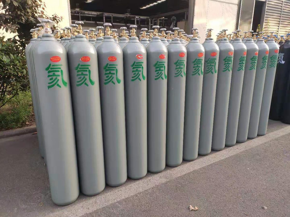
Protective gas mainly includes carbon dioxide (CO2), argon gas (Ar), helium gas (He), oxygen gas (O2), and hydrogen gas (H2).
The International Institute of Welding pointed out that protective gases are classified according to their oxidation potential, and the simple calculation formula for determining the classification index is Classification Index = O2% + 1/2 CO2%.
Based on this formula, protective gases can be classified into five categories according to their oxidation potential. Class I is inert or reducing gas, M1 is weakly oxidizing gas, M2 is moderately oxidizing gas, and M3 and C classes are strongly oxidizing gas. The oxidation potential indexes of each type of protective gas are shown in Table 1.
The classification of protective gases for welding black metals is shown in Table 2.
Table 1: Oxidation potential indexes of various types of protective gases
Type
Ⅰ
M1
M2
M3
C
Oxidation potential index
<1
1~5
5~9
9~16
>16
Table 2: Classification of protective gases for welding black metals
Category
Gas. Quantity
Mixture ratio (expressed in volume percentage) %
Type
Oxygen content in weld metal / %.
Oxidation tendency
Inert
Reductivity
CO2
O2
Ar
He
H2
Ⅰ
112
- - -
- - -
100 - 27~75
- 100 Rem.
- - -
Inert
<0.02
21
- -
- -
85~95 -
--
Rem. 100
Reductivity
M1
22
2~4 -
- 1~3
Rem. Rem.
--
- -
Weakly oxidizing
0.02~0.04
M2
232
15~30 5~15 -
- 1~4 4~8
Rem. Rem. Rem.
- - -
- - -
Moderately oxidizing
0.04~0.07
M3
223
30~40 - 5~20
- 9~12 4~6
Rem. Rem. Rem.
- - -
- - -
Strongly oxidizing
>0.07
C
12
100 Rem.
- <20
- -
- -
- -
1.2 Gas for gas welding and cutting
According to the properties of gases, gases used for gas welding and cutting can be divided into two categories: oxidizing gases (O2) and combustible gases.
When combustible gases are mixed with oxygen and burned, a large amount of heat is released, forming a high-temperature flame with concentrated heat (the highest temperature in the flame can generally reach 2000~3000℃), which can heat and melt metals.
Acetylene is commonly used as a combustible gas for gas welding and cutting. Other combustible gases currently promoted for use include propane, propylene, liquefied petroleum gas (mainly propane), natural gas (mainly methane), etc.
The physical and chemical properties of several commonly used combustible gases are shown in Table 3.
Table 3 Physical and Chemical Properties of Several Commonly Used Combustible Gases.
Gas
(C2H2)
(C3H8)
(C3H6)
(C4H10)
(CH4)
(H2)
Molecular Relativity
26
44
42
58
16
2
Density (in standard state)/kg · m-3
1.17
1.85
1.82
2.46
0.71
0.08
Relative to air mass ratio at 15.6 ℃ (air=1)
0.906
1.52
1.48
2.0
0.55
0.07
Ignition point/℃
335
510
455
502
645
510
Gross calorific value
kJ/m
52963
85746
81182
121482
37681
10048
kg/m
50208
51212
49204
49380
56233
-
Theoretical oxygen demand (oxygen gas volume ratio)
2.5
5
4.5
6.5
2.0
0.5
Actual oxygen consumption (oxygen gas volume ratio)
1.1
3.5
2.6
-
1.5
0.25
Neutral flame temperature ℃
Combustion in oxygen
3100
2520
2870
-
2540
2600
Combustion in air
2630
2116
2104
2132
2066
2210
Flame burning speed/ms
Combustion in oxygen
8
4
-
-
5.5
11.2
Combustion in air
5.8
3.9
-
-
5.5
11.0
Explosion range (volume fraction of combustible gas/%)
In oxygen
2.8~93
2.3~55
2.1~53
-
5.5~62
4.0~96
In the air
2.5~80
2.5~10
2.4~10
1.9~8.4
5.3~14
4.1~74
2. Characteristics of gases for welding
The role of gases in different welding or cutting processes varies, and the selection of gases is also related to the materials being welded.
Therefore, gases with specific physical or chemical properties need to be selected, even a mixture of multiple gases in different situations.
The main properties and uses of commonly used gases in welding and cutting are shown in Table 4, and the characteristics of different gases in the welding process are shown in Table 5.
Table 4 Main Characteristics and Uses of Commonly Used Gases in Welding.
Gas
Symbol
Main properties
Application in Welding
carbon dioxide
CO2
Stable chemical properties, non combustion, non combustion support, can decompose into CO and O at high temperatures, and has a certain degree of oxidation to metals. It can liquefy, absorb a large amount of heat when liquid CO evaporates, and solidify into solid carbon dioxide, commonly known as dry ice
Welding wire can be used as a shielding gas during welding, such as CO2 gas shielded welding and mixed gas shielded welding such as CO2+O2, CO2+Ar, etc
argon
Ar
Inert gas, chemically inert, does not react with other elements at room and high temperatures
Used as a protective gas for mechanical protection during argon arc welding, plasma welding, and cutting
oxygen
O2
A colorless gas that supports combustion and is very active at high temperatures, directly combining with various elements. When oxygen enters the molten pool during welding, it will oxidize metal elements and play a adverse effect
When mixed with combustible gases for combustion, extremely high temperatures can be obtained for welding and cutting, such as oxygen acetylene flames and argon oxygen flames. Mix in proportion with argon, carbon dioxide, etc. for mixed gas shielded welding
acetylene
C2H2
Commonly known as calcium carbide gas, it is less soluble in water, more soluble in alcohol, and more soluble in acetone. It mixes with air and oxygen to form an explosive gas mixture, which burns in oxygen and emits a high temperature of 3500 ℃ and strong light
Able to burn, inactive at room temperature, very active at high temperatures, and can be used as a reducing agent for metal ores and metal oxides. During welding, it can melt deeply into liquid metal and precipitate during cooling, which can easily form pores
Used as a reducing protective gas during welding. Mixed combustion with oxygen can serve as a heat source for gas welding
nitrogen
N2
The chemical properties are not active and can directly combine with hydrogen and oxygen at high temperatures. It is adverse effect to enter the molten pool during welding. It basically does not react with copper and can be used as a protective gas
When nitrogen arc welding, nitrogen is used as a protective gas to weld copper and stainless steel. Nitrogen is also commonly used in plasma arc cutting as an outer protective gas
Table 5 Characteristics of Different Gases in Welding Process.
The heat input of welded parts is higher than that of pure Ar
N2
Purity 99.9%
high
difference
difference
Generation of pores and nitrides in steel
Flat shape
–
2.1 Carbon Dioxide Gas (CO2)
(1) Properties of CO2 gas
CO2 gas is an oxidizing protective gas, and it exists in three states: solid, liquid, and gas. Pure CO2 gas is colorless and odorless. At 0°C and 1 atm (101325 Pa), the density of CO2 is 1.9768 g/L, which is 1.5 times that of air. CO2 is easily soluble in water and has a slightly acidic taste after being dissolved.
When CO2 gas is heated to high temperature, it decomposes into CO and O, releasing -283.24 kJ of energy. Since atomic oxygen is released during the decomposition process, the arc atmosphere has strong gas properties.
In the high-temperature arc zone, three gases (CO2, CO, and O2) often coexist due to the decomposition of CO2 gas. The degree of CO2 gas decomposition is related to the arc temperature during the welding process.
As the temperature increases, the degree of decomposition reaction becomes more intense. When the temperature exceeds 5000K, almost all of the CO2 gas decomposes. The relationship between the degree of CO2 gas decomposition and temperature is shown in Figure 1.
Liquid CO2 is a colorless liquid whose density changes with temperature. When the temperature is below -11℃, its density is greater than that of water, while above -11℃, it is less than that of water. The properties of saturated CO2 gas are shown in Table 6.
The boiling point of CO2 changes from liquid to gas at a very low temperature (-78℃), so industrial CO2 is generally used in its liquid state, which can be vaporized at room temperature. At 0°C and 1 atm, 1 kg of liquid CO2 can be vaporized into 509L of CO2 gas.
Table 6 Properties of Saturated CO2 Gas Pressure
Temperature /℃
Pressure /MPa
Density /kg·L-1
Specific Heat Capacity at Constant Pressure /105J·kg-1·K-1
Temperature /℃
Pressure /MPa
Density /kg·L-1
Specific Heat Capacity at Constant Pressure /105J·kg-1·K-1
Liquid
Gas
Liquid
Gas
Liquid
Gas
Liquid
Gas
-50 -40 -30 -20 -10
0.67 1.0 1.42 1.96 2.58
0.867 0.897 0.931 0.971 1.02
55.4 38.2 27.0 19.5 14.2
3.14 3.33 3.52 3.72 3.94
6.5 6.54 6.55 6.56 6.56
0 +10 +20 +30 +31
3.48 4.40 5.72 7.18 7.32
1.08 1.17 1.30 1.63 2.16
10.4 7.52 5.29 3.00 2.16
4.19 4.46 4.77 5.27 5.59
6.54 6.47 6.3 5.9 5.59
(2) Storage of CO2 gas
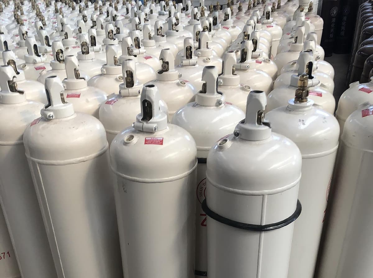
CO2 gas for welding is often in the form of liquid CO2 stored in steel cylinders, which is both economical and convenient. CO2 cylinders are painted black and labeled with yellow letters that read “Liquefied Carbon Dioxide”. The color codes for cylinders containing commonly used welding gases are shown in Table 7.
Table 7 Color Codes for Cylinders Containing Commonly Used Welding Gases
Gas
Symbol
Cylinder Color
Wording
Letter Color
Color Band
Gas
Symbol
Cylinder Color
Wording
Letter Color
Color Band
Hydrogen Oxygen Air Nitrogen Acetylene Carbon Dioxide
H2 O2 — N2 C2H2 CO2
Light green Light blue Black Black White Black
Hydrogen Oxygen Air Nitrogen Acetylene, keep away from fire Liquid Carbon Dioxide
Crimson Black White Light yellow Crimson Yellow
Light yellow White White White — Black
Methane Propane Propylene Argon Helium Liquid Petroleum Gas
CH4 C3H8 C3H6 Ar He —
Brown Brown Brown Silver gray Silver gray Silver gray
Methane Liquefied Propane Liquefied Propylene Argon Helium Liquefied Petroleum Gas
White White Light yellow Dark green Dark green Crimson
Light yellow — — WhiteWhite —
① If the working pressure is 19.6 MPa, one color band shall be added; if the working pressure is 29.4 MPa, two color bands shall be added.
The standard steel cylinder for CO2 gas usually has a capacity of 40 kg and can be filled with 25 kg of liquid CO2.
The 25 kg of liquid CO2 accounts for about 80% of the volume of the cylinder, and the remaining 20% space is filled with gaseous CO2.
The pressure value indicated on the cylinder pressure gauge is the saturation pressure of this part of the gas. This pressure depends on the ambient temperature. As the temperature increases, the saturation pressure increases, and as the temperature decreases, the saturation pressure decreases.
Only when all the liquid CO2 in the steel cylinder has evaporated into gas, will the pressure of the gas in the cylinder gradually decrease with the consumption of CO2 gas.
The liquid CO2 contained in a standard steel cylinder can vaporize into 12,725 L of CO2 gas. According to the selection of CO2 gas flow rate during welding (see Table 8), if the average consumption of CO2 gas during welding is 10 L/min, one liquid CO2 cylinder can be used continuously for about 24 hours.
Table 8: Selection of CO2 gas flow rate during welding
Welding method
CO2 gas flow /L · min-1
Fine wire CO2 welding
5~15
Coarse wire CO2 welding
15~25
Coarse wire high current CO2 welding
25~50
The pressure of a standard CO2 steel cylinder when it is full is 5.0-7.0 MPa. As the pressure inside the cylinder decreases during use, the amount of water vaporized from the moisture dissolved in the liquid CO2 also increases.
The relationship between the water content in CO2 gas and the pressure inside the cylinder is shown in Figure 6.2.
Empirical data shows that when the gas pressure inside the cylinder is lower than 0.98 MPa (at 20℃), the CO2 in the steel cylinder should not be used anymore because the liquid CO2 has basically evaporated.
If it continues to be used, welding defects such as pores will occur in the weld metal, and CO2 gas must be refilled.
(3) The purity of CO2 gas for welding
The mass fraction of water that can be dissolved in liquid CO2 is 0.05%, and excess water settles at the bottom of the cylinder in a free state.
These water molecules evaporate with CO2 during the welding process and mix into the CO2 gas, directly entering the welding area.
Therefore, moisture is the main harmful impurity in CO2 gas. The hydrogen content of the weld metal varies depending on the humidity of the CO2 gas, as shown in Table 9.
The relationship between CO2 dew point and the hydrogen content of the weld metal is shown in Figure 3.
Table 9: Hydrogen content of the weld metal under different humidity levels of CO2 gas.
Humidity of CO2
/g · m3
0.85
1.35
Hydrogen content per 1kg of weld metal
/mg
29
45
Humidity of CO2
/g · m3
1.92
15
Hydrogen content per 1kg of weld metal
/mg
47
55
As the water content in CO2 gas increases (i.e., as the dew point temperature rises), the hydrogen content in the weld metal gradually increases, the plasticity decreases, and even defects such as pores may occur.
Therefore, CO2 gas used for welding must have high purity. The technical requirements for liquid CO2 used for welding are shown in Table 10.
In China, the general requirement is that CO2 > 99%, O2 < 0.1%, H2O < 0.05%; while in some foreign countries, CO2 > 99.8%, H2O < 0.0066%, dew point below -40℃ (equivalent to GB’s Class I) is also required.
Table 10: Technical requirements for liquid CO2 used for welding (GB 6052-85).
Indicator Name
Class I %
Class II %
class a
second level
Level 3
CO2 content moisture content
≥99.8 ≤0.005
≥99.5 ≤0.05
≥99.0 ≤0.10
≥99.0 –
If the commercially available CO2 gas used on the production site has a high water content and low purity, it should be purified. The commonly used purification methods are as follows:
a. Invert the new CO2 gas steel cylinder and let it stand for 1-2 hours so that the water can settle at the bottom. Then open the valve of the inverted cylinder and drain the water 2-3 times, with an interval of about 30 minutes between each drain. After draining, return the steel cylinder to its upright position.
b. Before using the steel cylinder after water drainage treatment, release the gas continuously for 2-3 minutes because the gas in the upper part usually contains more air and water, which were mixed into the cylinder during filling.
c. Connect a high-pressure dryer and a low-pressure dryer in series in the CO2 supply pipeline. The desiccant can be silica gel, anhydrous calcium oxide or dehydrated copper sulfate to further reduce the water content in the CO2 gas. The used desiccant can be dried and reused.
d. Do not use the CO2 when the gas pressure inside the cylinder drops to 0.98 MPa.
When CO2 is used as a shielding gas for welding in poorly ventilated or narrow spaces, ventilation measures must be strengthened to prevent the concentration of CO2 from exceeding the permitted concentration (30 kg/m2) specified by national regulations, which would affect the health of welders.
2.2 Argon (Ar)
(1) Properties of Argon
Argon is the most abundant rare gas in the air after nitrogen and oxygen, with a volume fraction of about 0.935%.
Argon is colorless and odorless. At 0℃ and 1 atm (101325 Pa), its density is 1.78 g/L, about 1.25 times that of air. The boiling point of argon is -186℃, between the boiling points of oxygen (-183℃) and nitrogen (-196℃). Argon can be obtained simultaneously while producing oxygen by fractional distillation of liquid air.
Argon is an inert gas that does not react chemically with metals during welding and does not dissolve in liquid metal.
Therefore, it can avoid the burning loss of metal elements in the weld and other welding defects, making the welding metallurgical reaction simple and easy to control, providing favorable conditions for obtaining high-quality welds.
The relationship between thermal conductivity and temperature of Ar, He, H2, and N2 is shown in Figure 4. It can be seen that argon has the lowest thermal conductivity and belongs to a monoatomic gas, which will not absorb heat due to decomposition at high temperatures.
Therefore, the heat loss of arc generated in argon gas is relatively small. Argon has a high density and is not easily lost during protection, resulting in good protective effect. The wire metal can easily transition into a stable axial jet flow, with minimal spatter.
(2) Storage of Argon
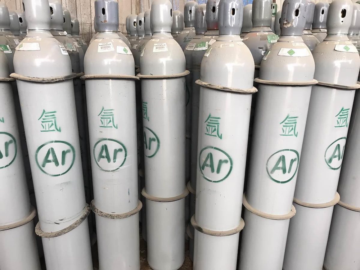
Argon can be stored and transported in liquid form below -184℃, but steel cylinders filled with argon gas are commonly used for welding. The argon gas cylinder is painted silver-gray and marked with green (Ar).
Currently, the commonly used argon gas cylinder volumes in China are 33L, 40L, and 44L. When the cylinder is full and placed under 20℃, the pressure inside the cylinder should be 15 MPa.
It is strictly prohibited to knock or collide with the argon gas cylinder during use; do not use fire to thaw the valve when it freezes; do not use electromagnetic weight-lifting machines to transport argon gas cylinders; prevent exposure to sunlight in summer; the gas inside the cylinder should not be completely exhausted; and argon gas cylinders should generally be kept upright.
Note: The content of gases is expressed in volume fraction; the content of moisture is expressed in mass fraction.
Table 12 Argon Purity Used for Welding Different Materials
Base Metal
Gas Content / %
Ar
N2
O2
H2O
Titanium, Zirconium, Molybdenum, Niobium and their alloys
Aluminum, Magnesium and their alloys, Chromium-Nickel Heat-Resistant Alloys
Copper and Copper alloys, Chromium-Nickel Stainless Steel
≥99.98 ≥99.9 ≥99.7
≤0.01 ≤0.04 ≤0.08
≤0.005 ≤0.05 ≤0.015
≤0.07 ≤0.07 ≤0.07
If the impurity content of argon gas exceeds the specified standard during welding, it not only affects the protection of molten metal but also easily causes defects such as porosity and slag inclusion in the weld, which affects the quality of the weld joint and increases the tungsten electrode’s burn loss.
2.3 Helium (He)
(1) Properties of Helium Gas
Helium gas is also a colorless and odorless inert gas that does not form compounds with other elements like argon gas. It is a monoatomic gas and is difficult to dissolve in other metals. Its boiling point is -269℃.
Helium gas has a high ionization potential, making it difficult to arc weld. Compared with argon gas, helium gas has a higher thermal conductivity, resulting in a higher voltage and arc temperature at the same welding current and arc intensity.
As a result, the heat input of the base metal is higher, the welding speed is faster, the arc column is thinner and more concentrated, and the weld penetration is greater. This is the main advantage of using helium gas for arc welding, but its arc stability is slightly inferior to that of argon arc welding.
Due to its light atomic weight and small density, a much larger flow rate of helium gas is required to effectively protect the welding area.
Because of its expensive price, it is only used in certain special applications such as welding of key components such as cooling rods for nuclear reactors and thick aluminum alloys. The characteristics of argon gas and helium gas during welding are compared in Table 13.
Table 13 Comparison of Characteristics of Argon and Helium Gases During Welding
Gas
Symbol
characteristic
argon
Ar
(1) Low arc voltage: produces less heat and is suitable for tungsten argon arc welding of thin metals.
(2) Good cleaning effect: suitable for welding metals that form hard-to-melt oxide skins, such as aluminum, aluminum alloys, and iron-based alloys with high aluminum content.
(3) Easy to ignite the arc: particularly important when welding thin metal pieces.
(4) Lower gas flow rate: Argon gas has a higher density than air, which means it provides better protection and is less affected by air flow than helium gas.
(5) Suitable for flat and horizontal welding: Argon gas can better control the molten pool during flat and horizontal welding, but its protective effect is inferior to helium gas.
(1) High arc voltage: produces more heat and is suitable for welding thick metals and metals with high thermal conductivity.
(2) Small heat-affected zone: results in less deformation during welding and higher mechanical properties.
(3) Higher gas flow rate: Helium gas has a smaller density than air, and its gas flow rate is 0.2 to 2 times larger than that of argon gas. Helium gas is more sensitive to airflow than argon gas but provides better protection for flat and horizontal welding.
(4) High automatic welding speed: when the welding speed is greater than 66mm/s, smaller welds with fewer porosities and undercutting can be obtained.
Because the arc of helium gas is unstable, and the cathode cleaning effect is not obvious, tungsten helium arc welding generally uses DC positive connection. Even for welding aluminum, magnesium, and their alloys, an AC power source is not used. Helium arc has a large and concentrated heat generation, strong arc penetration, and when the arc is short, DC positive connection also has some effect on removing the oxide film.
In DC positive connection helium arc welding of aluminum alloy, the single-pass welding thickness can reach 12mm, and the front and back welding can reach 20mm. Compared with AC argon arc welding, it has a greater depth of fusion, narrower weld bead, smaller deformation, smaller softening zone, and less metal over-burning. For heat-treated strengthening aluminum alloys, the room temperature and low-temperature mechanical properties of the joints are better than those of AC argon arc welding.
(2) Purity of Helium Gas Used for Welding
As a protective gas used for welding, the purity of helium gas is generally required to be 99.9% to 99.999%. Furthermore, it also depends on the type, composition, and performance of the base metal being welded and the quality requirements of the welding joint.
In general, to prevent metals from oxidizing or nitriding during welding of active metals and to improve the quality of the welding joint, high-purity helium gas should be selected. Technical requirements for using helium gas for welding are shown in Table 14.
Table 14 Technical Requirements of Using Helium Gas for Welding
Indicator Name
High purity ammonia
Pure ammonia
Industrial ammonia
First level product
Secondary product
First level product
Secondary product
Ammonia content (≥)/%10-6
99.999
99.99
99.99
99.9
98
Neon containing (≤)/10-6
4.0
15
25
(Ne+H)≤800
(Ne+H2 +O2+Ar)≤2.0%
Hydrogen content (≤)/10-6
1.0
3.0
5.0
Total oxygen content (≤)/10-6
1.0
3.0
5.0
29
Nitrogen content (≤)/10-6
2.0
10
20
50
CO content (≤)/10-6
0.5
1.0
1.0
Not specified
Not specified
CO2 content (≤)/10-6
0.5
1.0
1.0
Methane content (≤)/10-6
0.5
1.0
1.0
Moisture content (≤)/10-6
3.0
10
15
30
Note: The gas content in the table is expressed in volume fraction, and the water content is expressed in mass fraction.
2.4 Properties of Oxygen Gas
(1) Properties of Oxygen Gas:
Oxygen gas is a colorless, odorless, tasteless, and non-toxic gas at room temperature and pressure. At 0℃ and 1 atm (101325Pa), the density of oxygen gas is 1.43kg/m3, which is greater than that of air. The liquefaction temperature of oxygen is -182.96℃, and liquid oxygen is light blue. At room temperature, oxygen exists in large quantities in the form of compounds and free states in air and water.
Oxygen gas itself cannot burn, but it is a highly active combustion-supporting gas that can react with many elements to produce oxides. In general, intense oxidation reactions are referred to as combustion. Gas welding and cutting use combustible gases and the heat released from oxygen combustion as heat sources.
(2) Production of Oxygen Gas:
There are many methods for producing oxygen gas, such as chemical methods, electrolysis of water, and liquefaction of air.
However, in industrial production, the liquefaction of air method is widely used. Air is compressed and cooled to below -196℃ to turn it into a liquid. Then, as the temperature rises, nitrogen in the liquid air evaporates into a gas when the temperature rises to -196℃.
As the temperature continues to rise to -183℃, oxygen begins to vaporize. The gaseous oxygen is then compressed to 120-150 atm by a compressor and stored in special oxygen cylinders for use and storage.
(3) Storage of Oxygen Gas:
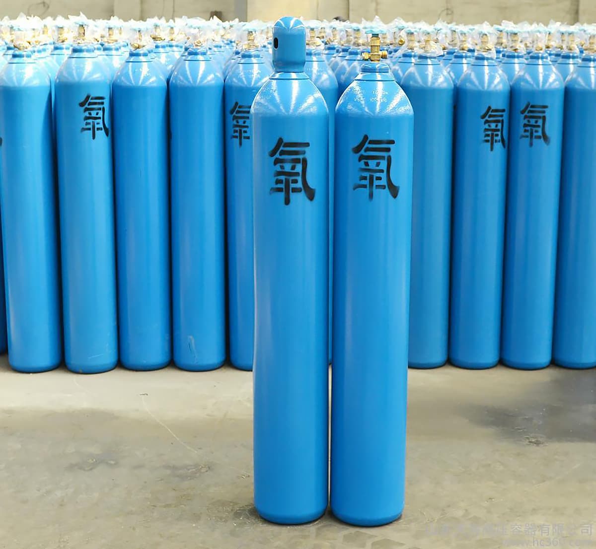
Oxygen gas is generally stored and transported in special oxygen cylinders, and the outside of the oxygen cylinders should be painted sky blue and marked with the words “oxygen” in black paint.
Oxygen cylinders should be inspected every 3-5 years at the inflation factory during use, checking the volume and quality of the cylinder, as well as inspecting for corrosion and cracking. The dimensions and filling capacity of commonly used oxygen cylinders are shown in Table 15.
The supply of oxygen gas during operation is mainly regulated by the pressure reducer on the cylinder. The main technical parameters of the pressure reducer for oxygen cylinders are shown in Table 16, and the common faults and prevention measures of the pressure reducer are shown in Table 17.
Table 15 Dimensions and Filling Capacity of Commonly Used Oxygen Cylinders
External dimensions /mm
Internal volume /L
Bottle weight /kg
Bottle valve model
Gas capacity/m3 (at 20 ℃, 14.7MPa)
external diameter
height
219
1150±20
33
47
QF-2 Copper Valve
5
1250±20
36
53
5.5
1370±20
40
57
6
1480±20
44
60
6.5
1570±20
47
63
7
Table 16 Main Technical Parameters of Pressure Regulator for Gas Cylinder
Pressure reducer model
QD1
QD-2A
QD-2A
DJ-6
SJ7-10
QD-20
QW2-16/0.6
name
Single-stage oxygen pressure regulator
Two-stage oxygen pressure regulator
Single-stage acetylene pressure regulator
Single-stage propane pressure regulator
Pressure gauge specification /MPa
High voltage meter
0~24.5
0~24.5
0~24.5
0~24.5
0~24.5
0~24.5
0~24.5
Low voltage meter
0~3.92
0~1.568
0~0.392
0~3.92
0~3.92
0~0.245
0~0.157
Maximum working pressure /MPa
Intake side
14.7
14.7
14.7
14.7
14.7
1.96
1.96
Working side
2.45
0.98
0.196
1.96
1.96
0.147
0.059
Working pressure adjustment range / MPa
0.1~2.45
0.1~0.98
0.01~0.2
0.1~2.0
0.1~1.96
0.01~0.05
0.02~0.05
Maximum gas supply capacity / m3·h-1
80
40
12
180
-
9
-
Outlet orifice diameter / mm
6
5
3
-
5
4
-
Safety valve relief pressure / MPa
2.8~3.8
1.1~1.6
-
2.16
2.16
0.2~0.3
0.07~0.1
Weight / kg
4
2
2
2
3
2
2
Overall dimensions / mm
200×200×210
165×170×160
165×170×160
170×200×142
200×170×220
170×185×315
165×190×160
Table 17 Common Faults of Pressure Regulators and Preventive Measures.
Common Faults
Fault Location and Cause
Preventive Measures and Repair
Leakage of Pressure Regulator
Leakage at the Joint of Pressure Regulator, Loosening of Threaded Connection or Damage to Gasket.
Tighten the screw; replace the gasket or add asbestos rope.
Leakage of Safety Valve; Damage to Gasket or Deformation of Spring.
Adjust the spring; replace the new valve gasket (blue steel paper and asbestos rope).
Damage to or Inability to Tighten the Membrane on the Pressure Regulator Cover, Resulting in Leakage.
Replace the rubber diaphragm or tighten the screw.
Pressure Gauge Crawls Up (Self-Flow) and Gas Flows Out after Loosening the Adjustment Screw (Low Pressure Gauge Continues to Climb).
There are contaminants on the valve or valve seat, and the sealing gasket or valve seat is not level; the turning spring is damaged, and the clamping force is insufficient.
Clean the contaminants on the valve, use fine gauze to level the uneven valve seat. If there are cracks, replace with new ones and adjust the spring length.
When the Oxygen Cylinder Valve is Opened, the High Pressure Gauge Indicates the Presence of Oxygen, but the Low Pressure Gauge Does Not Respond or is Not Sensitive Enough.
The adjusting screw has been tightened all the way, but the working pressure does not rise or rises very little. The reason for this is that the main spring is damaged or the transmission rod is bent.
Remove the pressure regulator cover and replace the main spring and transmission rod.
During operation, the oxygen pressure drops or the gauge needle jumps violently. The reason for this is internal freezing of the pressure regulator.
After thawing with hot water, blow dry the moisture.
The low-pressure gauge has indicated the working pressure, but it suddenly drops during use. The reason for this is that the oxygen cylinder valve is not fully open.
Open the oxygen valve further.
Compared with gaseous oxygen, liquid oxygen has the advantages of low energy consumption, high purity of supplied oxygen (up to 99.9% or more), and high transport efficiency. Therefore, industrial oxygen is sometimes supplied in liquid form. The ways to supply liquid oxygen to users or on-site are as follows:
a. Set up a gaseous oxygen storage tank in the user department, and fill the tank with gaseous oxygen from the liquid transport tank equipped with vaporization and compression equipment.
b. Set up a liquid storage tank and vaporization equipment in the user department, and fill the tank with liquid oxygen from the liquid oxygen transport tank.
c. Install small liquid oxygen containers and corresponding vaporizers on carts, configure them on site, and move them at any time according to usage needs. This method is only suitable for factories and sites with small oxygen consumption.
There are two types of liquid oxygen storage tanks: mobile and fixed. The specifications and main technical parameters of mobile liquid oxygen containers are shown in Table 18, and those of fixed liquid oxygen containers are shown in Table 19.
Table 18: Specifications and Main Technical Parameters of Mobile Liquid Oxygen Containers.
Model number
CD4-50
CD4-100
CD4-175
Model number
CD4-50
CD4-100
CD4-175
Technical parameters
Container capacity in liters
50
100
175
Technical parameters
Height/mm
1160
1150
1535
Operating pressure in MPa
1.372
1.372
1.372
Outer diameter/mm
322
505
505
Daily evaporation rate in percentage
2.5
2.3
1.2~1.6
Cart weight/㎏
45
81
117
Empty container weight in kilograms
60
90
115
Table 19: Specifications and main technical parameters of fixed liquid oxygen containers.
Model number
CF-2000
CF-3500
CF-5000
CF-10000
Technical parameters
Geometry volume /m3
2.10
3.68
5.25
10.5
Effective volume /m3
2
3.5
5
10
Inner diameter of inner cylinder /mm
1200
1400
1400
2000
Inner diameter of outer cylinder /mm
1700
2000
2000
2600
Daily evaporation rate /%
0.9
0.55
0.45
0.4
Gas supply capacity /m3·h-1
Optional according to user requirements
(Outer diameter x length) /mm
1712×3245
2016×3800
2024×5000
2620×4318
Nominal pressure /MPa
0.196
0.784
1.568
0.196
0.784
1.568
0.196
0.784
1.568
0.196
0.784
1.568
Empty container weight /kg
1.9
2.0
2.3
4.4
4.6
5.0
5.3
5.6
6.0
7.8
7.8
9.0
As oxygen is a combustion-supporting gas with extremely active properties, when the gas cylinder is full, the pressure can reach up to 150 atmospheres. There is a risk of explosion if not handled carefully during use and transportation of oxygen.
Therefore, special attention should be paid to the following points:
a) Oil proof. It is forbidden to touch the oxygen cylinder and its ancillary equipment with gloves stained with oil; during transportation, it must never be placed together with flammable substances and oils.
b) Shockproof. Oxygen cylinders must be securely placed to prevent vibration that can cause oxygen explosions. When standing upright, iron hoops or chains should be used for fixation; when lying down, wooden pads should be used to prevent rolling, and two rubber shock absorbers should be installed on the cylinder body. During transportation, a dedicated vehicle should be used for transport.
c) Heat resistant. Oxygen cylinders, whether in storage or transportation, should be kept at least 10m away from the heat source. In summer, while working outdoors in sunlight, it must be covered with canvas to prevent explosions.
d) Anti-freeze. When using an oxygen cylinder in winter, if the oxygen cylinder valve freezes, cover it with a cloth soaked in hot water to thaw it. Under no circumstances should fire be used to heat and defrost it, to avoid causing explosion accidents.
e) Before opening the oxygen cylinder valve, check whether the pressure nut is tightened. When rotating the handwheel, it must be smooth, without excessive force, and people should stand on the side of the oxygen outlet. When using oxygen, do not use up all the oxygen in the cylinder, leaving at least 1-3 atmospheres of oxygen.
f) When the oxygen cylinder is not in use, the protective cover must be placed on the valve to prevent damage.
g) During the repair of the oxygen cylinder valve, special attention should be paid to safety to prevent the oxygen cylinder from exploding.
(4) Purity of welding oxygen
As industrial oxygen is usually produced by liquefaction and air separation, it often contains nitrogen. The presence of nitrogen during welding and cutting not only lowers the flame temperature, affecting production efficiency, but also reacts with the melted iron to form nitride iron, reducing the strength of the weld.
Therefore, the purity of oxygen has a great impact on the efficiency and quality of gas welding and cutting. The higher the purity of oxygen used for gas welding and cutting, especially when cutting, the better.
Oxygen is also commonly used as an additional gas for inert gas shielded welding to refine droplets, overcome arc cathode spot drifting, increase heat input of base metal, and improve welding speed.
Table 20: Technical requirements for welding oxygen in gaseous state. High-purity Class I or II first-grade oxygen should be used for high-quality gas welding and cutting to obtain the required thermal conductivity.
Indicator name
Class I
Class Ⅱ
Oxygen content (volume fraction ≥) / %.
99.5
99.5
99.2
Moisture
Free water (≤) / mL.
-
100
100
Dew point (≤) / ℃
-43
-
-
2.5 Flammable Gases
There are many types of flammable gases used for welding, but currently the most widely used ones in gas welding and cutting are acetylene gas (C2H2), followed by propane gas.
Hydrogen gas, natural gas or coal gas can also be used as flammable gases depending on local conditions or the material being welded or cut. When choosing a flammable gas, the following factors should be considered:
a) The heat generated should be high, which means that the amount of heat released by the complete combustion of flammable gas per unit volume should be high.
b) The flame temperature should be high, generally referring to the highest temperature of the flame burning in oxygen.
c) The amount of oxygen required for combustion of flammable gas should be small, to improve its economy.
d) The explosive limit range should be small.
e) Transportation should be relatively convenient.
(1) Acetylene (C2H2)
1) Properties of acetylene
Acetylene is an unsaturated hydrocarbon (C2H2), which is a colorless gas at room temperature and 1 atmosphere pressure (101325Pa). Generally, when welding with acetylene, there is a special odor due to impurities such as H2S and PH3.
The flame temperature of acetylene burning in pure oxygen can reach about 3150℃, and the heat is relatively concentrated. It is currently the most widely used flammable gas in gas welding and cutting.
The density of acetylene is 1.17kg/m3. The boiling point of acetylene is -82.4℃, and it becomes liquid at -83.6℃. At temperatures below -85℃, it becomes solid. Gaseous acetylene can be dissolved in water, acetone and other liquids. At 15℃ and 1 atmosphere pressure, 1L of acetone can dissolve 23L of acetylene. When the pressure is increased to 1.42MPa, 1L of acetone can dissolve about 400L of acetylene.
Acetylene is an explosive gas, and its explosion characteristics are as follows:
a) When the pressure of pure acetylene reaches 0.15MPa and the temperature reaches 580-600℃, it will explode when exposed to fire. The pressure of acetylene in the generator and pipeline should not exceed 0.13MPa.
b) When acetylene is mixed with air or oxygen, the explosiveness will be greatly increased. When acetylene is mixed with air, calculated by volume, when acetylene accounts for 2.2%-81%; when acetylene is mixed with oxygen, calculated by volume, when acetylene accounts for 2.8%-93%, the mixed gas will ignite spontaneously (the spontaneous ignition temperature of acetylene-air mixture is 305℃, and the spontaneous ignition temperature of acetylene-oxygen mixture is 300℃), or it will explode when exposed to sparks, even at normal pressure.
Acetylene mixed with chlorine gas, hypochlorite and other substances will explode when exposed to sunlight or heat. Acetylene mixed with nitrogen, carbon monoxide and water vapor will reduce the risk of explosion.
c) Acetylene can also form explosive substances such as acetylene copper and acetylene silver when in contact with copper, silver, etc. for a long time.
d) Dissolving acetylene in liquid can greatly reduce its explosiveness.
e. The explosiveness of acetylene is related to the shape and size of the container used for storage. Containers with smaller diameters are less likely to explode. Acetylene can be stored in containers with capillary-shaped materials, and even if the pressure increases to 2.65 MPa, explosions will not occur.
2) Industrial acetylene is mainly produced by decomposing carbide through acetylene generators.
There are many types of acetylene generators commonly used for the production of acetylene, which can be classified according to the pressure produced: medium-pressure acetylene generators (which produce acetylene gas at a gauge pressure of 0.0069-0.127 MPa) and low-pressure acetylene generators (which produce acetylene gas at a gauge pressure lower than 0.0069 MPa).
They can also be classified according to different ways of contact between carbide and water, such as drainage, carbide-in-water, and combined drainage methods. According to their positional forms, they can be further classified into mobile or fixed types. Types and technical specifications of medium-pressure acetylene generators are shown in Table 21.
For high-quality gas welding, purified and dried acetylene should be used. Industrial carbide is made by melting quicklime and coke in an electric furnace. The quality level and performance of carbide used for acetylene gas welding and cutting should meet the requirements specified in Table 22.
Table 21. Types and technical specifications of medium-pressure acetylene generators.
Model
Q3-0.5
Q3-1
Q3-3
Q4-5
Q4-10
Normal production rate /m3 · h-1
0.5
1
3
5
10
Acetylene working pressure /MPa
0.045~0.1
0.045~0.1
0.045~0.1
0.1~0.12
0.045~0.1
Safety valve leakage pressure /MPa
0.115
0.115
0.115
0.15
0.15
Bursting pressure of explosion-proof film /MPa
0.18~0.28
0.18~0.28
0.18~0.28
0.18~0.28
0.18~0.28
Maximum temperature of acetylene in the gas chamber /℃
90
90
90
90
90
Calcium carbide can be loaded into one container /kg
2.4
5.0
13.0
12.5
25.5
Permissible particle size of calcium carbide /mm
25×5050×80
25×5050×80
25×5050×80
15~25
15×2525×5050×80
Generator water capacity /L
30
65
330
338
818
structural style
Drainage type
Drainage type
Drainage type
joint
joint
Installation form
Mobile
Mobile
Fixed
Fixed
Fixed
External dimensions /mm
Length
515
1210
1050
1450
1700
Width
505
675
770
1370
1800
Height
930
1150
1755
2180
2690
Net weight (excluding water and carbide) / kg
45
115
260
750
980
Table 22: Quality grades and performance of carbide for acetylene gas welding and cutting.
Indicator Name
index
First level product
Secondary product
Grade III product
Grade 4 product
Calcium carbide particle size /mm
80~200
Faqi Li /Lkg-1
305
285
265
235
50~80
305
285
255
235
50~80
300
280
250
230
PH content in acetylene (volume fraction) /%
0.08
0.08
0.08
0.08
HS content in acetylene (volume fraction) /%
0.15
0.15
0.15
0.15
3) Storage of acetylene gas
Due to the risk of explosion when pressurized, direct pressurized bottling cannot be used for storing acetylene. In industry, its high solubility in acetone is utilized, and acetylene is filled into containers that contain acetone or a porous substance, commonly known as dissolved acetylene or bottled acetylene.
The acetylene cylinder is usually painted white with the words “acetylene” in red paint. The cylinder is filled with porous material soaked in acetone, which allows acetylene to be safely stored at a pressure of 1.5 MPa inside the cylinder.
When in use, an acetylene regulator must be used to reduce the pressure to below 0.103 MPa before use. The porous material is typically a mixture of lightweight and porous activated carbon, sawdust, pumice, and diatomaceous earth.
For welding, acetylene purity of over 98% is generally required. The filling conditions are regulated: a filling pressure no greater than 1.55 MPa at 15°C. Bottled acetylene is currently a widely promoted and applied method due to its safety, convenience, and economy.
(2) Petroleum gas
Petroleum gas is a product or byproduct of petroleum processing. The gases used in cutting include elemental gases such as propane and ethylene, as well as byproducts such as mixed multicomponent gases from refining, usually composed of propane, butane, pentane, and butene.
1) Propane (C3H8)
Propane is a commonly used fuel gas in cutting, with a relative molecular mass of 44.094. Its total calorific value is higher than acetylene’s, but the combustion heat of a unit mass molecule is lower than that of acetylene’s. As a result, the flame temperature is lower, and the flame heat is more dispersed. The chemical reaction formula for complete combustion of propane in pure oxygen is: C3H8 + 5O2 → 3CO2 + 4H2O (1)
From the above equation, it can be seen that the theoretical oxygen consumption of 1 volume of propane completely burned is 5 volumes. When propane is burned in air, the actual oxygen consumption is 3.5 volumes, forming a neutral flame with a temperature of 2520°C. The highest temperature of the oxidizing flame is about 2700°C. The combustion speed of the oxygen-propane neutral flame is 3.9 m/s, and the danger of tempering is small, and its explosion range is narrow, between 23% and 95% in oxygen. However, its oxygen consumption is higher than acetylene’s, it has a high ignition point and is not easy to ignite.
2)Propylene (C3H6)
Propylene has a relative molecular mass of 42.078, with a lower total calorific value than propane but higher flame temperature. The chemical reaction formula for complete combustion of propylene in pure oxygen is:
C3H6 + 4.5O2 → 3CO2 + 3H2O (2)
The theoretical oxygen consumption of 1 volume of propylene completely burned is 4.5 volumes. When burned in air, the actual oxygen consumption is 2.6 volumes, forming a neutral flame with a temperature of 2870°C. When the propylene to oxygen ratio is 1:3.6, an oxidizing flame can be formed, which has a higher flame temperature.
Due to its lower oxygen consumption than propane and higher flame temperature, propylene was used as a cutting gas in some countries.
3)Butane (C4H10)
Butane has a relative molecular mass of 58.12, with a higher total calorific value than propane. The chemical reaction formula for complete combustion of butane in pure oxygen is:
C4H10 + 6.5O2 → 4CO2 + 5H2O
The theoretical oxygen consumption of 1 volume of butane completely burned is 6.5 volumes. When burned in air, the actual oxygen consumption is 4.5 volumes, higher than that of propane. Butane mixed with oxygen or air has a narrow explosive range (volume fraction of 1.5% to 8.5%) and is not prone to backfire. However, due to its low flame temperature, it cannot be used alone as a cutting fuel.
4)Liquefied Petroleum Gas
Liquefied petroleum gas is a byproduct of petroleum processing, mainly composed of hydrocarbons such as propane (C3H8), butane (C4H10), propylene (C3H6), butene (C4H8), and small amounts of acetylene (C2H2), ethylene (C2H2), pentane (C5H12), etc. These hydrocarbons exist in the gas phase at ordinary temperatures and atmospheric pressure, but they can be liquefied with a pressure of about 0.8-1.5 MPa for storage and transportation.
In industry, gaseous petroleum gas is generally used. Petroleum gas is a slightly odorous colorless gas, with a density larger than that of air at standard conditions, about 1.8-2.5 kg/m3. The main components of liquefied petroleum gas can form explosive mixtures with air or oxygen, but the explosive range is relatively small compared to acetylene. Liquefied petroleum gas is cheaper and safer than acetylene, with a smaller risk of backfire.
However, it requires more oxygen for safe combustion, has a lower flame temperature, and burns slower. Therefore, modifications are needed for cutting torches using liquefied petroleum gas, requiring larger gas outlet areas to reduce the flow rate and ensure good combustion.
When using liquefied petroleum gas for cutting, attention must be paid to adjusting the gas supply pressure, which is generally achieved through the gas supply equipment of liquefied petroleum gas. The gas supply equipment for liquefied petroleum gas mainly includes gas cylinders, vaporizers, and regulators.
① Gas cylinders
The capacity of gas cylinders varies according to the user’s quantity and usage. In industry, 30kg capacity gas cylinders are commonly used, and if the unit uses a large amount of liquefied petroleum gas, large storage tanks of 1.5t and 3.5t can also be manufactured.
The manufacturing materials of gas cylinders can adopt 16Mn steel, Class A steel Q235, or high-quality carbon steel No.20. The maximum working pressure of the gas cylinder is 1.6MPa, and the hydrostatic test pressure is 3MPa. The liquefied petroleum gas cylinder is coated with silver-gray color on the outside and marked with the words “liquefied petroleum gas”.
The specifications of commonly used liquefied petroleum gas cylinders are shown in Table 23. After the gas cylinder is tested and verified, the metal plate fixed on the cylinder body should indicate the manufacturer, number, quality, capacity, date of manufacture, date of inspection, working pressure, test pressure, and also bear the steel stamp of the manufacturer’s inspection department.
Table 23: Specifications of commonly used liquefied petroleum gas cylinders
Category
Volume /L
Outer diameter /mm
Wall thickness /mm
Full height /mm
Self weight /kg
Texture of material
Pressure test water pressure /MPa
12~12.5kg 15kg 20kg
29 34 47
325 335 380
2.5 2.5 3
– 645 650
11.5 12.8 20
16Mn 16Mn Q235
3 3 3
② Vaporizer
Also known as a serpentube heat exchanger, its structure is shown in Figure 5. The liquefied petroleum gas flows through the inner tube while the outer tube is filled with hot water at a temperature of 40-50°C, which provides the heat required for evaporation of the liquefied petroleum gas.
The hot water flowing through the outer tube can be supplied from an external source or heated by burning the liquefied petroleum gas itself. The fuel consumed to heat the water accounts for only about 2.5% of the entire amount of gasification of petroleum gas. Vaporizers are usually only considered for use when there is a large quantity of users, high butane content in the liquefied petroleum gas, low saturated vapor pressure, and outdoor operation in winter.
③ Regulator
Its structure is shown in Figure 6. The regulator has two functions: to reduce the pressure in the gas cylinder to the required working pressure, and to stabilize the output pressure and ensure that the gas supply is even.
The biggest advantage of the regulator is that the pressure of the output gas can be adjusted within a certain range. Generally, household regulators are used to cut general thickness steel plates, and the output pressure is 2-3 MPa. By replacing the spring, the output pressure of the household regulator can be increased to around 25 MPa.
However, during modification, it is necessary to ensure that the safety valve spring does not leak air. The specific method is to tighten the safety valve spring. If the usage of liquefied petroleum gas is too large, a large regulator should be used. If liquefied petroleum gas is stored in an acetylene cylinder, an acetylene regulator can be used.
For cutting general thickness steel plates, the output pressure of the regulator is about 2.5 MPa for manual cutting and 10-30 MPa for automatic cutting. It must be ignited with an open flame, and after ignition, the oxygen and propane gas flow rate should be increased until the flame is at its shortest length, blue in color, and accompanied by a hissing sound. When the flame temperature is the highest, preheating and cutting can be performed.
(3) Natural Gas
Natural gas is a product of oil and gas fields, and its composition varies depending on the place of origin. Its main component is methane (CH4), which also belongs to hydrocarbons. Methane is a colorless gas with a slight odor at room temperature. Its liquefaction temperature is -162℃. It can also explode when mixed with air or oxygen.
The explosive range of methane-oxygen mixture is 5.4% to 59.2% (volume fraction). The combustion rate of methane in oxygen is 5.5m/s. When methane burns completely in pure oxygen, the chemical equation is:
CH4+2O2→CO2+2H2O (4)
From the above equation, it can be seen that the theoretical oxygen consumption ratio is 1:2. The actual oxygen consumption ratio for forming neutral flames when burning in air is 1:1.5, and the flame temperature is about 2540℃, much lower than acetylene.
Therefore, longer preheating time is required for cutting. Usually used as cutting fuel in areas abundant in natural gas.
(4) Hydrogen (H2)
Hydrogen is a colorless, odorless, combustible gas. Hydrogen has the smallest relative atomic mass and is soluble in water. Hydrogen gas has the highest diffusion rate and high thermal conductivity. Its thermal conductivity is 7 times that of air.
It is extremely prone to leakage, has low ignition energy, and is one of the most dangerous flammable and explosive gases. Its spontaneous combustion point in air is 560℃, and in oxygen, it is 450℃. The hydrogen-oxygen flame temperature can reach 2660℃ (neutral flame). Hydrogen gas has strong reducing properties. At high temperatures, it can reduce metals from metal oxides.
Common methods for preparing hydrogen gas include crude gasoline cracking, ammonia water cracking, and water electrolysis. Hydrogen gas can be pressurized into a steel cylinder. The charging pressure at 21℃ is 14MPa (gauge pressure).
Hydrogen gas is commonly used in plasma arc cutting and welding; sometimes used in lead welding; adding an appropriate amount of H2 to Ar during melting electrode gas shielding welding can increase the input heat of the base material, improve welding speed and efficiency. The technical requirements for using hydrogen gas during gas welding or cutting are listed in Table 24.
Table 24: Technical requirements for using hydrogen gas during gas welding or cutting
Indicator Name (Volume Fraction)
Ultrapure hydrogen
High purity ammonia
Pure ammonia
Indicator Name (Volume Fraction)
Ultrapure hydrogen
High purity hydrogen
Pure hydrogen
Hydrogen content (≥)/%
oxygen content (≤)/10-6
nitrogen content (≤)/10-6
CO content (≤)/10-6
99.9999 0.2 0.4 0.1
99.999 1 5 1
99.99 5 60 5
CO content (≤)/10-6
methane content (≤)/10-6
water content (mass fraction ≤)/10-6
0.1 0.2 1.0
1 1 3
5 10 30
Note: The oxygen content in ultra-pure hydrogen and high-purity hydrogen refers to the total amount of oxygen and argon; ultra-pure hydrogen refers to pipeline hydrogen, excluding bottled hydrogen.
2.6 Nitrogen (N2)
Nitrogen accounts for about 78% of the volume of air at room temperature. Its boiling point is -196℃. Nitrogen has a low ionization potential and a smaller relative atomic mass than argon. Nitrogen absorbs a large amount of heat when it decomposes.
Nitrogen can be used as a shielding gas for welding. Due to its good thermal conductivity and heat-carrying capacity, nitrogen is also commonly used as a working gas in plasma arc cutting. It has a long arc column and molecular composite thermal energy, so it can cut thicker metal plates.
However, because the relative atomic mass of nitrogen is smaller than that of argon, when it is used in plasma arc cutting, a high no-load voltage of the power supply is required.
Nitrogen can react with metals at high temperatures, and it has a strong erosive effect on the electrode during plasma arc cutting, especially when the gas pressure is high.
Therefore, argon or hydrogen should be added. In addition, when nitrogen is used as a working gas, the cutting surface will be nitrided, and more nitrogen oxides will be produced during cutting.
The purity of nitrogen used for welding or plasma arc cutting should meet the technical requirements of Class I or Class II of Grade 1 specified in GB 3864-83, as shown in Table 25.
Table 25: Technical requirements for industrial nitrogen
Indicator Name (Volume Fraction)
Class I
Class II
class a
second level
Nitrogen content (≥) /%
99.5
99.5
98.5
Oxygen content (≤) /%
0.5
0.5
1.5
Water content
Free water (≤) M1
–
100
100
Dew point (≤)/℃
-43
–
–
3. Selection of welding gases
Different gases are used for CO2 gas shielded welding, inert gas shielded welding, mixed gas shielded welding, plasma arc welding, brazing in protective atmosphere, and oxygen-acetylene gas welding and cutting.
The selection of welding gases mainly depends on the welding and cutting methods, as well as factors such as the properties of the base metal, the quality requirements of the welded joint, the thickness and position of the workpiece, and the welding process.
3.1 Selection of gases according to welding methods
The gas used for welding, cutting, or gas shielded welding is different depending on the welding method used in the welding process. The welding method and the selection of welding gases are shown in Table 26.
The selection of commonly used gases for brazing in a protective atmosphere is shown in Table 27. The applicability of various gases in plasma arc cutting is shown in Table 28.
Table 26: Selection of welding gases according to welding methods
As a working gas for water recompression plasma arc, it can also be used for cutting carbon steel
O2, air
Cutting carbon steel and low alloy steel, also used for cutting stainless steel and aluminum
Important aluminum alloy structural components are generally not used
3.2 Selection of Gas According to the Welding Material
In gas shielded welding, regardless of solid wire or flux-cored wire, there is always a question of proper combination with the shielding gas (medium). The impact of this combination is relatively clear and not as complex as that of the wire-flux combination since the shielding gas falls into only two categories: inert gas and active gas.
In the case of inert gas (Ar) protection welding, the composition of the filler wire is similar to that of the deposited metal, and alloying elements are not significantly lost. While during active gas protection welding, due to the strong oxidizing effect of CO2 gas, the transition coefficient of the filler wire alloy decreases, leading to significant differences between the deposited metal composition and the filler wire composition.
The greater the proportion of CO2 gas in the protective atmosphere, the stronger the oxidation and the lower the alloy transition coefficient.
Therefore, when using CO2 as a shielding gas, the filler wire must contain a sufficient amount of de-oxidizing alloy elements to meet the requirements of Mn and Si combined deoxidation, protecting appropriate oxygen content in the weld metal and improving the structure and properties of the weld.
The shielding gas should be selected based on factors such as the properties of the welded material, joint quality requirements, and welding process methods. For low carbon steel, low alloy high strength steel, stainless steel, and heat-resistant steel, active gases (such as CO2, Ar+CO2, or Ar+O2) are recommended for protection to refine the transition droplets, overcome arc cathode spot drift and edge biting defects. In some cases, inert gases can also be used.
However, for protective gases with strong oxidizing properties, high manganese and silicon welding wires should be matched, while for Ar-rich mixed gases, low silicon welding wires should be matched.
The shielding gas must match the filler wire. When CO2 welding wire containing a higher Mn and Si content is used under the rich argon condition, the alloy content in the deposited metal is high, and the strength increases.
Conversely, when the wire used under the rich argon condition is protected by CO2 gas, due to the oxidation and burning of the alloy elements, the alloy transition coefficient is low, and the weld performance decreases.
For metals that are easily oxidized or with poor melting properties such as aluminum and its alloys, titanium and its alloys, copper and its alloys, nickel and its alloys, and high-temperature alloys, inert gases (such as Ar or Ar+He mixed gas) should be used as shielding gases to obtain high-quality weld metal.
The ionization potential (i.e., ionization potential) of the shielding gas has a slight effect on the arc column electric field strength and the heat input of the base metal. The protecting properties include thermal conductivity, specific heat capacity, and thermal decomposition.
When using melting polarity welding, the greater the cooling effect of the shielding gas on the arc, the greater the heat input of the base metal. The applicable range of shielding gases for different materials during welding is shown in Table 29.
The applicable shielding gases for different welded materials during melting polarity inert gas protection welding is shown in Table 30. The selection of the protective gas for large current plasma arc welding is shown in Table 31, while the selection for small current plasma arc welding is shown in Table 32.
Table 29 The Applicable Range of Shielding Gas for Different Materials During Welding
Soldered material
Protective gas
Chemical property
Welding method
The main feature
Aluminum and aluminum alloys
Ar
inertia
TIG MIG
TIG welding adopts AC. MIG welding adopts direct current reverse connection, which has cathode crushing effect and the surface of the weld seam is smooth and clean
Titanium, zirconium and their alloys
Ar
inertia
TIG MIG
Stable arc combustion with good protection effect
Copper and copper alloys
Ar
inertia
TIG MIG
Generate stable jet arc, but when the plate thickness is greater than 5-6mm, preheating is required
N2
Melting electrode
Gas shielded welding
input heat is large, which can be reduced or cancelled. There are splashes and smoke, and nitrogen arc welding is generally only used for deoxygenated copper welding. The nitrogen source is convenient and the price is cheap
Suitable for short circuit arc, with some splashing
Nickel based alloy
Ar
inertia
TIG MIG
Suitable for jet, pulse, and short-circuit arc welding, it is the main gas for welding nickel based alloys
Table 30 Applicable Shielding Gas for Different Welded Materials During Melting Polarity Inert Gas Protection Welding
Shielding Gas
Welded Material
Shielding Gas
Welded Material
Ar Ar+He He Ar+O20.5%~1% Ar+O21% Ar+O21%~3% Ar+O21%~5% Ar+CO225%
All Metals Excluding Steel All Metals, Especially Suitable for Welding Copper and Aluminum Alloys All Metals Excluding Steel Aluminum High Alloy Steel Alloy Steel Non-Alloy and Low Alloy Steel Non-Alloy Steel
Ar+CO2 1%~3%
Ar+N20.2%
Ar+H26%
Ar+N215%~20%
N2
CO2
CO2+O215%~20%
Water Vapor
Ar+O23%~7%+CO213%~17%
Aluminum Alloy
Aluminum Alloy
Nickel and Nickel Alloy
Copper
Copper
Non-Alloy Steel
Non-Alloy Steel
Non-Alloy Steel
Non-Alloy and Low Alloy Steel
Table 31 Selection of Shielding Gas for Large Current Plasma Arc Welding
Soldered material
Plate thickness /mm
Shielding Gas
carbon steel
<3.2
Micro Pore Method
Melting Penetration Method
>3.2
Ar
Ar
low alloy steel
<3.2
Ar
Ar
>3.2
Ar
Ar
stainless steel
<3.2
Ar
He75%+Ar25%
>3.2
Ar or Ar92.5%+He7.5%
Ar
copper
<2.4
Ar or Ar95%+He5%
He75%+Ar25%
>2.4
Ar
He or He75%+Ar25%
Nickel alloy
<3.2
-
He
>3.2
Ar or Ar92.5%+He7.5%
Ar
Active metal
<6.4
Ar or Ar95%+He5%
He75%+Ar25%
>6.4
Ar
Ar
Table 32 Selection of Shielding Gas for Small Current Plasma Arc Welding
Soldered material
Thickness/mm
Shielding Gas
Micro Pore Method
Melting Penetration Method
Aluminum
<1.6
-
Ar,He
>1.6
He
He
Carbon steel
<1.6
-
Ar,He25%+Ar75%
>1.6
Ar,He75%+Ae25%
Ar,He75%+Ar25%
Low alloy steel
<1.6
-
Ar,He,Ar+H2(1~5)%
>1.6
He75%+Ae25%, Ar+H2(1~5)%
Ar,He,Ar+H2(1~5)%
Stainless steel
All thicknesses
Ar, He75%+Ae25%, Ar+H2(1~5)%
Ar,He,Ar+H2(1~5)%
Copper
<1.6
-
He25%+Ae75%
>1.6
He75%+Ae25%,He
Ar,He75%+Ar25%
Nickel alloy
All thicknesses
Ar, He75%+Ae25%,Ar+H2(1~5)%
Ar,He,Ar+H2(1~5)%
Active metal
<1.6
Ar, He75%+Ae25%,HeAr
Ar
>1.6
He75%+Ae25%,He
Ar,He75%+Ar25%
3.3 Properties and Selection of Mixed Gases
By adding a certain proportion of some gases to the base gas, mixed gases are formed that have several advantages in welding and cutting processes, such as changing the arc form, increasing the arc energy, improving the weld formation and mechanical properties, and enhancing the welding productivity.
(1) Properties of Mixed Gases
When using pure CO2 as the shielding gas for welding, the arc stability is poor, the droplets are non-axially transitional, the spatter is large, and the weld formation is poor. When welding low-alloy steel with pure Ar, there is a large drift of cathode spots, which can also cause arc instability.
Adding a small amount of oxidizing gases such as O2 and CO2 to Ar can significantly improve arc stability, refine the droplets, increase transition efficiency, and help improve weld formation and resistance to porosity.
The commonly used components and characteristics of mixed gases for gas shielded welding are shown in Table 33. Some physical and chemical properties of flammable mixtures are shown in Table 34.
Table 33 Components and Characteristics of Commonly Used Mixed Gases for Gas Shielded Welding
Gas combination
Gas composition
Arc column potential gradient
Arc stability
Metal transition characteristics
Chemical properties
Weld penetration shape
Heating characteristics
Ar+He
He ≤75%
medium
good
good
–
Flat shape with large penetration depth
–
Ar+H2
H2 5%~15%
medium
good
Reductivity, H>5% will produce pores
Deep penetration
The heat input of welded parts is higher than that of pure Ar
Ar+CO2
CO2 5%
Low to medium
good
good
Weak oxidizing property
Flat shape with large penetration (improving weld formation)
–
CO2 20%
Moderate oxidation
Ar+O2
O2 1%~5%
low
good
good
Weak oxidizing property
Mushroom shaped, with greater penetration (improving weld formation)
–
Ar+CO2 +O2
CO2 20%,0.5%
secondary
good
good
Moderate oxidation
Flat shape with large penetration (improving weld formation)
–
CO2+O2
O2 ≤20%
high
Slightly worse
satisfied
Weak oxidizing property
Flat shape with large melting depth
–
Table 34 Some Physical and Chemical Properties of Flammable Mixtures
Main gas
Composition (volume fraction) /%
Within molecules
Density (in standard state) /kg·m-3
Total calorific value /MJ·㎏-1
Flame temperature /℃
Maximum combustion rate /m·s-1
Ignition point (in the air) /℃
Explosion range (volume fraction of combustible gas in air/%)
The selection of mixed gases is generally based on the welding method, welded material, and the influence of mixing ratio on the welding process.
For example, when welding low-alloy high-strength steel, pure Ar is preferred as the shielding gas to reduce oxide inclusions and oxygen content in the weld. However, from the perspective of stable arc and weld formation, oxidizing gases are added to Ar.
Therefore, a weakly oxidizing gas is suitable. For the inert gas Argon arc welding jet transition, a mixture of Ar+(1%-2%)O2 is recommended, while a mixture of 20%CO2+80%Ar is best for active gas protection welding with short-circuit transition.
From the perspective of production efficiency, adding He, N2, H2, CO2, or O2 to Ar can increase the heat input of the base metal and improve the welding speed during tungsten inert gas (TIG) welding.
For example, when welding thick aluminum plates, Ar+He mixture gas is recommended; when welding low-carbon steel or low-alloy steel, adding a certain amount of O2 to CO2 gas or adding a certain amount of CO2 or O2 to Ar gas can produce significant effects.
In addition, using mixed gases for protection can also increase penetration depth, eliminate defects such as lack of fusion, cracks, and porosity. Table 35 shows the applicable range of mixed gases for different materials during welding.
Table 35 Applicable Range of Mixed Gases for Welding Different Materials
Soldered material
Protective gas
Mixing ratio /%
Chemical property
Welding method
Main Characteristics
Aluminum and aluminum alloys
Ar +He
He10 (MIG)
He10~90
(TIG welding)
inertia
TIG MIG
The heat transfer coefficient of He is high. Under the same arc length, the arc voltage is higher than that of Ar. The arc temperature is high, the heat input to the base metal is large, and the melting speed is relatively fast. It is suitable for welding thick aluminum plates, which can increase the depth of fusion, reduce porosity, and improve production efficiency. However, if the proportion of He added is too large, there will be more spatter.
Titanium, zirconium and their alloys
Ar+He
75/25
inertia
TIG MIG
It can increase heat input. It is suitable for jet arc, pulse arc, and short circuit arc welding, which can improve the depth of fusion and the wetting of the weld metal.
Copper and copper alloys
Ar+He
50/50 or 30/70
inertia
TIG MIG
It can improve the wetting of the weld metal and increase welding quality. The input heat is higher than pure Ar.
Ar+N2
80/20
Melting electrode
Gas shielded welding
The input heat is higher than pure Ar, but there is some spatter and smoke, and the forming is not as good.
Stainless steel and high-strength steel
Ar+O2
O21~2
Oxidative properties
Melting electrode
Gas shielded welding.(MAG)
It can refine the droplet and reduce the critical current of jet transition, reduce the viscosity and surface tension of liquid metal, thereby preventing defects such as porosity and undercut. When welding stainless steel, the volume fraction of O2 added should not exceed 2%, otherwise the surface of the weld will oxidize severely, which will reduce the quality of the welded joint. It is used for jet arc and pulse arc welding.
Ar+N2
N21~4
inertia
TIG
It can increase arc stiffness and improve weld formation.
Ar+O2+CO2
O22 CO25
Oxidative properties
MAG
It is used for jet arc, pulse arc, and short circuit arc welding.
Ar+CO2
CO22.5
Oxidative properties
MAG
It is used for short circuit arc welding. When welding stainless steel, the maximum volume fraction of CO2 added should be less than 5%, otherwise carbon penetration will be severe.
Ar+O2
O21~5 or 20
Oxidative properties
MAG
It has a higher production rate and better resistance to porosity. It is used for jet arc and welding applications that require high-quality welds.
Carbon steel and low alloy steel
Ar+CO2
70(80)/30(20)
Oxidative properties
MAG
It has good penetration and can be used for short circuit and jet transition arcs.
Ar+O2+CO2
80/15/5
Oxidative properties
MAG
It has good penetration and can be used for jet, pulse, and short circuit arc welding.
Nickel based alloy
Ar+He
He 20~25
inertia
TIG MIG
The heat input is higher than pure Ar.
Ar+H2
H2 <6
Reducibility
Non melting electrode
It can suppress and eliminate CO porosity in the weld, increase arc temperature, and increase heat input.
In recent years, a coarse Ar mixed gas has also been promoted and applied. Its composition is Ar = 96%, O2 ≤ 4%, H2O ≤ 0.0057%, N2 ≤ 0.1%. The coarse Ar mixed gas can not only improve weld formation, reduce spatter, and improve welding efficiency but also when used for welding low-alloy high-strength steel with a tensile strength of 500-800 MPa, the mechanical properties of the weld metal are equivalent to those using high-purity Ar. The coarse Ar mixed gas is inexpensive and has good economic benefits.
As the founder of MachineMFG, I have dedicated over a decade of my career to the metalworking industry. My extensive experience has allowed me to become an expert in the fields of sheet metal fabrication, machining, mechanical engineering, and machine tools for metals. I am constantly thinking, reading, and writing about these subjects, constantly striving to stay at the forefront of my field. Let my knowledge and expertise be an asset to your business.
Have you ever wondered what makes welding gases so essential yet complex? This article explores the diverse types of welding gases, their roles in protecting and stabilizing welds, and the…
Imagine welding two metals seamlessly while achieving high efficiency and minimal waste. This is the magic of MIG/MAG welding, a technique that combines advanced shielding gases with precise arc control…
How does a welding process that combines extreme heat, precision, and efficiency sound? Plasma arc welding, an advanced technique, does exactly that. This method uses a plasma arc to create…
This article explores the fascinating world of welding, from manual arc welding to advanced gas-shielded techniques. You'll uncover the methods, benefits, and applications of various welding processes. Get ready to…
1. Introduction Our company along with other companies frequently undertake welding and fabrication tasks involving titanium alloy and other non-ferrous metals. Initially, in order to successfully complete production tasks, I…