All You Need to Know About O-Rings: Characteristics, Functions, and Material Selection
This article explores the fascinating world of O-rings, revealing their crucial role in ensuring mechanical reliability. Learn from seasoned engineers who share their expert insights on material selection, design considerations, and maintenance tips. Dive in to discover the secrets behind these vital components!
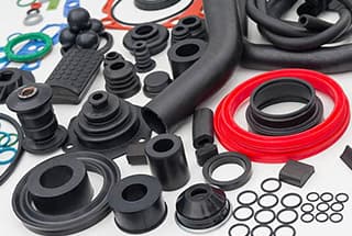
An O-ring is a type of rubber sealing ring that has a circular cross-section. It gets its name from its O-shaped cross-section, and is commonly referred to as an O-ring.
The O-ring was first introduced in the mid-19th century as a sealing element for steam engine cylinders. Today, it is widely used due to its affordability, ease of manufacture, reliable performance, and simple installation requirements. As a result, the O-ring is the most widely used design for mechanical sealing.
The O-ring can withstand high pressure, measured in tens of megapascals (kilopounds). It can be utilized in both static and dynamic applications where components move relative to each other, such as in rotating pump shafts and hydraulic cylinder pistons.
1. Overview
1.1 Characteristics of O-ring
An O-ring is a small ring-shaped sealing element that typically has a circular cross-section. The primary material used in its manufacture is synthetic molding compound, making it the most widely used type of seal in hydraulic engineering. It is mainly used for static and sliding seals.
Compared to other seals, the O-ring has several advantages, including:
a. Effective sealing and long service life
b. The ability to seal in both directions with a single ring
c. Good compatibility with oil, temperature and pressure
d. Low dynamic friction resistance
e. Small size, light weight and low cost
f. A simple and easily disassembled sealing structure
g. The ability to be used as either a static or dynamic seal
h. Standardized size and groove, making it convenient for selection and sourcing
One of the disadvantages of the O-ring is that when used as a dynamic seal, it has a large friction resistance, which is about 3 to 4 times greater than its dynamic friction. Additionally, it is prone to being squeezed into the barrier under high pressure.
1.2 Representation
1GB/T3452.1-1982 expression method
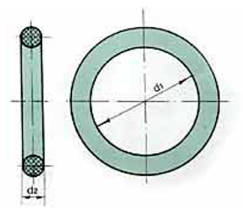
Inner diameter d1 × Wire diameter d2
For example:
O-ring 20 × 2.4 GB3452.1-82
The “20” indicates that the inner diameter of the O-ring is 20mm.
The “2.4” refers to the cross-sectional diameter of the O-ring, which is 2.4mm.
“GB3452.1” is the standard number.
“82” represents the year the standard was published.
24002000 GB3452.1-82
The “2400” represents the cross-sectional diameter of the O-ring, which is 2.4mm.
The “0200” indicates that the inner diameter of the O-ring is 20mm.
As in the first example, “GB3452.1” is the standard number and “82” represents the year the standard was published.
2. Representation of GB/T3452.1-2005
For example:
(1) O-ring 7.5 × 1.8G GB/T3452.1
The “7.5” indicates the inner diameter of the O-ring.
The “1.8” refers to the cross-sectional diameter of the O-ring.
The “G” series refers to the “Universal O-ring”. There are other series, such as “A” which stands for “O-ring for Aerospace”.
(2) A 0 × 0 × 7 × 5XG GB/T3452.1
The “A” series refers to the O-ring wire diameter of 1.80mm. There are other series with different wire diameters, such as:
“B” for O-ring wire diameter of 2.65mm
“C” for O-ring wire diameter of 3.55mm
“D” for O-ring wire diameter of 5.30mm
“E” for O-ring wire diameter of 7.30mm
2. Working state of O-ring seal
2.1 Function of O-ring for static seal
The O-ring is a type of extrusion seal. The basic principle of an extrusion seal is that it relies on the elastic deformation of the seal to create contact pressure on the sealing surface. If this contact pressure is greater than the internal pressure of the sealed medium, there will be no leakage, otherwise, leakage will occur. The process in which the medium itself changes the contact state of the O-ring to achieve sealing is referred to as “self sealing”.
Q-ring pre sealing
Self sealing effect:
Due to the pre-sealing effect, the O-ring is in close contact with both the sealed smooth surface and the bottom of the groove. As a result, when fluid enters the groove through a gap, it only acts on one side of the O-ring. When the fluid pressure is high, it pushes the O-ring to the other side of the groove and squeezes it into a D shape, transferring the pressure to the contact surface.
However, the self-sealing capability of O-rings is limited. When the internal pressure is too high, the O-ring may experience “rubber extrusion”. This occurs when there is a gap at the sealing point and high pressure causes stress concentration at the gap. When the stress reaches a certain level, the rubber will be squeezed out. Although the O-ring may temporarily maintain the seal, it has actually been damaged. Therefore, it is important to carefully select the appropriate O-ring for the application.
2.2 Function of O-ring for dynamic seal
In dynamic seals, the pre-sealing and self-sealing effects of the O-ring are similar to those in static seals. However, the situation is more complicated in dynamic seals due to the potential for fluid to be introduced between the O-ring and the rod during movement.
When the rod is in operation, if the left side of the O-ring is acted upon by medium pressure P1 (as shown in Figure a), the contact pressure generated by the O-ring on the rod is greater than P1 due to the self-sealing effect, ensuring a seal.
However, when the rod begins to move to the right, the medium attached to the rod is brought to the gap between the O-ring and the rod (Figure b). Due to the hydrodynamic effect, the pressure of this part of the medium is greater than P1 and may exceed the contact force of the O-ring on the rod, causing the medium to squeeze into the first groove of the O-ring (Figure c). As the rod continues to move to the right, the medium will continue to enter the next groove, resulting in leakage in the direction of the rod movement.
Leakage is less likely to occur when the rod moves to the left, as the driving direction is opposite to the pressure direction of the rod. The likelihood of leakage increases with the viscosity of the medium and the speed of the rod movement, as well as being closely related to the size and working pressure of the O-ring.
2.3 Sealing form of O-ring
O-ring seals can be categorized based on the relative motion between the seal and the sealed device:
Static seals
Reciprocating seals
Rotating seals
Switch seals
The compression (tightness) of the O-ring compression seal fit in the rectangular groove can be divided into five basic seal fits:
Compression fit
Sleeve tightening fit
Hydraulic fit
Pneumatic fit
Rotating fit
In addition, there is a squeeze seal fit in the chamfer groove of the end face, as well as two special sealing methods:
Sliding seal
Floating seal
The structure of the sealed parts can be used to categorize O-ring seals into the following types:
End seals, which include axial seals and angular seals (such as chamfer groove seals on the end surface of a hole or shaft)
Cylindrical seals, which include radial seals (such as cylindrical inner diameter seals for piston rods and cylindrical outer diameter seals for pistons)
Conical seals
Spherical seals.
3. Design and application of O-ring
3.1 Service parameters of O-ring
3.1.1 Compression ratio
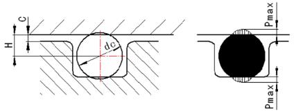
The compression ratio (W) of an O-ring is expressed as:
W = (d2 – h) / d2 × 100%
Where:
d2 – The cross-sectional diameter of the O-ring in its free state (mm)
h – The distance between the bottom of the O-ring groove and the sealed surface (groove depth), which is the cross-sectional height of the O-ring after compression (mm).
When choosing the compression ratio of an O-ring, it is important to consider the following factors:
Adequate sealing contact area
Minimal friction
Avoidance of permanent deformation
The selection of the compression ratio (W) should also take into account the service conditions and whether it is a static or dynamic seal.
Static seals can be further divided into radial seals and axial seals. The radial seals have radial clearances and the axial seals have axial clearances.
Axial seals can be further divided into internal pressure seals and external pressure seals, depending on whether the pressure medium acts on the inner diameter or outer diameter of the O-ring. Internal pressure increases the tension, while external pressure decreases the initial tension of the O-ring.
For these different forms of static seals, the direction of the sealing medium on the O-ring is different, so the pre-pressure design is also different.
For dynamic seals, it is important to distinguish between reciprocating seals and rotary seals.
Static seal: The cylindrical static seal device is similar to the reciprocating seal device and typically has a compression ratio of -10% to 15%. The plane static seal device has a compression ratio of -15% to 30%.
For dynamic seals, it can be divided into three cases: Reciprocating motion typically has a compression ratio of 10% to -15%.
When selecting the compression ratio for rotary motion seals, it is necessary to consider the Joule heat effect. Generally, the inner diameter of the O-ring used for rotary motion is 3% to 5% larger than the shaft diameter, and the compression ratio of the outer diameter is -3% to 8%.
For O-rings used in low friction applications, a small compression ratio of 5% to 8% is typically selected to reduce friction resistance. It is also important to consider the expansion of rubber materials due to the medium and temperature.
Typically, the maximum allowable expansion rate is 15% in addition to the given compression deformation. If this range is exceeded, it indicates that the material selection is inappropriate and either a different material for the O-ring should be used or the given compression deformation rate should be corrected.
3.1.2 Stretching amount
After the O-ring is installed into the sealing groove, it typically has a certain level of tension. This tension, like the compression ratio, greatly affects the sealing performance and lifespan of the O-ring. Excessive tension makes it difficult to install the O-ring and reduces the compression ratio, leading to leakage.
The stretching amount can be calculated using the following formula:
a = (d + d2) / (d1 + d2)
Where:
d – shaft diameter (mm) d1 – inner diameter of the O-ring (mm)
The recommended range for stretching amount is 1% to 5%. Table 1 provides the recommended stretching amount for O-rings, and the stretching amount can be selected and limited based on the shaft diameter size.
Table I limits of compression ratio and stretching amount of O-ring
Sealing form
Sealing medium
Stretching amount a (%)
Compression ratio w (%)
Static seal
Hydraulic oil
1.03~1.04
15~25
Air
<1.01
15~25
Reciprocating motion
Hydraulic oil
1.02
12~17
Air
<1.010.95~1
12~173~8
Rotational motion
Hydraulic oil
0.95~1
3~8
3.2 Installation groove of O-ring
The compression of an O-ring is primarily determined by the design and dimensions of the installation groove.
Rectangular and triangular grooves are the most commonly used shapes, with triangular grooves only being utilized for specific fixed seals.
The shapes of the grooves for static seals, reciprocating seals, and dynamic seals may be similar, but their sizes vary to accommodate differing compression requirements.
3.2.1 Slot width
The slot width is considered from the following three perspectives:
It must be larger than the maximum diameter of the O-ring after compression deformation.
The impact of motion-induced heating on the expansion and swelling of the O-ring must be taken into account.
Adequate space must be provided in the groove to allow for the O-ring to roll freely during reciprocating motion.
It is generally recommended that the cross-sectional area of the O-ring occupy at least 85% of the rectangular cross-sectional area. In many cases, the groove width is 1.5 times the cross-sectional diameter of the O-ring.
It is important to note that a narrow groove will increase friction and cause increased wear on the O-ring. On the other hand, if the groove is too wide, it will increase the O-ring’s range of movement and make it more susceptible to wear. Additionally, under static seals with pulsating pressure, the O-ring may experience pulsating movement and abnormal wear.
In high-pressure situations, a retaining ring must be used, and the groove width should be increased accordingly.
3.2.2 Groove depth
The depth of the groove is a crucial factor for the proper functioning of the O-ring. It mainly depends on the compression deformation of the O-ring.
This deformation is composed of the compression deformation (A1) at the inner diameter of the O-ring and the compression deformation (A2) at the outer diameter of the O-ring.
When A1=A2, the cross-section of the O-ring coincides with the center of the groove cross-section, and the two circles are equal, indicating that the O-ring is not stretched during installation.
When A1>A2, the circumference of the O-ring section center is smaller than that of the groove center, indicating that the O-ring is installed in a stretched state.
When A1<A2, the perimeter of the O-ring section is greater than the center perimeter of the groove section. In this case, the O-ring is installed with circumferential compression, and it will bounce during disassembly.
When designing the groove depth, the intended use of the O-ring should be considered first, followed by the selection of a reasonable compression deformation rate. The swelling of the material in the medium, the swelling of the material itself, and other related factors should also be taken into account.
However, there are relevant standards provided by the state for the structure of grooves.
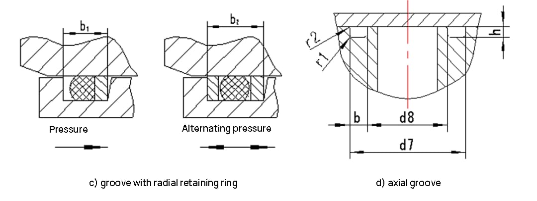
3.2.3 Selection and design of grooves
1. Installation form of groove
Explain:
To prevent the O-ring from being damaged by being compressed into a gap, it is generally recommended to secure the seal when the liquid working pressure exceeds 10MPa. If the liquid pressure exceeds 32MPa, a sealing ring should be added (as shown in Fig. c). The number of rings depends on the pressure of the O-ring.
When there is external pressure applied on the axial seal, it is important to add a boss at diameter d8 to prevent the O-ring from entering the pipeline.
Table II Radial groove size of O-ring
O-ring section diameter d2
1.80
2.65
3.55
5.30
7.00
trench width
Pneumatic seal
2.2
3.4
4.6
6.9
9.3
Hydraulic dynamic seal or static seal
b+0.25
2.4
3.6
4.8
7.1
9.59.5
b1+0.25
3.8
5.0
6.2
9.0
12.3
b2+0.25
5.2
6.4
7.6
10.9
15.1
Groove depth t
Piston rod seal, (for calculation d3)
Hydraulic dynamic seal
1.42
2.16
2.96
4.48
5.95
Pneumatic seal
1.46
2.23
3.03
4.65
6.20
Static seal
1.38
2.07
2.74
4.19
5.67
Piston rod seal, (for calculation d6)
Hydraulic dynamic seal
1.47
2.24
3.07
4.66
6.16
Pneumatic seal
1.57
2.37
3.24
4.86
6.43
Static seal
1.42
2.15
2.85
4.36
5.89
Minimum chamfer length Zmin
1.1
1.5
1.8
2.7
3.6
Groove bottom fillet radius r1
0.2-0.4
0.4-0.8
0.8-1.2
Groove fillet radius r2
0.1-0.3
Maximum diameter of piston rod seal groove bottom d3max=d4+2t, d4 piston rod diameter
The minimum diameter of piston rod seal groove bottom d6min=d5max+2t, d5max piston rod maximum diameter.
China has established standards for the groove size series of O-rings. The details can be found in Table 3.
Table III groove size and compression for sealing
0-ring section dimension tolerance
1.9±0.08
2.4±0.08
3.1±0.10
3.5±0.10
5.7±0.15
8.6±0.16
Axial fixed seal
Compression amount
0.60~0.40
0.70~0.504
0.85~0.55
0.90~0.65
1.3~0.9
1.6~1.0
Groove size
h
1.3~1.5
1.7~1.9
2.25~2.55
2.60~2.85
4.40~4.80
7.00~2.60
b
2.50
3.20
4.2
4.70
7.50
11.2
r≤
0.40
0.7
0.80
For sports
Compression amount
0.47~0.28
0.47~0.27
0.54~0.30
0.60~0.324
0.85~0.45
1.06~0.68
Groove size
h
1.43~1.62
1.93~2.13
2.65~2.80
2.90~3.18
4.85~5.25
7.54~7.92
b
Without retaining ring
2.5
3.2
4.2
4.70
7.5
11.2
Add a retaining ring
3.9
4.4
5.2
6.0
9.0
13.2
Add two retaining rings
5.40
6.0
7.0
7.8
11.5
17.2
r≤
0.4
0.7
0.8
Note: h refers to the height of the groove; b represents the width of the trench; r refers to the chamfer of the groove.
3. O-ring groove processing requirements
To prevent leakage due to scratches and improper installation, there are certain requirements for the accuracy of grooves and related components when installing O-rings.
First, the edges passing through during installation must be blunt or rounded, and the inner hole passing through should be chamfered at a 10-20 degree angle.
Second, the surface accuracy along the O-ring’s installation path must be carefully considered. The shaft must have a low roughness value and be lubricated if necessary.
The requirements for installation groove and matching surface accuracy can be found in Table IV.
Table IV Surface finish of mating parts of O-shaped rubber seal groove
surface
Applications
Pressure condition.
Surface finish
Bottom and sides of trench
Tight seal
Non alternating and non pulse,
R.3.2um
Alternating or pulse,
R.1.6um
Dynamic seal,
Non alternating and non pulse.
Mating surface
Tight seal
Non alternating and non pulse.
R.1.6um.
Alternating or pulse,
R.0.8um
Dynamic seal
R0.4 μ m
3.3 Material selection of O-ring
The selection of O-ring material takes into account the following factors:
The working state of the O-ring, such as whether it is used for static sealing, dynamic sealing, or sliding sealing.
The operating state of the machine, including whether it works continuously or intermittently, and the length of each interruption, and its impact on the sealing component.
The working medium, whether it is gas or liquid, and its physical and chemical properties.
The working pressure, including pressure magnitude, fluctuation amplitude, frequency, and the maximum instantaneous pressure.
The working temperature, including the instantaneous temperature and the alternating temperature of hot and cold.
The cost and availability.
Typically, nitrile rubber is used for oil resistance, chloroprene rubber for weather resistance and ozone resistance, acrylate rubber or chlorine rubber for heat resistance, polyurethane rubber for high pressure resistance and wear resistance, and copolyazole rubber for cold resistance and oil resistance.
The scope of application for various adhesives can be found in Table 5.
Table V Specification for use of O-ring sealing materials
Material Science
Applicable media
Service temperature / ℃
Remarks
For sports
Static use
Nitrile rubber
Mineral oil, gasoline, benzene
80
-30~120
Neoprene
Air, water, oxygen
80
-40~120
Precautions for sports
butyl rubber
Animal and vegetable oil, weak acid, alkali
80
-30~110
Large permanent deformation, not suitable for mineral oil
butadiene styrene rubber
Alkali, animal and vegetable oil, air, water
80
-30~100
Not applicable to mineral oil
Natural rubber
Water, weak acid, weak base
60
-30~90
Not applicable to mineral oil
silicon rubber
High and low temperature oil, mineral oil, animal and vegetable oil, oxygen, weak acid, weak base
-60~260
-60~260
Not suitable for steam, avoid using in moving parts
As the founder of MachineMFG, I have dedicated over a decade of my career to the metalworking industry. My extensive experience has allowed me to become an expert in the fields of sheet metal fabrication, machining, mechanical engineering, and machine tools for metals. I am constantly thinking, reading, and writing about these subjects, constantly striving to stay at the forefront of my field. Let my knowledge and expertise be an asset to your business.
What if the future of engineering isn't just about innovative designs, but groundbreaking materials? From optical fibers revolutionizing data transmission to superconductive materials enhancing energy efficiency, the latest advancements in…
Have you ever thought about the hidden strength behind the bolts holding our world together? This article explores the fascinating world of bolt weights and strength grades, revealing how these…
How do you keep crucial lubricants from leaking and causing damage in machinery? Skeleton oil seals might just be the unsung heroes of industrial maintenance. These seals play a vital…
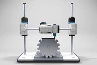
What makes intricate designs possible in 3D printing? The answer lies in support structures. This article explores the necessity, types, and design strategies of support structures that prevent part deformation…
1. What are the factors affecting the fatigue strength of bolts? There are various factors that can impact the fatigue strength of a connection, including the material used, structural design,…
What makes a material suitable for a specific engineering application? The answer lies in understanding its properties. This article covers 11 essential material properties, such as mechanical strength, impact toughness,…
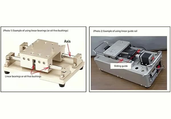
Have you ever wondered what the key to smooth, precise motion is in machines? Linear bearings are the unsung heroes behind countless automated systems, enabling effortless transfer, handling, positioning, and…
Imagine creating anything you want, layer by layer, right at your desk. Welcome to the world of 3D printing! This revolutionary technology, also known as additive manufacturing, builds objects by…
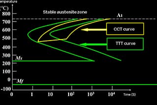
How does the cooling rate affect the microstructure of steel? The C-curve in heat treatment reveals the fascinating transformation of carbon steel's microstructure during cooling. This article delves into the…