Motor Bearing Heat Generation: A Complete Analysis
Why do motor bearings get so hot, and what can be done about it? This article dives into the causes of motor bearing heat generation, from excessive loads and poor…
Are you tired of inverter failures disrupting your operations? In this blog post, we’ll dive into the world of inverter troubleshooting, guided by the insights of a seasoned mechanical engineering expert. Discover the secrets to identifying and resolving common inverter faults, from minor glitches to major breakdowns. Arm yourself with the knowledge to keep your inverters running smoothly and efficiently. Get ready to master the art of inverter troubleshooting and take control of your machinery’s performance!
GUIDE
Inverters, which convert direct current (DC) to alternating current (AC), are critical components in various applications, including renewable energy systems, uninterruptible power supplies (UPS), and industrial motor drives. However, like any electronic device, inverters can experience faults.
What are the common faults in inverters? How can one differentiate between major and minor faults?
Let’s examine the causes of inverter failures and 32 methods for remediation.
In the event of a minor fault, the system will issue an alarm signal and the fault indicator will flash.
In the case of a significant fault, the system will issue a fault indication, and the fault indicator will remain lit.
Simultaneously, a command will be issued to disconnect the high voltage and prevent it from being reconnected. The fault information and the high voltage disconnect command will be recorded for future reference.
The severe fault condition will not be cleared, and the fault indication and high voltage disconnect command will remain in effect.
Minor faults include: transformer overheating alarm, cabinet overheating alarm, cabinet door opening, unit bypass. The system does not store records of minor faults, only displays the fault indication. The alarm will be automatically cleared once the fault is resolved.
If a minor fault alarm occurs during inverter operation, the system will not shut down.
If a minor fault alarm occurs during shutdown, the inverter can still start up normally.
When the following faults occur in the system, they are treated as major faults and the type of major fault will be displayed in the upper left corner of the monitor.
These faults include external faults, transformer overheating, cabinet temperature overheating, unit faults, inverter over-current, high voltage power loss, interface board failure, controller communication failure, interface board communication failure, motor overload, parameter error, and main control board failure.
Unit faults include fuse failure, unit overheating, drive failure, fiber failure, and unit over-voltage.
For external faults, the high-voltage break state (cabinet door button or external contact) must be cleared before the system can be reset and return to normal operation.
For major faults other than external faults, a direct system reset can restore normal operation, but the root cause of the fault must be identified before powering on again.
Unit faults can only be detected when high voltage power is restored.
If the fault is difficult to diagnose and it is uncertain whether secondary high voltage can be applied, please consult the manufacturer.
Note: Do not power on the inverter twice without identifying the cause of the failure, as it could result in serious damage to the inverter.
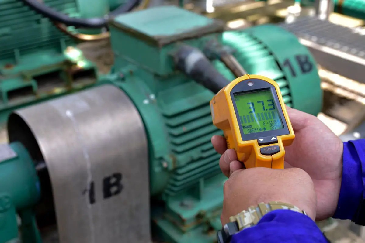
Check if the temperature displayed by the thermostat is above 130 degrees. If not, verify if the over-temperature alarm value for the thermostat has been set to 130 degrees. For further checks, refer to the section on the transformer over-temperature alarm.
When the temperature of the unit cabinet’s measurement point exceeds 60°C, the system will report a severe cabinet temperature overheating failure. For inspection items, refer to the cabinet temperature over-temperature alarm.
Check if the ‘pre-travel’ and ‘over-travel’ settings of the travel switch are appropriate and if the electrical function of the travel switch is functioning correctly. If not, replace the interface board.
Ensure that the communication cable connecting the monitor control board to the main control board is properly connected, and verify that the +15V and +5V readings on the monitor control board are accurate.
In case of issues, consider replacing the main control panel or the monitor.
The monitor detects a fault in the main control board and reports it as such if it has established communication with the controller. To resolve the issue, replace the monitor or the main control panel.
The monitor does not establish communication with the interface board, which will reset every 5 seconds.
If the monitor, at 3 minutes and 30 seconds, does not establish communication, it will be judged as a heavy failure.
If an incorrect parameter is set during parameter modification (this fault may occur during synchronous vector control), a parameter error fault is reported. To resolve this, please modify the parameters again and press the reset button.
When the local high-voltage disconnect button is pressed or the high-voltage disconnect junction on the interface board is closed, the system will report an external fault. Check if the high-voltage disconnect button is pressed, if the high-voltage disconnect terminal is shorted, or if the interface is faulty.
Typically caused by normal gate operation.
If there is an abnormally high voltage power failure (no fault recorded, no switchgear operation), please check the circuit opening of the superior switch cabinet.
When the inverter’s output current exceeds 1.5 times its rated current, the inverter will activate its over-current protection. To troubleshoot, consider the following:
To eliminate the over-current protection, check the relevant devices and eliminate the possible causes of the issue:
Note: In some cases, the motor low-speed current fluctuation can cause repeated acceleration, deceleration, and over-current protection due to the tooth groove effect. In such cases, reducing the acceleration time and increasing the current limiting factor can help the motor pass quickly through the fluctuating area and avoid over-current protection.
The inverter’s output current is 1.2 times greater than the rated motor current and continues for over 2 minutes.
Please check if the parameter setting for the motor’s rated current is correct. Also, check if the motor or load machinery is blocked and if the power supply voltage is too low.
Check the output of the inverter for contactors or switch-type equipment. Ensure that the primary output cable of the inverter is connected to the motor. Observe the monitor for output current and voltage. If there is voltage but no current, it means the inverter to the main circuit of the motor is open. If there is both voltage and current, check if the cable has a single-phase ground or if the motor rotor winding is open.
There are five types of unit failures, including fuse failure, drive failure, unit overheating, unit over-voltage, and fiber optic failure. The first three types of failures can be bypassed if the unit has a bypass function and the bypass level is set to non-zero when it is valid.
Please check if it is caused by the mains power outage; if the three-phase incoming wires of the unit are loose; if the incoming fuse is intact. If the fuse is open, replace the unit.
Check if the voltage detection board of the unit is short-circuited. If it is, it will result in the A1, B1, and C1 units reporting a drive failure.
Check if the output L1 and L2 of the power unit are shorted. If not, the IGBT of the unit may be damaged. Please replace the unit in this case.
Verify that the insulation of the motor is in good condition.
Inspect for any mechanical failure in the load.
There is a temperature switch (normally closed point) located on the unit’s radiator. If the temperature exceeds 85℃, the temperature relay’s normally closed point will be disconnected, causing the unit to report an overheating fault.
To troubleshoot the issue, check if the overhead fan is functioning properly, if the unit cabinet fan switch has tripped, and if the filter screen is blocked (you can test this by placing a piece of A4 paper on the filter screen and checking if it can be adsorbed. If it can’t, you’ll need to clean the filter screen).
Consider if the unit is working in a long-term overload condition or if the ambient temperature is too high (the ambient temperature should be below 45℃. If it’s not, you may need to improve ventilation with a wall-mounted ventilator, roof-mounted air duct, or by installing refrigeration equipment).
Check if the unit control board is faulty, and finally, verify that the power unit temperature relay is functioning normally.
The DC bus voltage has exceeded the protection value, causing the inverter to alarm for an over-voltage unit.
When the inverter is in operation, a low output voltage from a unit can lead to a three-phase output imbalance, resulting in an over-voltage unit alarm.
During the commissioning of a no-load motor, it is common for the DC bus to experience over-voltage and for units A1/B1/C1 to report over-voltage. In this case, it may be appropriate to lower the reference voltage.
Verify that the input high voltage power supply does not exceed the permissible maximum. If the supply voltage is too high, consider adjusting the transformer taps to 105%.
If over-voltage occurs during deceleration, consider increasing the deceleration time setting of the inverter to mitigate the issue.
When the system fails to detect unit communication during power-up, it reports a fiber optic failure.
Please check if the power unit control power supply is functioning normally (indicated by a green light). If it’s not, replace the power unit. Also, ensure that the fiber optic connector between the power unit and the controller is not disconnected, and check if the fiber optic cable is broken.
The unit is equipped with bypass hardware and the bypass level parameter setting is non-zero. If the unit experiences drive failure, fuse failure, or overheating, the unit will bypass these three failures.
In the event of a failure in one unit, causing it to bypass, the other two units in the same position will also bypass.
Even though the inverter can still start and operate during a unit bypass, the rated output voltage and capacity will be reduced due to the decreased number of units per phase in series.
It is important to promptly identify and rectify the cause of a unit bypass and replace the faulty unit. The remaining two bypassed units do not need to be replaced.
Regular cleaning of the unit’s drive board and control board is important, as a buildup of dust on these boards may cause false alarms.
There are several reasons for the situation where the frequency inverter is unable to stop at a numerical point. These reasons include the limitations imposed by the acceleration and deceleration time in the acceleration and deceleration process, and the need for the output frequency to reach a specified frequency.
When the system voltage is too high, the frequency inverter may not be able to stop at a numerical point in order to avoid triggering the DC bus over-voltage protection for its own protection. In such cases, it is recommended to connect the transformer taps to 105%.
Additionally, if the output current of the inverter exceeds the set current limit value, the inverter will automatically reduce the frequency in order to reduce the output current and avoid triggering the over-current protection. This can occur when the input voltage is too low or when there is a sudden increase in the load, a transient power failure, a failure of a hall element, unit detection board, or signal board, or when the inverter needs to slow down in order to obtain energy from the motor in order to maintain control.
To resolve the issue, press the system reset button located on the cabinet door. Note that resetting the system will not affect the normal operation of the inverter. If the problem persists, inspect the power terminal of the monitor for disconnection, check if the connection cable is loose, verify if the 5V and 15V power supply is functioning normally, and look for any obvious damage to the monitor’s wiring. If interference is identified, replace the monitor.
When the parameter modification option is disabled in the function parameter, only the given frequency or the given parameter can be modified, all other parameters are locked.
It is not possible to change most of the parameters while the system is in operation.
In remote control mode, the start and stop functions can only be performed through the remote terminal. If the start mode in the parameter setting is level start (with closed start and disconnected stop), the inverter will stop immediately if the emergency stop signal is disconnected during operation or if it is stopped by other means.
However, when the emergency stop signal is closed again and the remote start level signal remains present, the inverter will automatically start running.
When the inverter is powered on, the magnetic surge from the transformer and the charging of the unit capacitors can cause the instantaneous RMS current to reach up to 6-7 times the rated current of the inverter for a duration of several tens of milliseconds.
If the upper stage current protection setting value of the inverter is set too low, it can trigger the upper stage switch’s quick break protection. To resolve this issue, the upper-level switchgear quick break protection setting must be adjusted.
Some motors at low speed experience significant fluctuations in current due to the slot effect, causing the inverter to experience repeated acceleration, current limit deceleration, and other issues, instead of normal acceleration.
To resolve this issue, you need to increase the current limit setting, shorten the start-up time, and replace the unit if the output voltage is low.
Check if the time-delay time-absorbing relay in the bypass cabinet is set between 1.5 seconds and 3 seconds. Ensure that the switchgear calibration value is not too small (it should be more than five times the motor’s rated current). Set the quick-break protection time of the switchgear to greater than 0.1 seconds.
It may be due to a remote start/stop, high voltage break, or system reset signal line sensing voltage. It is recommended to wire the passive signal separately from the 220V AC power supply, using a shield wire that is grounded at both ends.
It could also be due to induced voltage from the signal cable on the remote control box and the power supply cable being tied together. To resolve this issue, it is recommended to rewire the signal in the remote control box, using a shield wire for the signal without any sharp edges and making sure the shield wire stripping is not too long.
For the 4-20mA current signal, an AC induced voltage (below 10V) may be present, which can be connected between the current signal and ground with a 275V/0.33uf capacitor.

As the founder of MachineMFG, I have dedicated over a decade of my career to the metalworking industry. My extensive experience has allowed me to become an expert in the fields of sheet metal fabrication, machining, mechanical engineering, and machine tools for metals. I am constantly thinking, reading, and writing about these subjects, constantly striving to stay at the forefront of my field. Let my knowledge and expertise be an asset to your business.