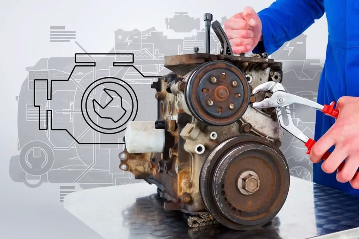
The causes of mechanical equipment failures stem from a variety of sources; some are due to inherent defects in the equipment itself, while others are related to design issues, such as unreasonable original design structure, dimensions, coordination, and material selection. There are also issues with the defects of the part materials, such as uneven material quality, excessive internal residual stress, and so on.
Manufacturing problems, such as technical issues in mechanical processing, casting, forging, heat treatment, assembly, and standard parts during the manufacturing process, also contribute to failures. Furthermore, assembly issues, such as improper selection and adjustment of parts as well as incorrect installation, can lead to problems. Lastly, issues in inspection and testing can also cause equipment failures.
I. Failure of Mechanical Parts
(1) Classification of Mechanical Part Failures
A mechanical part is considered to have failed when it loses its specified function. A part is deemed to have failed if it falls into one of the following two states: it cannot complete its specified function, or it cannot be reliably and safely continued in use.
Part failure is the primary cause of mechanical equipment breakdowns. Therefore, studying the failure patterns of parts, identifying the causes of their failures, and adopting improvement measures are of great significance to reduce the occurrence of mechanical failures and prolong the service life of machinery.
The main manifestation of mechanical part failure is the wear and tear of the working mating surfaces of the parts, which accounts for the largest proportion of part damage. Material corrosion and aging are another inevitable type of failure during the working process of parts, but their proportion is generally much smaller. These two forms of failure essentially summarize the main failure modes of mechanical parts under normal use conditions.
Other forms of failure, such as fatigue fracture and deformation of parts, although frequently occurring in practice and considered the most dangerous forms of failure, are mostly due to manufacturing and design defects, or improper maintenance and use of machinery.
Failure analysis refers to the investigation and study of the characteristics and rules of phenomena or processes such as wear, fracture, deformation, and corrosion of parts, in order to identify the main causes of failure and adopt appropriate control methods.
The purpose of failure analysis is to provide a reliable basis for the formulation of repair technical schemes, and to control certain factors causing failure, in order to reduce equipment failure rates and prolong equipment service life.
In addition, failure analysis can also provide feedback information for equipment design and manufacturing, and provide objective evidence for equipment accident identification.
(2) Component Wear
1) Wear Pattern of Components
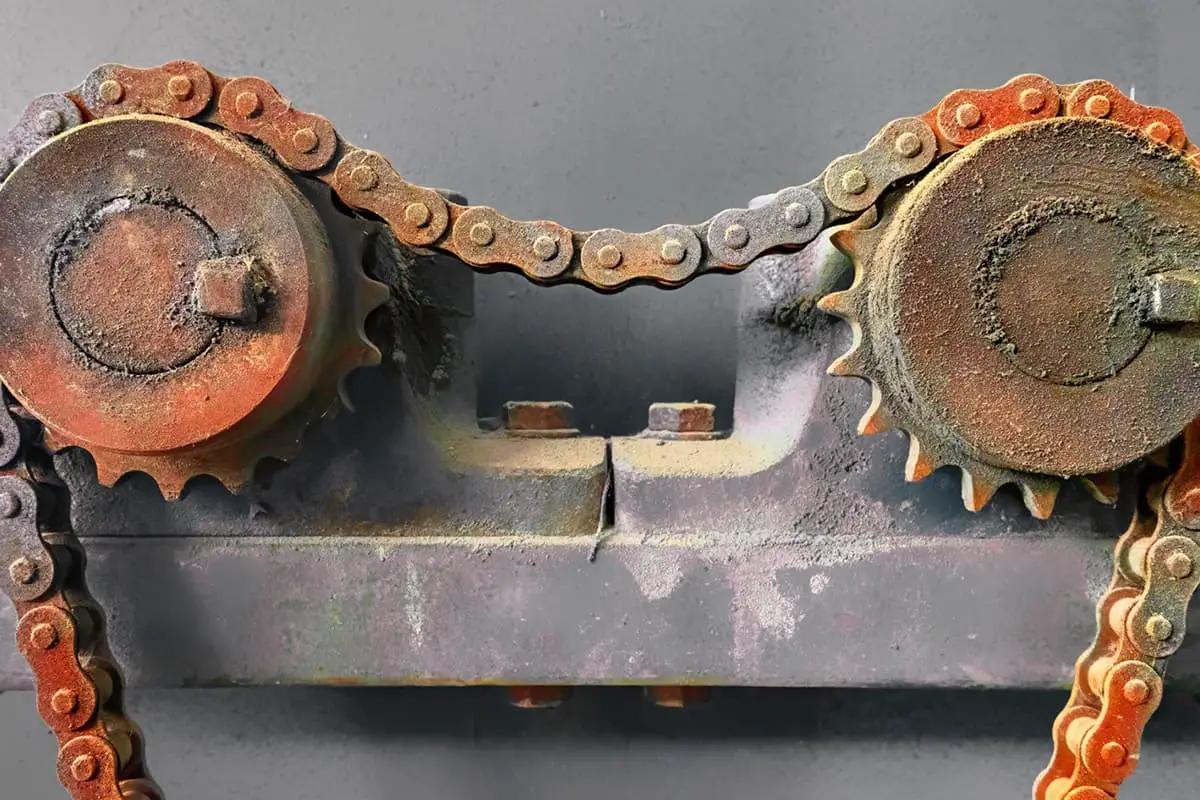
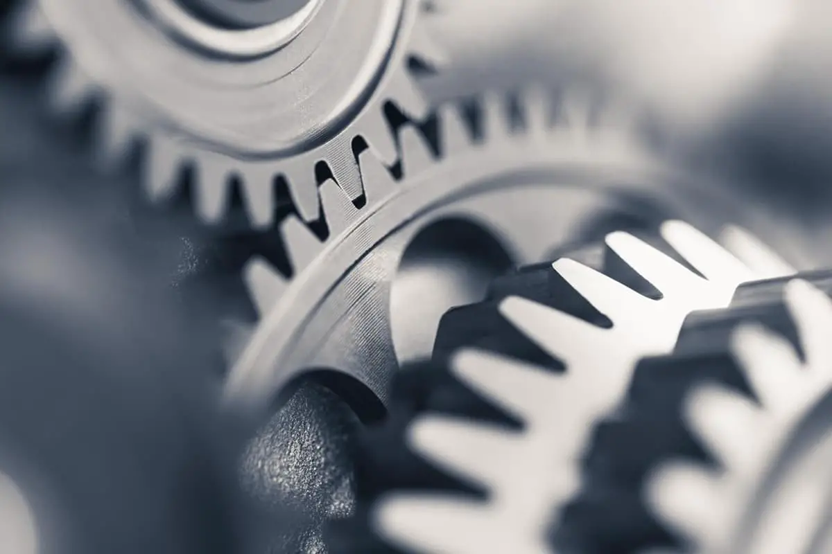
It is well-known that fundamental units like parts and components constitute machinery such as cars and tractors. Friction pairs made up of many parts, such as bearings, gears, and piston-cylinder assemblies, experience certain friction and wear until they finally fail under the influence of external forces and environmental factors like heat and chemicals.
Among all mechanical failures, wear-related faults account for a significant proportion. Therefore, understanding the wear patterns of components and their matching pairs is essential.
a) Typical Wear Curve of Components
Wear is a type of progressive fault. For instance, the faults caused by cylinder wear differ from abrupt faults like fan belt rupture or capacitor breakdown, the latter being sudden faults, while the faults caused by wear are attritional faults.
b) Permissible Wear and Limit Wear
2) Abrasive Wear
Also known as particle wear, abrasive wear occurs when hard particles exist between the contact surfaces of friction pairs, or when the hardness of one side’s material is significantly higher than the other, resulting in a wear phenomenon similar to metal cutting.
It is a type of mechanical wear characterized by visible cutting marks on the contact surface. Among all types of wear, abrasive wear accounts for approximately 50%, making it the most common and damaging form of wear.
Its wear rate and intensity are high, significantly reducing the lifespan of mechanical equipment and resulting in considerable energy and material consumption.
Depending on the stress and impact the friction surface undergoes, abrasive wear can be further divided into three types: chisel-cutting style, high-stress grinding style, and low-stress scratching style.
a) Mechanism of Abrasive Wear
The mechanical action of abrasive particles involves two processes: one is the micro-cutting process along the friction surface by the abrasive particles; the other is the alternating contact stress on the surface layer caused by the particles, leading to constantly changing dense impressions on the surface layer, and ultimately erosion due to surface fatigue.
Sources of abrasive particles include external dust and sand, chip intrusion, fluid carry-in, surface wear debris, surface hard points of material structure, and inclusions. A notable feature of abrasive wear is that the wear surface has tiny grooves parallel to the direction of relative motion, with spiral, circular, or curved tiny chips and some powder.
b) Measures to Reduce Abrasive Wear
Abrasive wear is caused by the mechanical action of abrasive particles on the surface of the friction pair. Therefore, strategies to reduce or eliminate abrasive wear can be approached from the following two aspects.
i) Reduce the Entry of Abrasives
Prevent external abrasives from entering friction pairs in mechanical equipment and promptly clear the chips produced during the running-in process.
Specific measures include the installation of air filters and fuel/oil filters, adding dustproof sealing devices, installing magnetite, chip collection rooms, and oil contamination indicators in the lubrication system, and regularly cleaning and replacing air, fuel, and oil filtration devices.
ii) Enhance the Wear Resistance of Component Surfaces
Firstly, materials with good wear resistance can be selected.
Secondly, for components that require wear resistance and are subject to impact loads, heat treatment and surface treatment can be used to improve the properties of the component material surface, enhance surface hardness, and strive to exceed the hardness of the abrasive.
Thirdly, for components with less stringent precision requirements, wear-resistant alloys can be welded onto the working surface to improve wear resistance.
3) Adhesive Wear
Adhesive wear refers to the type of wear caused by the transfer of material from one friction surface to another during relative movement. Depending on the degree of damage on the surface of the friction pair, adhesive wear can be categorized into five types: minor wear, smearing, scuffing, tearing, and seizure.
① Mechanism of Adhesive Wear
When the friction pair operates under heavy load conditions, heat generated from poor lubrication, high relative movement speed, and friction can’t dissipate quickly enough, leading to extremely high surface temperatures.
In severe cases, the surface layer of the metal may soften or melt, reducing the surface strength. The high-pressure surface protrusions adhere to each other and are subsequently torn off during relative movement. This causes material to transfer from the weaker surface to the stronger surface, leading to catastrophic damage to the friction pair, such as seizure or scratching.
② Measures to Reduce Adhesive Wear
a. Control the Surface Condition of the Friction Pair
The cleaner and smoother the friction surface, the more likely adhesive wear is to occur, especially if the surface roughness is overly small. Metal surfaces often have adsorbed films that can be disrupted by plastic deformation or temperature increases of 100-200℃, both of which can lead to adhesive wear.
To reduce adhesive wear, an appropriate lubricant should be chosen based on load, temperature, speed, and other working conditions.
Additives may also be added to the lubricant to establish necessary lubrication conditions. The oxygen in the atmosphere can form a protective oxide film on the metal surface, preventing direct metal contact and adhesion, reducing friction and wear.
b. Control the Material Composition and Microstructure of the Friction Pair Surface
Adhesive wear is most likely to occur between two metal materials with similar material compositions and microstructures, due to their strong tendency to form solid solutions or intermetallic compounds.
Therefore, the materials of the friction pair should be those with the least tendency to form solid solutions, meaning they should have different material compositions and crystal structures.
Covering one surface of the friction pair with metals like lead, tin, silver, or copper, or soft alloys, can increase resistance to adhesive wear. The use of materials like Babbitt metal or aluminum bronze as the surface material of bearing liners can improve their resistance to adhesive wear. Steel and cast iron pairings also perform well against adhesive wear.
c. Improve Heat Transfer Conditions
By selecting materials with good thermal conductivity and cooling the friction pair or taking appropriate heat dissipation measures, the temperature during the relative movement of the friction pair can be lowered, maintaining the strength of the friction pair surface.
4) Fatigue Wear
Fatigue wear refers to the phenomenon where microscopic particles of a material fall off due to fatigue cracks formed under cyclic contact stress on localized areas of the friction pair surface. Depending on the contact and relative motion between the friction pairs, fatigue wear can be divided into rolling contact fatigue wear and sliding contact fatigue wear.
① Mechanism of Fatigue Wear
The process of fatigue wear is the destructive process of crack formation and expansion, and the formation and shedding of microscopic particles. Abrasive wear and adhesive wear are related to direct contact with the friction pair surface. If a lubricant separates the two friction surfaces, these two wear mechanisms do not function.
For fatigue wear, even if there is a lubricant between the friction surfaces and they do not directly contact, it can still occur due to the stress transmitted through the lubricating oil film.
Unlike abrasive wear and adhesive wear, fatigue wear does not occur immediately, but after a certain number of stress cycles, microscopic particles fall off, causing the friction pair to lose its working ability. The mechanisms of fatigue wear can be divided into the following two cases based on the location of crack formation.
a. Rolling Contact Fatigue Wear
The occurrence of varying depth spiny or pock-marked pits (depth below 0.1-0.2mm) or larger area particle shedding on the surface of relative rolling friction pairs, such as rolling bearings and transmission gears, is caused by rolling contact fatigue wear, also known as pitting or spalling wear.
b. Sliding Contact Fatigue Wear
For two sliding contact objects, the shear stress is at its maximum at a depth of 0.786b below the surface (b is half the width of the plane contact area), where plastic deformation is the most severe. Repeated deformation under cyclical loads will weaken local strength on the material surface and cracks will first appear here.
The combined action of shear stress caused by sliding friction and normal load shifts the maximum shear stress from 0.786b to a deeper surface, resulting in sliding fatigue wear. The depth of the peeled layer is typically 0.2-0.4mm.
② Strategies to Reduce or Eliminate Fatigue Wear
The strategies to reduce or eliminate fatigue wear involve controlling the factors affecting crack formation and expansion, mainly in the following two aspects.
a. Proper Selection of Material and Heat Treatment
The presence of non-metallic inclusions in steel can easily cause stress concentration, and the edges of these inclusions are most likely to form cracks, thereby reducing the contact fatigue life of the material. The material’s microstructure and internal defects also greatly affect wear.
Generally, small, uniform grains and spherically distributed carbides improve the rolling contact fatigue life. When the carbon content in martensite is around 0.4%-0.5% under the same conditions of undissolved carbides, the material’s strength and toughness are well-balanced, and the contact fatigue life is high.
For undissolved carbides, appropriate heat treatment to make them less, finer, and evenly distributed can help eliminate fatigue cracks. Hardness increases within a certain range will also increase the resistance to contact fatigue.
For instance, bearing steel surface hardness is at its maximum anti-fatigue wear ability at around 62HRC. For gear teeth, a hardness range of 58-62HRC is optimal.
Moreover, matching hardness between two contact rolling bodies is also important. For instance, in rolling bearings, it’s appropriate for the raceway and rolling element to have similar hardness, or for the rolling element to be about 10% harder than the raceway.
b. Proper Selection of Surface Roughness
Experience shows that appropriately reducing surface roughness is an effective way to improve anti-fatigue wear ability. For instance, when the surface roughness of a rolling bearing is reduced from Ra 0.40μm to Ra 0.20μm, its life can be increased 2-3 times; when reduced from Ra 0.20μm to Ra 0.10μm, the life can be doubled.
However, reducing it below Ra 0.05μm has little impact on life extension. The requirement for surface roughness is related to the contact stress on the surface. Usually, when the contact stress is high or surface hardness is high, a smaller surface roughness value is required.
In addition, the state of surface stress, the degree of fitting accuracy, and the nature of the lubricating oil can all affect the rate of fatigue wear. Typically, excessive surface stress, too small or too large fitting clearances, or corrosive substances produced by the lubricating oil during use can all exacerbate fatigue wear.
5) Corrosive Wear
① Mechanism of Corrosive Wear
During the friction process, metals simultaneously react chemically or electrochemically with the surrounding medium, causing the formation and detachment of corrosion products on the metal surface. This phenomenon is referred to as corrosive wear.
It is a wear phenomenon formed by the combination of corrosion and mechanical wear, so its mechanism differs from those of abrasive wear, adhesive wear, and fatigue wear. It is an extremely complex wear process that frequently occurs in high-temperature or humid environments and is more likely to occur under conditions with special media such as acids, alkalis, and salts.
Depending on the corrosive medium and the properties of the material, corrosive wear is generally divided into two categories: oxidation wear and corrosive wear in special media.
a. Oxidation Wear
This type of wear, known as oxidation wear, occurs when the oxide film formed on the friction surface due to the action of oxygen in the air or lubricant is quickly removed by mechanical friction. The vast majority of metals used in industry can form a surface oxide film when oxidized, and the properties of these oxide films have a significant impact on wear.
If a dense, intact oxide film that is firmly bonded to the substrate is formed on the metal surface, and the film has good wear resistance, the wear will be minor.
However, if the film’s wear resistance is poor, the wear will be severe. For instance, both aluminum and stainless steel easily form an oxide film, but the wear resistance of the oxide film on the surface of aluminum is poor, while that of stainless steel is good, therefore, stainless steel has a stronger oxidation wear resistance than aluminum.
b. Corrosive Wear in Special Media
The wear form in which the corrosion products formed on the friction surface due to the action of electrolytes such as acids and alkalis in the environment are quickly removed by mechanical friction is referred to as corrosive wear in special media.
The mechanism of this wear is similar to that of oxidation wear, but its wear rate is much higher. The nature of the medium, environmental temperature, the strength of corrosion products, adhesion, and other factors all have a significant impact on the wear rate.
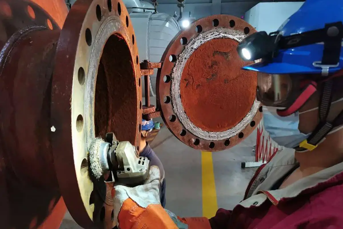
This type of corrosive wear is very likely to occur, such as in fluid transport pumps, which when transporting corrosive fluids, especially fluids containing solid particles, all parts in contact with the fluid will be subjected to corrosive wear.
② Measures to Reduce Corrosive Wear
a. Choosing the right material and applying antioxidation treatment to the surface. Steel containing elements such as chromium, nickel, molybdenum, and tungsten can be selected to enhance the oxidation wear resistance of the friction surface.
Alternatively, strengthening treatments such as shot peening and roll-pressing, or anodic treatment, can be applied to the friction surface to form a dense structure or oxide film on the metal surface, thereby improving its oxidation wear resistance.
b. For corrosive wear under the action of specific media, the wear rate can be reduced by controlling the formation conditions of the corrosive medium, selecting suitable wear-resistant materials, and changing the way the corrosive medium acts.
6) Fretting Wear
Fretting wear, which occurs when two fixed contact surfaces experience minor amplitude vibrations, mainly manifests on relatively stationary component interfaces, such as key connection surfaces, interference or transition fit surfaces, or surfaces connected by bolts or rivets on the machine body. As such, it is often overlooked.
The primary risk of fretting wear is a decrease in fitting precision, along with a reduction in the interference of interference-fitted parts and even loosening. It could lead to loosening or separation of connections, and in severe cases, cause accidents. Fretting wear could also induce stress concentration, leading to fatigue fracture of the connectors.
i) Mechanism of Fretting Wear
Fretting wear is a composite type of wear encompassing abrasive wear, adhesive wear, and oxidative wear. It usually concentrates in a local area where contact stress causes microscopic protrusions on the contact surface to plastically deform and result in metal adhesion.
The adhesive points are sheared off under the repetitive effect of minor amplitude vibrations, and the sheared surfaces oxidize. As the contacting surfaces never lose contact, wear particles are not easily expelled. These particles act as abrasives on the contact surface due to vibrations, thereby making fretting wear a combination of adhesive, oxidative, and abrasive wear.
ii) Measures to Reduce or Eliminate Fretting Wear
Practical experience indicates that material properties, load, amplitude size, and temperature are the primary factors affecting fretting wear. Therefore, the main strategies to reduce or eliminate fretting wear include the following:
a) Improve Material Properties
Choosing appropriate material pairings and increasing hardness can reduce fretting wear. Generally, materials with good anti-adhesive properties are also resistant to fretting wear, while pairs like aluminum to cast iron, aluminum to stainless steel, and tool steel to stainless steel, which have poor anti-adhesive properties, are more susceptible to fretting wear.
Increasing the surface hardness of carbon steel from 180HV to 700HV can reduce fretting wear by 50%. Surface sulfurization or phosphatization treatments and polytetrafluoroethylene (PTFE) coatings are also effective measures to reduce fretting wear.
b) Control Load and Increase Pre-Stress
Under certain conditions, the amount of fretting wear increases with the load, but the rate of increase continuously declines. After exceeding a certain critical load, the wear decreases. Thus, controlling the pre-stress or interference of interference fits can effectively slow down fretting wear.
c) Control Amplitude
Experiments have shown that when the amplitude is small, the wear rate is also small. However, when the amplitude is between 50-150μm, the wear rate significantly increases. Therefore, the amplitude should be effectively controlled within 30μm.
d) Properly Control Temperature
For low carbon steel above 0℃, the amount of wear gradually decreases as the temperature rises. A sudden decrease in wear occurs at 150-200℃, but if the temperature continues to rise, the wear increases. When the temperature rises from 135℃ to 400℃, the wear can increase up to 15 times. For medium carbon steel, a turning point in fretting wear occurs at 130℃ under constant conditions. Above this temperature, the amount of fretting wear significantly decreases.
e) Choose the Appropriate Lubricant
Experiments show that ordinary liquid lubricants are not effective in preventing fretting wear. Lubricating grease with high viscosity, high drop point, and strong shear resistance has some effect in preventing fretting wear. The most effective are solid lubricants such as MoS2.
7) Control of Wear
① Control Factors
The factors affecting wear are complex, but can be broadly grouped into four categories: material properties, operating conditions, geometric factors, and working environment, each of which encompasses numerous specific elements.
Notably, not every wear process requires comprehensive consideration of these factors. For a given wear condition, some factors may be crucial and require consideration, while others may not be significant or even relevant.
② General Considerations for Wear Part Material Selection
Regardless of the wear conditions, the correct selection of materials to control part wear and ensure product quality is crucial. The first step in selecting the right material involves a detailed understanding of the operational conditions and environment of the part. Based on this, the overall performance requirements for the part are determined.
Generally, these overall performance requirements can be divided into two main categories: non-tribological performance requirements and tribological performance requirements. Non-tribological performance requirements can further be divided into two types: general performance requirements and special performance requirements.
Consider a sliding bearing as an example. As a mechanical part, it must possess certain strength, plasticity, machinability, and cost-effectiveness, which are general requirements for mechanical parts.
However, as a sliding bearing, it should also have appropriate hardness and good thermal conductivity, which are special requirements within the non-tribological performance requirements.
Of course, as a friction component, the most important are the tribological performance requirements, hence their separate classification. These typically include surface damage conditions, friction coefficient, wear rate, and operating limits.
Surface damage conditions or tendencies, in the case of sliding wear, mainly depend on the compatibility between the pairing materials. As previously noted, two metals with high mutual solubility can strongly adhere or weld together, causing scratches or binding. This applies to iron-based, nickel-based alloys, as well as titanium alloys and aluminum alloys.
However, high hardness materials, such as quenched steel with a hardness above 60 HRC, are not subject to this restriction, meaning they can be used under self-matching conditions.
Concerning the friction coefficient, in some situations, it must be specifically considered, such as in braking devices, clamping devices, and some transmission devices. Generally, the friction coefficient determines the system’s dynamic performance, surface stress of the material, surface temperature, and power required by the system.
As for the wear rate, it directly influences the lifespan of the part, and its importance in material selection is evident. It’s important to emphasize that the wear mechanisms under different operating conditions can vary greatly.
To reduce the wear rate of different wear mechanisms or types of wear, the material performance requirements are not entirely the same. Therefore, a crucial point in choosing wear part materials is to first determine the dominant wear mechanism.
(3) Corrosion Damage of Parts
Corrosion damage to parts refers to the phenomenon of surface material loss, surface quality destruction, and internal crystal structure damage caused by the chemical or electrochemical reaction between metal materials and the surrounding medium, ultimately leading to part failure.
The corrosion damage of metal parts has the following characteristics: damage always begins from the metal’s surface layer, often accompanied by external changes such as pits, spots, and ruptures. The damaged metal transforms into compounds such as oxides or hydroxides, forming corrosive substances partially adhered to the metal surface, like an iron oxide layer attached to a rusted steel plate.
1) Types of Corrosion Damage
Based on the mechanism of interaction between metal and medium, the corrosion damage of mechanical parts can be divided into two major categories: chemical corrosion and electrochemical corrosion.
① Chemical Corrosion of Mechanical Parts
Chemical corrosion refers to the corrosion caused by the chemical reaction between metal and medium without the generation of electrical currents, where the medium is non-conductive.
The media causing chemical corrosion generally take two forms: gaseous corrosion, which occurs in dry air, high-temperature gases, and other media; and corrosion in non-electrolyte solutions, occurring in organic liquids, gasoline, and lubricating oils, and other media.
They undergo chemical reactions to form a surface film when in contact with the metal, causing parts to corrode as the film constantly falls off and regenerates.
Most metals can spontaneously oxidize in air at room temperature. However, once an oxide layer forms on the surface, if it can effectively isolate the substance transfer between the metal and the medium, it becomes a protective film. If the oxide layer cannot effectively prevent the oxidation reaction, the metal will continue to be oxidized and suffer corrosion damage.
② Electrochemical Corrosion of Metal Parts
Electrochemical corrosion occurs when metals come into contact with electrolyte substances. Most metal corrosion falls under electrochemical corrosion. The characteristic of metal electrochemical corrosion is that the medium causing corrosion is a conductive electrolyte, with electrical currents generated during the corrosion process. Electrochemical corrosion is more common and significantly more potent than chemical corrosion.
2) Strategies to Reduce or Eliminate Corrosion Damage to Mechanical Parts
① Proper Material Selection
Choose suitable corrosion-resistant materials according to environmental conditions and usage, such as alloy steels containing elements like nickel, chromium, aluminum, silicon, titanium, etc. If possible, try to use materials like nylon, plastic, and ceramics.
② Rational Structural Design
When designing part structures, strive for uniform conditions across the entire area, achieving a rational design, simplified shape, and appropriate surface roughness. Contact between metals with significant potential differences should be avoided, as should structural stress concentration, thermal stress, fluid stagnation and accumulation, local overheating, and similar phenomena.
③ Applying Protective Coating
Cover the metal surface with a corrosion-resistant metal protective layer, such as galvanized, chrome-plated, or molybdenum-coated layers, to isolate the metal from the medium and prevent corrosion. Non-metallic protective layers and chemical protective layers, such as oil-based paints, polyvinyl chloride, fiberglass, etc., can also be applied.
Alternatively, a thin film of compound can be covered on the metal surface using chemical or electrochemical methods, such as phosphating, bluing, passivation, oxidation, etc.
④ Electrochemical Protection
Electrochemical corrosion is caused by the formation of an anode and cathode region in a metallic electrolyte solution, creating a certain potential difference and forming a chemical battery. Electrochemical protection involves polarizing the mechanical parts to be protected with a direct current to eliminate this potential difference.
When a certain potential is reached, the corrosion of the protected metal can be minimized or even eliminated. This method requires the medium to be conductive and continuous.
⑤ Adding Corrosion Inhibitors
Adding a small amount of corrosion inhibitors to the corrosive medium can reduce corrosion. Depending on their chemical properties, corrosion inhibitors are divided into inorganic and organic types.
Inorganic inhibitors can form a protective layer on the metal surface, isolating it from the medium, such as potassium dichromate, sodium nitrate, sodium sulfite, etc. Organic compounds can adsorb on the metal surface, reducing metal dissolution and inhibiting reduction reactions, thus mitigating metal corrosion.
Examples include amine salts, agar, animal glue, alkaloids, etc. When using corrosion inhibitors for anti-corrosion, special attention should be paid to their type, concentration, and effective time.
⑥ Altering Environmental Conditions
This method involves removing corrosive substances from the environment, such as by forced ventilation, dehumidification, or removal of harmful gases like sulfur dioxide, to reduce corrosion damage.
(4) Part Fracture
1) Types of Fracture
A fracture refers to the breaking of a part after repeated cycles of stress or energy load due to certain factors. The surface formed after a part fractures is termed the fracture surface. There are many types of fractures, closely related to the cause of the fracture, of which five types are distinguished in engineering.
① Overload Fracture
This type of fracture occurs when an external force exceeds the limit stress that the critical cross-section of a part can endure. The fracture surface looks similar to the fracture surface in a material tensile test. For ductile materials like steel, there is a noticeable plastic deformation before the fracture, and the fracture surface exhibits necking, appearing cup-cone shaped, known as ductile fracture.
The cause of failure should be analyzed from aspects such as design, material, process, operating load, and environment. For brittle materials like cast iron, there is little to no plastic deformation before the fracture, and the fracture develops very rapidly.
The fracture surface is smooth, bright, and perpendicular to the normal stress, known as brittle fracture. Since there are no obvious precursors to brittle fracture, the occurrence of accidents is sudden, making it a very dangerous form of fracture damage. Currently, most fracture research focuses on brittle fracture.
② Corrosion Fracture
This type of fracture occurs when a part, under the influence of corrosive media, experiences alternating stress lower than its tensile strength, leading to a fracture over time. The macroscopic appearance of the fracture surface exhibits brittle characteristics, even in ductile materials.
Cracks often originate on the surface and are multi-originated. Corrosion characteristics can be observed on the fracture surface.
③ Low-Stress Brittle Fracture
There are two types: one is when improper manufacturing processes or low operating environment temperatures make the material brittle, leading to brittle fracture under low stress.
Common examples are temper brittleness and low-temperature brittleness in steel. The other type is hydrogen-induced brittle fracture, which occurs when a part fractures under stress lower than the yield limit of the material due to the influence of hydrogen.
The source of the crack in hydrogen-induced brittle fracture is just below the surface, and it is not a single point but a small patch. The crack propagation area appears as oxidized grainy particles, contrasting sharply with the fracture area, and the fracture surface is macroscopically smooth.
④ Creep Fracture
When a metal part is subjected to constant temperature and stress for a long period, plastic deformation occurs slowly, even under stress lower than the yield limit of the material, eventually leading to part fracture.
There is significant deformation near the creep fracture surface, along with many cracks, mainly intergranular fractures. The fracture surface has an oxide film, and sometimes creep cavities can also be observed.
⑤ Fatigue Fracture
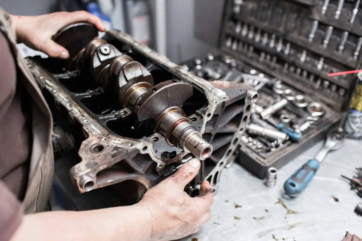
A fatigue fracture is a fracture phenomenon induced after a certain number of cyclic loads or alternating stress on the metal part. In mechanical part failure, fatigue fractures account for a large proportion, around 50% to 80%.
Shafts, gears, internal combustion engine connecting rods, and others are subjected to alternating loads, and most of their fractures are fatigue fractures.
The macroscopic features of fatigue fracture surfaces can be clearly divided into three regions: the fatigue origin area, fatigue crack propagation area, and instantaneous fracture area. The fatigue origin area is where the fatigue crack initially forms, usually occurring on the surface of the part.
However, if the material surface is hardened or there are internal defects, it can also occur just below the surface or inside the part. The fatigue origin area is often a small region with a smooth and clean surface where beach marks are not evident.
The most noticeable feature of the fatigue crack propagation area is the macroscopic fatigue striations and microscopic fatigue lines. Fatigue striations roughly form concentric circles or arcs around the fatigue origin, expanding outward like ripples in water, perpendicular to the crack propagation direction.
The instantaneous fracture area is the rapid fracture region that occurs when the fatigue crack expands to a critical size. Its macroscopic feature is similar to the rapid fracture region and shear lips in the static load tensile fracture.
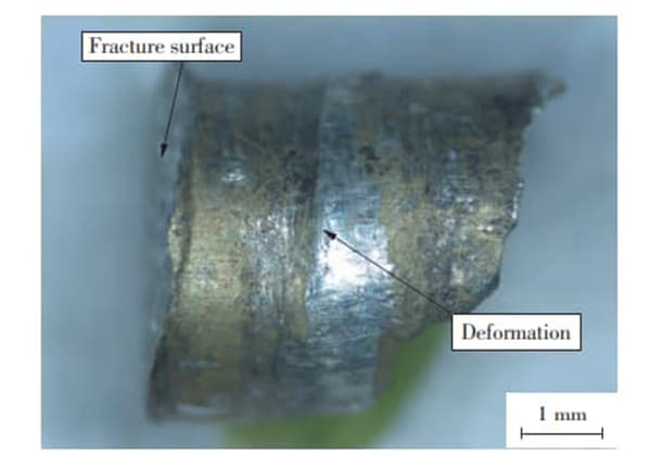
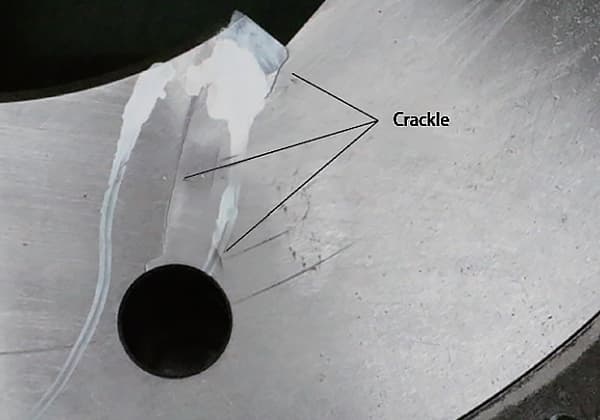
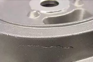
The macroscopic appearances of various types of fracture surfaces are shown in Figures 1-4. Through the study of the fracture surfaces of broken parts, the nature and type of fracture can be inferred, and the cause of damage can be found, so preventive measures can be taken.
2) Analysis of Fracture Failure and Its Countermeasures
①Fracture Failure Analysis – The steps are as follows:
a. Field Investigation
After a fracture occurs, it’s important to promptly investigate and record the circumstances before and after the fracture, including taking photos or videos if necessary. The fragments from the broken part must be carefully preserved to prevent oxidation, corrosion, and contamination.
They should not be moved or cleaned until the fracture characteristics have been identified and photographed. The working conditions, operational situation, and surrounding environment at the time should also be thoroughly investigated and recorded.
b. Analysis of the Primary Failure Component
When a key component fractures, this can often lead to other associated components breaking. In such instances, it’s crucial to establish a clear order of events and accurately identify the primary fracture component, as failure to do so could mislead the analysis results.
The primary failure component may be shattered, and its fragments should be collected and reassembled to identify the first crack, which is the principal crack.
c. Fracture Analysis
Start with a macroscopic analysis of the fracture, observing and analyzing the fracture with the naked eye or a low-power magnifying glass of 20x or less. Prior to the analysis, clean any oil stains from the damaged part.
Rust on the fracture can be removed chemically or electrochemically to remove the oxide layer. Carefully observe the fracture’s morphology, the location of the crack, and the relation between the fracture and deformation direction to determine the relationship between the crack and the forces involved and the location of the crack origin.
Identify the cause and nature of the fracture to provide a basis for microscopic analysis.
Then, conduct a microscopic analysis of the fracture using a metallographic microscope or an electron microscope to further analyze the relationship between the fracture morphology and microstructure; changes in the microscopic regions during the fracture process; the nature, shape, distribution of the fracture’s metallographic structure and inclusions; along with the microhardness and origin of the crack.
d. Inspection
Perform an inspection of the metallographic structure, chemical composition, and mechanical properties to study if there are any macroscopic or microscopic defects in the material, the distribution and development of cracks, and whether the metallographic structure is normal. Verify if the metal’s chemical composition meets the requirements and whether its regular mechanical properties are satisfactory.
e. Determine the Cause of Failure
When determining the cause of a part’s failure, consider factors such as the material of the part, manufacturing process, load condition, assembly quality, years in use, the medium and temperature in the working environment, and the usage condition of similar parts. Combine these with the macroscopic and microscopic characteristics of the fracture to make an accurate judgment and identify the primary and secondary causes of the fracture failure.
②Determine the Countermeasures
After identifying the cause of the fracture failure, consider countermeasures from the following perspectives:
a. Design
During part structural design, try to minimize stress concentration and choose materials reasonably according to the environmental medium, temperature, and nature of the load.
b. Process
Surface strengthening treatments can significantly enhance the fatigue life of parts, and appropriate surface coatings can prevent brittle fractures caused by impurities. During heat treatment of certain materials, introducing a protective gas into the furnace can greatly improve their properties.
c. Installation and Use
First, ensure correct installation to prevent additional stress and vibration, and prevent important parts from getting bumped or scratched. Second, pay attention to proper use, protect the operating environment of the equipment, prevent corrosion from corrosive media, prevent excessive temperature differences in different parts of the item. For instance, some equipment needs to idle at low speed for a while during winter production, and only after all parts have preheated can it operate under load.
(5) Deformation of Components
1) Basic Concept of Component Deformation
During the operation of mechanical equipment, deformation refers to changes in the size or shape of a component due to applied forces. Excessive deformation is a key type of mechanical failure and a clear sign of ductile fracture.
Some mechanical components, because of deformation, may cause additional loads on assembled parts, accelerate wear, affect the interrelationships among various components, or even lead to catastrophic outcomes such as fractures.
For instance, deformation such as the bending of various drive shafts, deflection or twisting of the main beam of a bridge crane, torsional deformation of a car’s main beam, or deformation of basic components like cylinder blocks or gearbox casings, can compromise positional accuracy among them. If the amount of deformation exceeds permissible limits, the component will lose its designated function.
2) Types of Part Deformation
① Elastic Deformation of Metals
Elastic deformation refers to the portion of a metal’s deformation that can fully recover after the removal of external forces.
The mechanism of elastic deformation is that atoms in the crystal deviate from their original equilibrium positions under external forces, causing changes in the distance between atoms and thus leading to stretching or twisting of the crystal lattice.
Therefore, the amount of elastic deformation is very small, generally not exceeding 0.10% to 1.0% of the original length of the material. Moreover, metals comply with Hooke’s law within the range of elastic deformation, i.e., stress is directly proportional to strain.
Many metal materials will undergo delayed elastic deformation under stresses below the elastic limit. Under a certain magnitude of stress, the specimen will produce a certain equilibrium strain.
However, this equilibrium strain does not occur instantly under stress, but requires a sufficiently long period of stress to fully develop. After the stress is removed, the equilibrium deformation does not instantly disappear; it requires a sufficient amount of time to fully disappear.
The phenomenon wherein the equilibrium strain lags behind the stress when the material undergoes elastic deformation is known as the elasticity lag phenomenon, also referred to as the elastic aftereffect.
Parts such as crankshafts that have undergone cold straightening will bend again after a period of time, a phenomenon caused by the elastic aftereffect. The way to eliminate the elastic aftereffect is through long-time annealing, with the annealing temperature of standard steel parts at 300 to 450°C.
If a metal part undergoes excessive elastic deformation beyond the design allowance during its use, it will affect the normal operation of the part. For example, during the operation of a drive shaft, excessive elastic deformation can lead to a deterioration of gear meshing on the shaft, affecting the working life of the gear and the roller bearing supporting it.
Excessive elastic deformation of a machine tool guide or spindle will cause a decrease in machining accuracy or even fail to meet machining accuracy requirements. Therefore, it’s crucial to prevent excessive elastic deformation in the operation of mechanical equipment.
② Plastic Deformation of Metals
Plastic deformation refers to the permanent deformation of a metal that can’t be recovered after the removal of external forces.
Most metals in actual use are polycrystalline, and most are alloys. Due to the existence of grain boundaries in polycrystals, the different orientations of each grain and the presence of solute atoms and different phases in alloys, not only do they hinder and restrict the deformation of each grain, but they also severely hinder the movement of dislocations.
Therefore, the deformation resistance of polycrystals is higher than that of single crystals, making deformation more complex. From this, it can be seen that the finer the grain, the more grain boundaries there are per unit volume, thereby resistance to plastic deformation is greater, meaning higher strength.
Plastic deformation of metal materials will cause changes in their organizational structure and properties. Large plastic deformation will destroy the isotropy of polycrystals, exhibiting anisotropy; it will also cause work hardening in metals.
At the same time, due to the differences in grain orientations and the blocking effect of grain boundaries, the deformation of each grain and within each grain during plastic deformation of polycrystals is uneven.
Therefore, after the external force is removed, the elastic recovery of each grain is different, which leads to the generation of internal stress or residual stress in the metal. Additionally, plastic deformation increases the reactivity of atoms, causing a decrease in the corrosion resistance of the metal.
Plastic deformation leads to changes in the dimensions and shapes of various parts of mechanical components, which will result in a series of adverse consequences. For example, plastic bending of a machine tool spindle will not guarantee machining accuracy, leading to an increase in the reject rate, and may even render the spindle inoperable.
Although local plastic deformation of a part does not cause failure as obviously as overall plastic deformation, it is also an important cause of part failure. Key connections, spline connections, stops, and pins, due to the effect of static pressure, usually cause local plastic deformation on the contact surface of one or both mating parts.
As the amount of extrusion deformation increases, especially for those parts that can move in reverse, it can lead to impacts, intensifying the process of breaking the original mating relationship, which in turn leads to mechanical part failure.
3) Reasons for Part Deformation
The main causes of part deformation are as follows:
1) Working Stress
When the working stress, caused by external loads, exceeds the yield limit of the part material, permanent deformation of the part will occur.
2) Working Temperature
As temperature increases, atomic thermal vibrations in the metal material intensify, the critical shear resistance decreases, and slip deformation occurs more easily, reducing the yield limit of the material. Or, if the part is unevenly heated with significant temperature differences, large thermal stresses can cause deformation.
3) Residual Internal Stress
Parts undergo residual internal stress during both the rough manufacturing and machining processes, impacting their static strength and dimensional stability. This not only lowers the elastic limit of the part but also leads to plastic deformation that reduces internal stress.
4) Internal Material Defects
Internal impurities, hard spots, and uneven stress distribution in the material can cause part deformation during use. It’s worth noting that part deformation doesn’t necessarily occur all at once under the influence of a single factor. Rather, it’s usually the cumulative result of several factors acting together.
Therefore, to prevent part deformation, measures must be taken from design, manufacturing process, usage, maintenance, and repair to avoid and eliminate the above factors, thereby keeping part deformation within acceptable limits.
In use, part deformation is inevitable. Therefore, during major equipment overhauls, it’s not sufficient to only check the wear of mating surfaces. The positional accuracy must also be carefully inspected and repaired, especially for machinery undergoing its first major overhaul.
Attention must be given to the inspection and repair of deformation, because deformation of parts under the influence of internal stress usually completes within 12 to 20 months.
4) Strategies to Prevent and Reduce Deformation of Mechanical Parts
In actual production, the deformation of mechanical parts is inevitable. The causes of deformation are multifaceted, thus measures to mitigate deformation should consider aspects such as design, processing, repair, and use.
i) Design
When designing, not only the strength of the parts should be considered, but attention should also be given to the rigidity of the parts along with issues related to manufacturing, assembly, usage, disassembly, and repair.
a. Choose the appropriate material, taking into account its process performance such as the fluidity and shrinkage of casting; the forgeability and cold-heading property of forging; the cold crack and hot crack tendency of welding; the machinability of machining; the hardenability and brittleness of heat treatment, etc.
b. Select the appropriate structure, arrange components logically, and improve the stress conditions of the parts. For example, avoid sharp corners, edges, replace them with rounded corners, chamfers, drill process holes or thicken parts in areas with significant thickness differences; arrange the position of holes well, change blind holes to through holes; for complex-shaped parts, consider using a combined structure, inlaid structure, etc.
c. In the design, attention should also be paid to the application of new technologies, new processes, and new materials, to reduce the internal stress and deformation during manufacturing.
ii) Processing
A series of process measures should be taken during processing to prevent and reduce deformation.
a. Aging treatment should be applied to the raw material to eliminate its residual stress.
b. When formulating the processing procedure for mechanical parts, measures to reduce deformation should be adopted in the arrangement of operations and steps, as well as in the process equipment and operations. For example, following the principle of separating rough and fine processing, leave a storage time in between to facilitate the elimination of internal stress.
c. The conversion of references should be minimized during the processing and repair of mechanical parts, try to retain the process reference for repair use, reduce errors caused by non-uniform references during repair processing.
For parts that have undergone heat treatment, it is necessary to pay attention to reserving machining allowance, adjusting machining dimensions, and pre-deforming.
After understanding the deformation pattern of the parts, reverse deformation can be added in advance, which can be counteracted after heat treatment; stress can also be pre-added or the generation and change of stress can be controlled, so that the final deformation meets the requirements and the purpose of reducing deformation is achieved.
iii) Repair
a. In order to minimize the stress and deformation caused during repair, it is not enough to just check the wear condition of the matching surface during major mechanical repairs, the positional accuracy of each other must also be carefully inspected and repaired.
b. Reasonable repair standards should be established, and simple, reliable, and easy-to-operate special tools, inspection tools, and measuring tools should be designed. At the same time, the promotion of new repair technologies and processes should be emphasized.
iv) Usage
a. Strengthen equipment management, strictly enforce safety operation procedures, intensify inspection and maintenance of mechanical equipment to prevent overloading and localized overheating.
b. It’s also important to correctly install equipment. Precision machine tools should not be used for rough machining. Store spare parts and accessories appropriately.
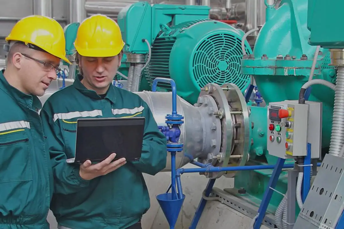
Influence of various factors during use
Mechanical equipment gradually deteriorates or ages due to various factors during use, leading to malfunctions or even loss of intended functionality. The main external factors include the following:
- Effect of abrasive particles
Most mechanical equipment is affected by dust and abrasive particles in the surrounding environment. If the equipment directly contacts these particles or lacks any protective measures, the lifespan of the mechanical equipment can vary extensively.
- Corrosive effects
Corrosion refers to the damage inflicted on the metal surface due to chemical and electrochemical reactions with the surrounding medium. Corrosion and wear often coexist. The corrosion process involves friction, which alters the quality and brittleness of the material. The friction causes the corrosion layer to quickly peel off. This combined effect of corrosion and wear is called corrosive wear or fretting corrosion.
- Natural factors
Natural climatic conditions, in addition to humidity, such as temperature, atmospheric pressure, and solar radiation, can potentially cause various damages to electrical equipment, plastics, and rubber products.
- Load conditions
The impact of load conditions on mechanical status varies. Different magnitudes of loads cause different degrees of wear. When the load exceeds the design average load, the wear process of the parts is accelerated, which could even lead to accidents. Conversely, reducing the load will decrease wear. Studies and practices have also shown that intermittent loads significantly impact the wear of parts.