Have you ever wondered how modern welding achieves such precision and efficiency? Arc welding inverters might hold the key. These devices transform electrical energy to create powerful welding arcs, adapting dynamically to complex welding conditions. In this article, you’ll discover how these inverters work, their main components, and the principles behind their operation. By the end, you’ll understand how arc welding inverters enhance welding performance, making them indispensable in various industrial applications. Dive in to explore the technological marvels that make precision welding possible.
The transformation between direct current (DC) and alternating current (AC) is called inversion. The device that accomplishes this transformation is called an inverter. An inverter that provides electrical energy for welding arcs and has the required electrical performance for arc welding processes is called an arc welding inverter.
The special nature of arc welding inverter:
The power supply object for welding is a special arc load, especially for arc welding with short-circuit transition, which requires the inverter to withstand the intense dynamic load that is constantly changing. The working conditions are very complex.
Main Components and Their Functions of Arc Welding Inverters
The main components include the power supply system, electronic power system, electronic control system, feedback circuit, given circuit, and welding arc.
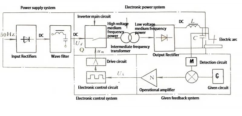
Figure 1: Block diagram of the main components and basic principles of arc welding inverters
From the diagram, it can be seen that the main components and their functions of the arc welding inverter are as follows:
Inverter main circuit: Consisting of the power supply system, electronic power system, and welding arc, it is responsible for the transmission and conversion of electrical energy.
Electronic control system: Provides sufficient switch pulse signals to the electronic power system (inverter main circuit) according to the variation law required by the arc, driving the operation of the inverter main circuit.
Feedback and given system: It consists of detection circuit (M), given circuit (G), comparison and amplification circuit (N), etc. Together with the electronic control system, it realizes the closed-loop control of the arc welding inverter, and enables it to obtain the required external and dynamic characteristics.
Basic Principles of Arc Welding Inverters
The basic principle of arc welding inverters can be summarized in the block diagram shown in Figure 1.
In the power supply system, single-phase (or three-phase) 50Hz or 60Hz AC network voltage of 220V (or three-phase 380V) is rectified and filtered by the input rectifier (UR1) and filter (LC1), obtaining a smooth DC voltage of about 310V (or about 520V for three-phase rectification), which is required by the inverter main circuit.
The DC voltage is then converted into high-frequency AC voltage ranging from several kilohertz to two hundred kilohertz by the alternating switching action of the high-power switching electronic devices (such as thyristors, transistors, field effect transistors or IGBT) in the inverter main circuit Q of the electronic power system.
After that, the voltage is stepped down to tens of volts suitable for welding through the high (medium) frequency transformer (T), and then the external and dynamic characteristics required by the arc welding process are obtained through the control driving circuit and the feedback and given circuit (M, G, N, etc.) of the electronic control system, as well as the impedance of the welding circuit.
If direct current is required for welding, the high (medium) frequency AC is converted into DC output by the output rectifier U and the filter of the inductance L2 and capacitor C2.
The rectification process of arc welding inverters can be simply described as follows: AC input → rectification to DC → high/medium frequency AC conversion → voltage reduction → AC output → rectification to DC again.
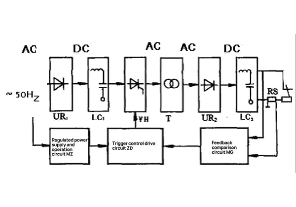
There are three types of inverter structures that can be used in arc welding inverters:
AC-DC-AC
AC-DC-AC-DC
AC-DC-AC-DC-AC (square wave AC).
Electrical Output Characteristics of Arc Welding Inverters
In order to meet the requirements of arc welding process, the electrical output characteristics (performance) of arc welding inverters must have corresponding adaptability. The electrical output characteristics mainly include external characteristics, regulation performance, and dynamic characteristics.
1. External Characteristics of Arc Welding Inverters
Arc welding inverters use electronic control systems and current-voltage feedback to perform closed-loop control of the electronic power system (inverter), in order to obtain different external characteristic curve shapes.
Based on the basic principle block diagram of the arc welding inverter (Figure 1), the closed-loop control system of the arc welding inverter can be described using block diagrams and equations, as shown in Figure 2.
Figure 2: Schematic diagram of the closed-loop control system of the arc welding inverter
The balance relationship of the closed-loop control system is established as follows: The arc voltage (Uf) is negatively fed back in the diagram, and the output voltage is sampled (usually by a voltage divider) to obtain a feedback quantity (mUf) proportional to it. The arc current (If) is also negatively fed back, and the output current is sampled (usually by a shunt or Hall element) to obtain a feedback quantity (nIf) proportional to it. The feedback quantities mUf and nIf are then compared and amplified with the arc voltage set value (Ugu) and the arc current set value (Ugi) respectively, resulting in K1(Ugu-mUf) and K2(Ugi-n) outputs. Finally, the control voltage (Uk) is obtained through synthesis and amplification, and then input to the control drive circuit to drive the electronic power system (inverter) operation.
Figure 3: External characteristics of the arc welding inverter.
Obtaining the constant voltage, constant current, and soft dropping characteristics:
1 – Constant voltage characteristic 2 – Constant current characteristic 3 – Soft dropping characteristic 4 – Constant current with external dragging characteristic
2. Regulatory Performance of the Arc Welding Inverter
Figure 4: Schematic diagram of standard regulation for arc welding inverters a) Constant voltage characteristic b) Constant current characteristic
From the principle of the external characteristic curve of the arc welding inverter, it can be inferred that for a given voltage value of the constant voltage characteristic, the size of the output arc voltage is determined. In other words, if the given voltage is high, the arc voltage is also high, and vice versa. For example, if Ugu1 < Ugu2, the external characteristic curve moves from curve 1 to curve 2, as shown in Figure 4a, and the stable operating point moves from A1 to A2.
For the constant current characteristic, the size of the voltage value for a given current determines the size of the output welding current. In other words, if Ugi is large, the output welding current is also large, and vice versa. For example, if Ugi1 < Ugi2, the external characteristic curve moves from curve 1 to curve 2, as shown in Figure 6-4b, and the stable operating point moves from AI to A2.
Generally, different types of arc welding inverters adopt different regulation systems to achieve control of the external characteristics and adjustment of process parameters to meet the different requirements of the welding process. We will introduce the working principles of different types of arc welding inverters one by one.
3. Dynamic Characteristics of Arc Welding Inverters
When arc welding inverters are used for arc welding processes with short circuit transitions involving molten droplets, strict requirements must be placed on their dynamic characteristics. The main parameter that affects the short circuit transition of MAG/CO2 welding is the rate of rise of short circuit current (disd/dt), which is directly related to the time constant T (T=L’/Rf, where L’ is the equivalent inductance of the welding circuit, and Rf is the arc resistance). Rf varies with the welding current and cannot be arbitrarily changed, while L’ can be changed by adding inductors to the welding circuit. In addition, the disd/dt can be changed by adjusting the time constant of the closed-loop system.
There are generally two ways to improve and control the dynamic characteristics of arc welding inverters:
Adding inductors to the welding circuit. Inductors are usually added not only to improve the dynamic characteristics but also for filtering purposes.
Designing electronic inductor arc welding inverters, which use electronic circuits instead of iron-core inductors to control the disd/dt, thereby demonstrating their superior control performance.
4. External characteristics, adjustment characteristics, and the control mode of output pulses
Typically, arc welding inverters use three adjustment control modes to control external characteristics, adjustment characteristics (process parameter adjustment), and form output pulse waveforms:
Fixed pulse width frequency modulation: the pulse voltage width remains unchanged, and the external characteristic curve shape, adjustment characteristics (adjustment of process parameters), and output pulse waveform are formed by changing the inverter’s switching frequency.
Fixed frequency pulse width modulation: the pulse voltage frequency remains unchanged, and the external characteristic curve shape, adjustment characteristics (adjustment of process parameters), and output pulse waveform are formed by changing the duty cycle (pulse width ratio) of the inverter’s switching pulse.
Hybrid adjustment: a combination of fixed pulse width frequency modulation and fixed frequency pulse width modulation is used for adjustment.
Basic Form of the Main Circuit of an Arc Welding Inverter
Several commonly used basic forms of inverter main circuits are shown in Figure 6.
Figure 6 Commonly used basic forms of inverter main circuits
a) Single-end forward type b) Half-bridge type c) Full-bridge type d) Parallel type.
Single-end forward inverter main circuit:
As shown in Figure 6a, power switching transistors (represented by electronic switch symbols) V1 and V2 are periodically turned on and off at the intermediate frequency, thereby inverting the input DC voltage into intermittent intermediate frequency voltage. The voltage is then stepped down by the intermediate frequency transformer T, rectified by the fast diode VD1, filtered by the inductor, and output as DC voltage to the arc. The two switching transistors simultaneously bear the input voltage, requiring a relatively low voltage resistance, making it suitable for medium and small power inverters.
Half-bridge inverter main circuit:
As shown in Figure 6b, the input DC voltage is divided equally by two sets of electrolytic capacitors. The two power switching transistors V1 and V2 are switched on and off alternately to form a rectangular waveform AC voltage.
After being stepped down by T, the full-wave rectification by VD1 and VD2 produces DC output. VD1 and VD2 must be fast diodes capable of withstanding double the output voltage amplitude. V1 and V2 only bear 1Ud/2, and have relatively low voltage resistance requirements.
Full-bridge inverter main circuit:
As shown in Figure 6c, two pairs of power switching transistors V1, V4 and V2, V3 on opposite bridge arms are periodically switched on and off at intermediate frequency. The rest of the operation is the same as the half-bridge. Power switching transistors also only bear a certain voltage, making it suitable for medium to high power welding requirements.
Parallel inverter main circuit:
As shown in Figure 6d, this type of main circuit is also known as a push-pull inverter main circuit. Power switching transistors V1 and V2 are periodically switched on and off at intermediate frequency.
After being stepped down by T, VD1 and VD2 perform full-wave rectification to output DC voltage. Switching transistors bear more than twice the voltage, requiring high voltage resistance. Generally, it is only used in thyristor-type inverters.
Arc Welding Inverter Control and Drive Circuit
The electronic control system of an arc welding inverter actually includes both electronic control circuits and drive circuits. They are another important component for achieving the electrical performance of the arc welding inverter. Therefore, it is necessary to have a deep understanding of the functional requirements for these circuits and how to better fulfill these requirements.
1. Basic functional requirements for electronic control circuits
The role of electronic control circuits is to provide a pair of rectangular pulse trains (excluding thyristor inverters) with steep leading and trailing edges, a phase difference of 180°, symmetry, and variable width or phase shift to the drive circuit of the arc welding inverter.
For some inverters, such as half-bridge and full-bridge inverters, the pulse trains must be isolated from each other. For a single-ended inverter, only one set of pulses is needed.
The design goal is achieved through the relationship between the presence or absence of paired pulse voltages, narrow and wide pulses, the amount of change in pulse width, or changing pulse frequency or phase, as well as the relationship between the basic pulse width, the minimum pulse width, and the speed at which the pulse width increases from the minimum to the rated width, and the relationship between the minimum and rated pulse frequency.
More specifically, the control circuit must have the following basic functions:
The drive circuit provides a pulse train with steep leading and trailing edges, a phase difference of 180°, and symmetry. Depending on the type of inverter and the adjustment system, the pulse width may be variable or the frequency may be adjustable.
The circuit must have sufficient gain to allow the output voltage and current of the arc welding inverter to reach the specified accuracy within the allowable range of input grid voltage and load current changes.
Obtain the specified output voltage and current regulation range.
Implement soft start for input and output voltage.
It should be able to output the electrical performance (external characteristics, adjustment characteristics, dynamic characteristics, and waveform) required by the arc welding process.
When the load power (including arc voltage and current) exceeds the rated value, the output power should be automatically limited or the main circuit power supply should be cut off.
Control circuit should be able to achieve electrical isolation and insulation between output and feedback input in general cases.
Turn on and off the main circuit power supply and control circuit power supply in the designed sequence.
In robot welding, semi-automatic and automatic welding, the operator should operate the inverter through a remote control box while keeping a safe distance from the arc welding inverter.
There should be strong and weak electrical interfaces that are connected to peripheral devices.
Other functions:
For bridge or push-pull inverter main circuits, the control circuit must have the ability to automatically balance when there is asymmetry in two half cycles.
Temperature monitoring (temperature monitoring of key components such as high-power switching tubes and high-frequency transformers).
Warning and indication of current limiting, overload, and phase loss states should also be considered when necessary.
2. Basic functional requirements for drive circuits
The pulse control signals provided by the control circuit must have sufficient power. However, due to the different types, models, and capacities of switching tubes, the power requirements for the drive pulse signals also differ.
Different types of inverter main circuits also have different isolation requirements for the drive pulse signals.
For example, in full-bridge and half-bridge inverter main circuits, the switching tubes located at high and low potentials require reliable isolation of the drive pulse signals.
The drive circuits for thyristor-based and transistor-based inverters have different characteristics and requirements.
Requirements for the drive circuit of thyristor-based inverters:
The triggering pulse signal should have sufficient power (voltage and current).
The triggering pulse signal should have sufficient width to ensure reliable conduction of the thyristor.
The triggering pulse waveform should facilitate thyristor conduction. In a parallel circuit of high current thyristors, the parallel components are required to conduct simultaneously, allowing the switching tube to operate within the allowable range.
It must be ensured that the thyristor can be reliably turned off when necessary.
Requirements for the drive circuit of transistor-based inverters:
The role of the drive circuit for transistor-based inverters is to amplify the pulse output of the control circuit to a level sufficient to excite high-voltage switching tubes. The amplitude and waveform of the drive pulse provided are related to the operating characteristics of the transistor, such as saturation voltage drop, storage time, voltage and current rise and fall rate of the collector or emitter at the moment of opening and closing, which directly affect its loss and heat generation.
The drive circuit is one of the main factors determining the performance of PWM inverters.
Characteristics, Classification, and Applications of Arc Welding Inverters
Characteristics of Arc Welding Inverters:
Compared to traditional arc welding power sources which use a frequency of 50Hz or 60Hz to transmit energy and change electrical parameters, arc welding inverters increase the frequency to several thousand to two hundred thousand Hz for energy transmission and conversion.
This increase in frequency provides arc welding inverters with outstanding features in terms of structure and performance, including high efficiency and energy savings, lightweight and material-saving design, fast dynamic response, and excellent electrical and welding process performance.
Specifically, when compared to traditional arc welding power sources such as arc welding transformers, DC arc welding generators, silicon arc welding rectifiers, and thyristor arc welding rectifiers, arc welding inverters have the following significant characteristics and advantages:
High efficiency and energy savings: with an efficiency rate of 80% to 92%, arc welding inverters can save up to 20% to 35% of energy (varies with load size), and have minimal no-load power consumption, typically only a few tens to a few hundred watts, which is only a small fraction of traditional arc welding power sources.
Lightweight and compact design: the weight of the mid-frequency transformer is only a small fraction of that of the traditional arc welding power source, typically 1/10 to 1/3, and its volume is only 1/5 to 1/3, making it very convenient to move.
Excellent electrical performance.
Excellent welding process performance.
Classification of Arc Welding Inverters:
Arc welding inverters can be classified in different ways:
Based on different high-power switching devices used, common types include:
Due to its excellent electrical performance, good control performance, ability to obtain various shapes of output characteristics, different types of arc voltage and current waveforms (DC, pulse, rectangular wave AC), and excellent dynamic characteristics, arc welding inverters can output welding currents of up to 1000A or more.
Therefore, it can almost replace all existing arc welding power sources and be used for various arc welding methods such as manual metal arc welding, TIG welding, MAG/C02/MIG/flux-cored wire welding, plasma arc welding and cutting, submerged arc automatic welding, robot welding, and others.
It can weld various metal materials and alloys, especially in applications with limited workspace, high altitude operations, or where there is a shortage of electrical supply and a need for mobile welding machines.
As the founder of MachineMFG, I have dedicated over a decade of my career to the metalworking industry. My extensive experience has allowed me to become an expert in the fields of sheet metal fabrication, machining, mechanical engineering, and machine tools for metals. I am constantly thinking, reading, and writing about these subjects, constantly striving to stay at the forefront of my field. Let my knowledge and expertise be an asset to your business.
Imagine having the power to enhance your welding process with a device that's efficient, reliable, and versatile. Arc welding inverters are transforming the welding industry with advanced technologies like thyristors,…
Have you ever considered the unsung heroes holding our machines together? In this article, we'll explore the fascinating world of mechanical connections, from the humble rivet to the mighty weld.…
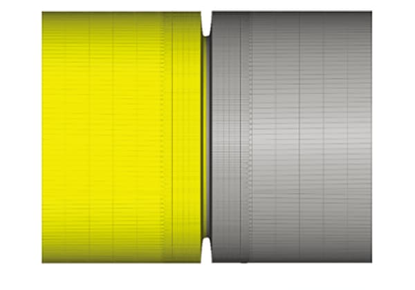
Abstract: The residual stress of butt joint of X80 pipeline steel was simulated by means of finite element analysis, and the distribution of residual stress was obtained. The prediction results…
Choosing between riveting and welding for your project can be tricky. Riveting involves mechanically joining parts with rivets, ideal for minimal deformation and harsh environments. Welding, on the other hand,…
Have you ever wondered why cracks appear in metal parts during manufacturing? In this insightful blog post, we'll dive into the intriguing world of forging cracks, heat treatment cracks, and…
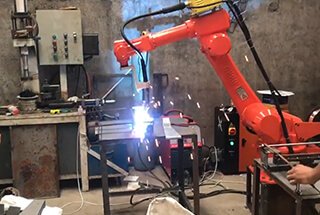
Ever wondered how robots are revolutionizing industries? From welding and cutting to assembling and sorting, industrial robots are transforming manufacturing processes with unmatched efficiency and precision. This article explores 13…
I. What Is Nondestructive Testing? Nondestructive testing is a general term that refers to all technical means used to detect defects or nonuniformity in an object being tested, by utilizing…
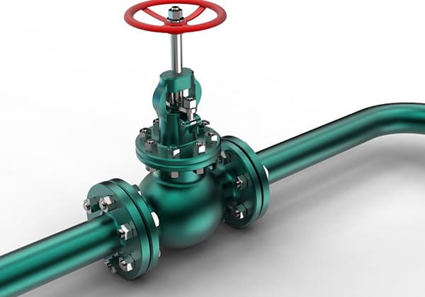
How do you choose between an orifice flowmeter and a wedge flowmeter? Both serve to measure flow, but they have distinct advantages and drawbacks. Orifice flowmeters are known for their…
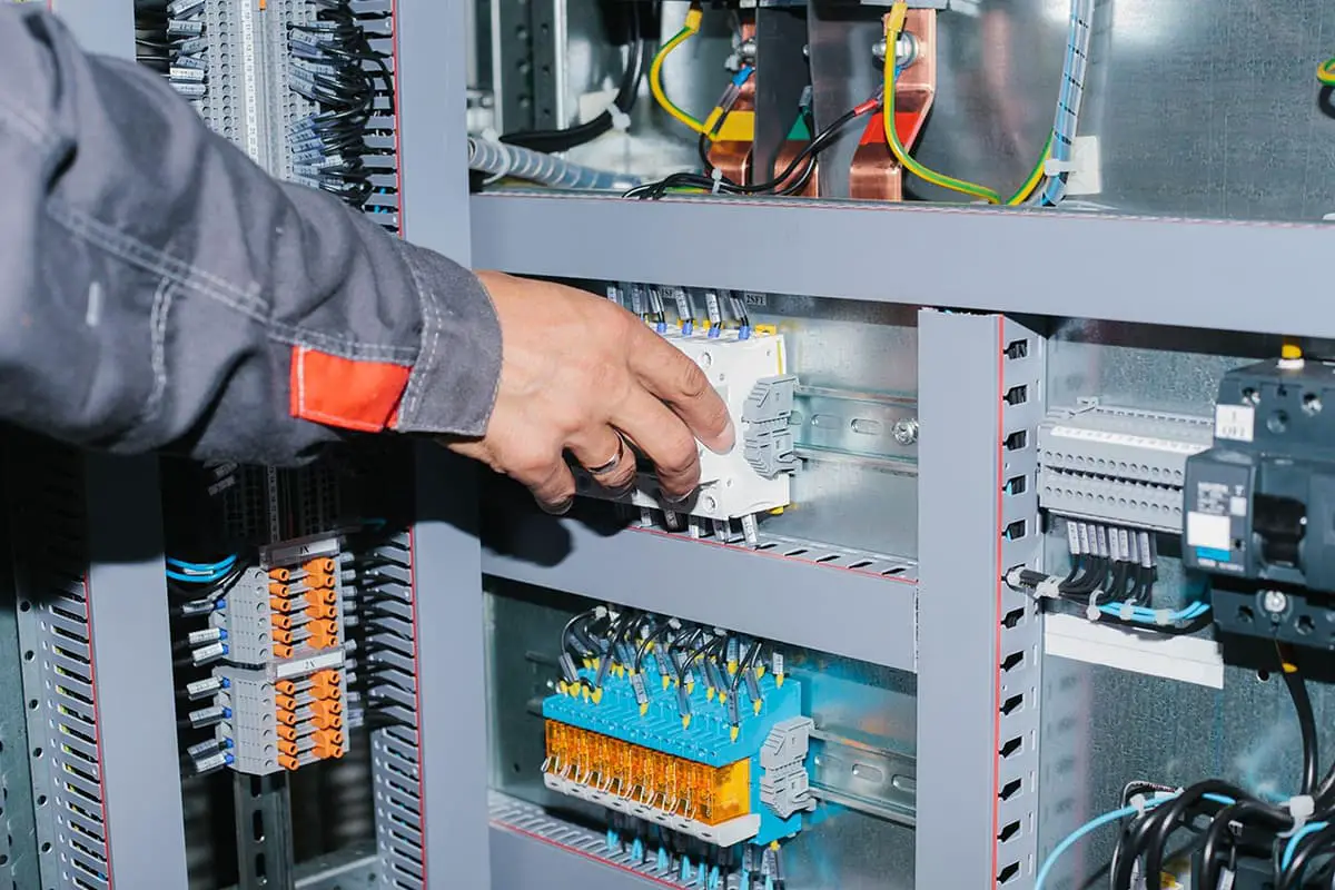
Ever wonder what it takes to ensure a flawless busbar installation? This comprehensive guide will walk you through each step, from technical preparations to the final adjustments, ensuring your project…