Laser Cutting Nozzle Selection: Cutting-Edge Tips
Have you ever struggled with choosing the right laser cutting nozzle for your project? Selecting the optimal nozzle is crucial for achieving clean, precise cuts and maximizing efficiency. In this…
Laser cutting revolutionized manufacturing, but even the most advanced machines encounter issues. In this blog post, we dive into common problems faced by laser plate cutting machines and provide step-by-step troubleshooting solutions. Our expert mechanical engineer breaks down each issue, from cutting inaccuracies to abnormal noises, offering clear explanations and practical fixes. Whether you’re an operator or maintenance professional, this guide will help you quickly diagnose and resolve laser cutting machine problems, ensuring optimal performance and minimizing downtime.
1.1. Cutting has sharp corners Solution steps
Solution steps (if the previous step is ineffective, proceed to the next step):
1.2. Cutting corrugation issue
Solution steps (if the previous step is ineffective, proceed to the next step):
1.3 Poor cutting accuracy
Solution steps (if the previous step is ineffective, proceed to the next one):
1.4 Abnormal noise issues
Solution steps (if the previous step is ineffective, proceed to the next one):
1.5 Diagonal discrepancy
Solution steps (if the previous step is ineffective, proceed to the next one):
1.6 X-axis, Y-axis, and Z-axis motion stalling
Solution steps (if the previous step is ineffective, proceed to the next one):
1.7 Cutting effect issues
Solution steps:
Structural steel: Cutting with O2
| Defects | Possible Causes | Solutions |
| No burrs, consistent lead-in lines | Appropriate powerSuitable cutting speed | |
| Significant bottom lead-in line offset, wider bottom kerf | Cutting speed too highCutting power too lowGas pressure too lowFocus too high | Decrease cutting speedIncrease cutting powerIncrease gas pressureLower the focus |
| Bottom burrs similar to slag, forming droplet shape and easy to remove | Cutting speed too highGas pressure too lowFocus too high | Decrease cutting speedIncrease gas pressureLower the focus |
| Connected metal burrs can be removed as a whole piece | Focus too high | Lower the focus |
| Metal burrs on the bottom surface are difficult to remove | Cutting speed too highGas pressure too lowImpure gasFocus too high | Decrease cutting speedIncrease gas pressureUse purer gasLower the focus |
| Burrs on one side only | Incorrect laser coaxial alignmentNozzle orifice defect | Adjust laser coaxial alignmentReplace nozzle |
Material ejected from the top | Power too lowCutting speed too high | Increase powerDecrease cutting speed |
| Cutting surface not precise | Gas pressure too highNozzle damagedNozzle diameter too largePoor material quality | Decrease gas pressureReplace nozzleInstall appropriate nozzleUse materials with smooth and even surfaces |
Stainless steel: Cutting with high-pressure N2
| Defects | Possible Causes | Solutions |
| Producing droplet-shaped small, regular burrs | Focus too lowCutting speed too high | Raise the focusDecrease cutting speed |
Long, irregular, filament-like burrs on both sides, and large plate surface discoloration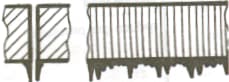 | Cutting speed too lowFocus too highGas pressure too lowMaterial too hot | Increase cutting speedLower the focusIncrease gas pressureCool down the material |
Long, irregular burrs on only one side of the cutting edge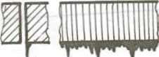 | Incorrect laser coaxial alignmentFocus too highGas pressure too lowSpeed too low | Adjust laser coaxial alignmentLower the focusIncrease gas pressureIncrease speed |
| Cutting edge turns yellow | Oxygen impurities in the nitrogen gas | Use high-quality nitrogen gas |
| Beam diverging at the starting point | Acceleration too highFocus too lowMelted material not ejected properly | Decrease accelerationRaise the focusPierce round holes |
| Rough kerf | Nozzle damagedLens dirty | Replace nozzleClean the lens, and replace if necessary |
Material ejected from the top | Power too lowCutting speed too highGas pressure too high | Increase powerDecrease cutting speedReduce gas pressure |
1.8 Component interference issue
Solution steps (proceed to the next step if the previous one is ineffective):
First, make a judgment, consult quality control inspectors, review drawings, if the component does not match the drawing, return it to the warehouse and replace it with a qualified component. If it matches the drawing, consult technical support personnel to verify the drawing and provide a specific solution. List of potential solutions:
1.9 Installation issues
Solution steps:
1.10 Interference issues
Solution steps:
1.11 Chiller alarm
Solution steps (proceed to the next step if the previous one is ineffective):
1.12 Z-axis limit alarm
Solution steps (proceed to the next step if the previous one is ineffective):
1.13 Driver alarm
Solution steps:
1.14 Tripping issue
Solution steps:
1.15 Cutting software error
1.16 Wiring error

2.1 Poor cutting accuracy with manual chuck
Solution steps (proceed to the next step if the previous one is ineffective):
2.2 Poor cutting accuracy with electric chuck
Solution steps (proceed to the next step if the previous one is ineffective):
2.3 Cutting start points do not coincide
Solution steps (proceed to the next step if the previous one is ineffective):
2.4 Cutting corrugation issue
Refer to Chapter 1 Tube Cutting Machine Problem 1.2.
2.5 Large edge-finding error
Solution steps (proceed to the next step if the previous one is ineffective):
2.6 Interference issue
Refer to Chapter 1 Sheet Cutting Machine Problem 1.10.
2.7 Water cooling machine alarm
Refer to Chapter 1 Sheet Cutting Machine Problem 1.11.
2.8 Z-axis limit alarm
Refer to Chapter 1 Sheet Cutting Machine Problem 1.12.
2.9 Driver alarm
Refer to Chapter 1 Sheet Cutting Machine Problem 1.13.
2.10 Tripping issue
Refer to Chapter 1 Sheet Cutting Machine Problem 1.14.
2.11 Cutting software error
Refer to Chapter 1 Sheet Cutting Machine Problem 1.15.
2.12 Wiring error
Refer to Chapter 1 Sheet Cutting Machine Problem 1.16.
With the evolution of the laser industry and changes in downstream industry demands, high-power laser cutting equipment has gradually become a focal point of market interest.
With unparalleled advantages in speed and thickness, high-power laser cutting has now garnered widespread market recognition.

However, as high-power laser cutting technology is still in its early stages of widespread adoption, some operators are not fully proficient in managing this cutting process, and often find themselves at a loss when faced with issues during production debugging.
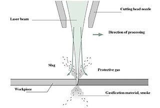
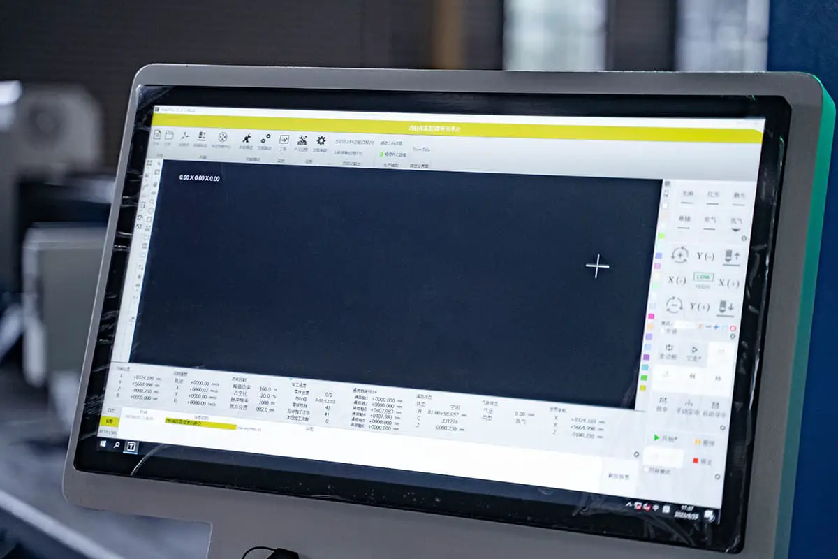
To address these problems in high-power cutting, cutting process technicians offer a few troubleshooting tips to help you adjust to the right laser cutting process parameters (Figure 1).
This will not only reduce the losses brought about by defective workpieces, but also enhance your cost-effectiveness from another perspective.
There are many reasons why high-power lasers can produce defective workpieces during the cutting process. The main issues can be diagnosed from the following four aspects.
If poor cutting results are detected, check for the following issues first:
1. Are the lenses contaminated?
2. Is the nozzle damaged?
3. Is the light centered on the nozzle?
4. Are there any leaks or damages in the ceramic body?
1. Possible reasons:
Incorrect nozzle selection—too big of a nozzle; incorrect air pressure setting—overburning with stripes due to too high pressure; incorrect cutting speed—overburning caused by too slow or too fast speed.
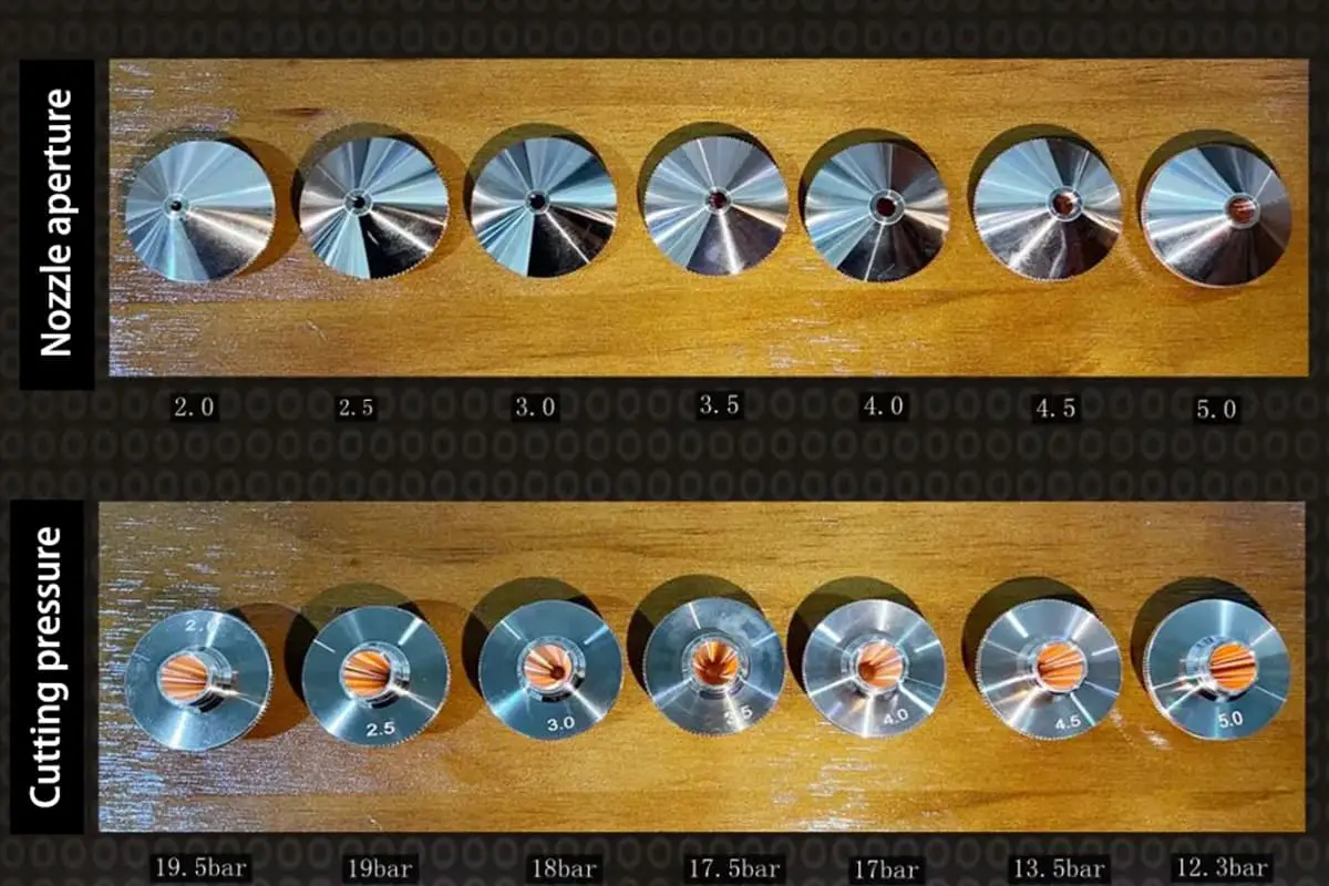
2. Solutions:
Change the nozzle, opt for a smaller diameter nozzle, for instance, a high-speed D1.4 nozzle for 16mm carbon steel bright cutting, and a high-speed D1.6 nozzle for 20mm carbon steel bright cutting; reduce the cutting air pressure to improve the cut section quality; adjust the cutting speed, so that the power matches the cutting speed to achieve the effect shown in Figure 2.

1. Possible Causes:
The nozzle used may be too small, cutting focus mismatched; air pressure too low or too high, cutting speed too fast; poor material quality of the plate, bad plate quality, small nozzles have difficulty removing slag.
2. Solutions:
Replace with a larger diameter nozzle, adjust the focus to the appropriate position; increase or decrease air pressure until the airflow is suitable; choose good quality plate material. This can achieve the effect shown in Figure 3.

1. Possible Causes:
The nozzle diameter is too small to meet the machining requirements; the negative defocus is mismatched and should be increased and adjusted to the appropriate position; the air pressure is too low, resulting in bottom burrs and insufficient cutting.
2. Solutions:
Use a larger diameter nozzle to increase the airflow; increase the negative defocus to enable the cutting section to reach the bottom position; increase the air pressure to reduce the bottom burrs. This can achieve the effect shown in Figure 4.

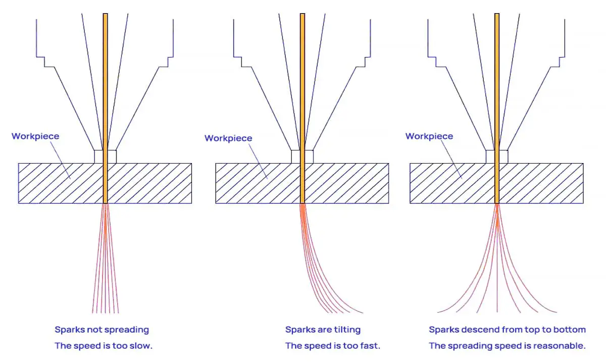
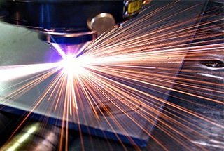
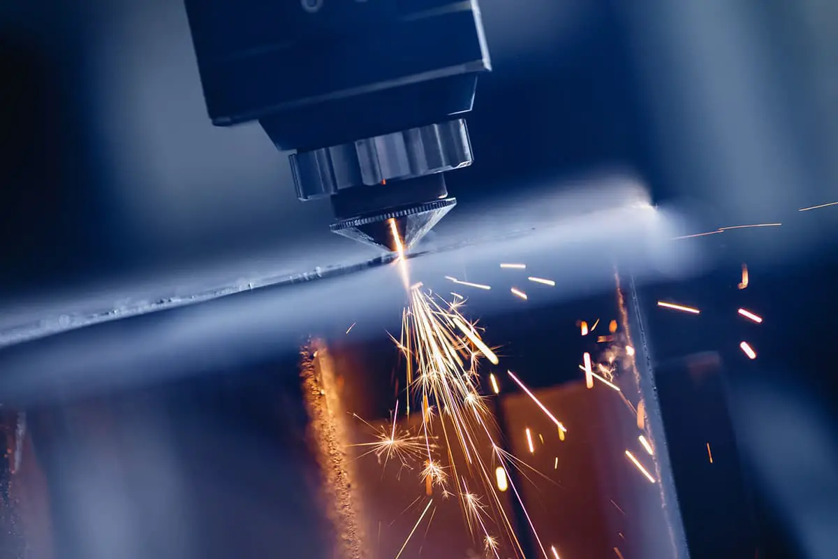
(1) Appropriate Cutting Speed: The cutting sparks diffuse downwards, resulting in a smooth cutting surface without residue at the bottom.
(2) Excessive Cutting Speed: The cutting sparks tilt.
(3) Insufficient Cutting Speed: The cutting sparks do not diffuse and are few, clustering together.
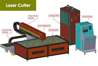
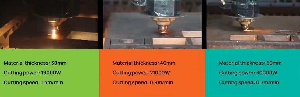
In response to these issues, the power of the laser cutting machine (see Figure 6) is compatible with the most widely used 20,000 to 30,000 watts in the current sheet metal processing market. With bilateral servo motors, it offers swift speeds, precise positioning, and smooth operation.

The high cutting speed is a significant advantage of laser cutting and the primary reason many sheet metal processing users choose laser cutters. However, faster isn’t always better. Only by controlling the appropriate cutting speed can a smooth, slag-free cut surface and high-quality workpieces be achieved.
The power of the laser impacts the speed at which the laser equipment cuts the sheet metal, and this cutting speed, in turn, affects the quality of the sheet metal cutting. Under fixed laser power, an optimum range of cutting speeds exists. Speeds that are either too fast or too slow can adversely affect the smoothness of the cut cross-section.
Laser cutting machines often encounter malfunctions during use. Without guidance from a professional, it can be difficult for us to accurately determine the source of the problem in the laser cutting equipment. We can only rely on our own experience to figure it out.
However, when some issues arise for the first time, we may feel at a loss and even struggle to describe the problem clearly when consulting the manufacturer’s after-sales support.
To help you out, I have carefully selected some common laser cutting machine issues and their corresponding sources or solutions.
1. Poor cutting quality or inability to cut through?
Potential causes include low power settings, small potentiometer adjustments, misaligned optics, dirty lenses, improperly installed focus lenses, focal length issues, laser power supply problems, laser tube power attenuation, high water temperature, and unstable voltage. Address these issues step by step based on the actual situation.
2. Unable to connect to the device?
Check if the board drivers are installed, if the USB or Ethernet cables are properly connected, if the cables are damaged, if the adapter board is faulty, and other issues related to the board.
3. Machine returns to the wrong origin when powered on?
The origin switch may be faulty.
4. Cutting shape deformation and overlapping cuts?
Possible causes include loose synchronous wheel screws, broken motor wires, a faulty motor, driver issues, and voltage problems.
5. Device won’t start, and the indoor circuit breaker trips when powered on?
Check if the emergency stop button is released, if the external circuit is connected, if the device’s internal circuit breaker is closed, and if you hear a “pop” sound when powering on. If so, inspect the main contactor and control transformer.
Additionally, check for water leakage in the water protection system causing a short circuit in the laser power supply (e.g., JGHY12570 water protection installed on the side with the laser power supply right below), a short circuit in the 107 water pump, or the use of an undersized indoor circuit breaker.
6. High-voltage wire arcing?
This issue can be quite troublesome. It is recommended to add a high-voltage insulating sleeve over the high-voltage wire.
7. Cutting graphic size too large or too small?
Check if the output graphic size is consistent, if there are changes in the Z-axis height position, and if calibration files need adjustments.
8. Different colors in the center and around the cut image?
Adjust the focusing coefficient and the W-axis focus point.
9. Damaged marks or coarser spots during marking?
Check the dynamics and DA board.
10. Marking graphic position offset?
Check for X or Y-axis displacement in the scanning mirror, find the center point, and adjust the XY-axis position according to the actual offset direction.
11. Scanning mirror’s XY-axis swings randomly when powered on, and the dynamic motor makes abnormal noises?
Replace the ±12±15V switch power supply; replace the ±12±28V switch power supply.
12. No laser output?
Check if the chiller’s return water flow is normal, if there are changes in the W-axis position, if the DC48V32A laser power supply is functioning properly, and other issues related to the laser tube.
13. No display on the control panel when powered on?
Check if the 5V12V24V switch power supply is functioning properly and inspect the display panel.
14. Control panel malfunctions and the machine doesn’t return to the origin when powered on?
Replace the offline control card.
15. Z-axis doesn’t feed material or moves weakly?
Potential causes include issues with the Z-axis feed motor, driver problems, bearings, or foreign objects causing obstruction.
16. Glass tube doesn’t emit light?
The output control of the glass tube mainly includes the laser tube, laser power supply, water circulation system, and output signal. The output signal consists of the PWM output signal from the control card, water protection signal, and door switch signal.
If the laser tube doesn’t emit light, focus on the laser tube, laser power supply, water circulation system, and output signal.
First, check if the laser power supply is functioning normally, if there are any abnormalities in the inner and outer tubes of the laser tube, and if the water circulation system is normal.
If not, replace or adjust accordingly. If everything is normal, consider the output signal.
First, test the laser tube and laser power supply using the short-circuit signal method. If this works, there are no issues with the laser tube or laser power supply, and the problem lies with the water protection switch, relay, door switch, or control card’s PWM signal.
If this method fails, the issue is with the laser tube or laser power supply, and you can use the replacement method to solve the problem.
17. RF laser tube doesn’t emit light?
Ensure the water circulation is clear and the laser power supply starts normally.
First, test if the 48V DC voltage from the laser power supply is normal. Check the conductivity of pins 4 and 13 on the laser tube’s 25-pin connector; conductivity indicates that the water protection signal is normal. If not, check the water protection.
Test the voltage between pins 7 and 20; a DC voltage of 4-5V when not pressing preset or start and 1-3V when pressing preset or start indicates a normal signal (low-level conduction).
If the water, power supply, and these two signals are normal, it’s generally a laser tube issue. If the signals are abnormal, it indicates a control card issue or a circuit problem.
18. RF laser tube replacement shows “laser tube connection error”?
If the connector (internal wires are not desoldered or short-circuited), power supply wires (left positive, right negative, and ground connected to the negative terminal), and water connections are normal, and the device still can’t connect properly after restarting the chiller and equipment, it’s generally an issue with the 25-pin connector’s connection circuit board or incompatibility, such as encrypted and non-encrypted tubes not being compatible with the circuit board.
19. Cutting machine misaligned cuts?
(Overcut or colinear graphics cut with a large distance)
1.) Feeding misaligned cuts:
2.) Non-feeding misaligned cuts:
20. Long feed on the feeding machine?
If the feeding machine feeds too long, it is usually due to a malfunctioning photoelectric switch or incorrect light sensitivity of the photoelectric switch. The light sensitivity of the photoelectric switch can be adjusted.
When both upper and lower switches are illuminated simultaneously while the feeding machine is working, the feeding machine will start.
If the light sensitivity is too high, the machine will sense light even when the cutting material is blocking it, leading to overfeeding. In this case, adjust the sensitivity knob on the photoelectric switch’s wiring until the indicator light is on when the material is blocking it.
21. Coarse light spot on the galvanometer machine?
If the light intensity is not sufficient and the basic optical path and beam expander optical path have been adjusted well, and the dynamic focal length has been adjusted well, but the light spot is still coarse, you need to adjust the distance between the two lenses of the beam expander.
For our commonly used 3x beam expander, adjusting the output beam spot diameter to 13-14 mm generally gives good results. You can also adjust it according to the customer’s processing requirements.
22. Galvanometer machine with dynamic self-excitation?
For Shanghai Dynamics, adjust R103 and R28 to regulate self-excitation and howling. If the adjustment is ineffective, measure if the motor shaft is short-circuited with the machine casing. During the measurement, disconnect the motor’s power supply wire; otherwise, it will be continuously conductive.
If it still conducts after disconnecting the motor’s power supply wire, use an insulating film to isolate the motor and the machine casing, then adjust R103 and R28 again. If it’s still ineffective after addressing these issues, replace the components.
23. Incorrect marking or cutting size on marking and cutting machines?
For dynamic marking machines, incorrect size without moving the galvanometer lens up and down is generally due to changed or erroneous calibration parameter data. Recalibrating the galvanometer parameters can solve the issue.
For cutting machines, incorrect cutting sizes are usually caused by errors in the step distance and driver pulse count. Generally, determining the pulse count and calculating the step distance can solve the issue.
24. Cutting machine reverses the home position direction when powered on?
This type of malfunction is usually caused by a damaged home position switch. There are two types of home position switches: proximity switches and reed switches (magnetic control switches). The reverse direction of the home position is generally caused by a short circuit in the switch coil. Replacing the switch can solve the issue.
25. Cutting machine motor, motor driver, motor wire, and driver DC power supply switch fault?
The specific manifestations of such faults on the equipment are generally:
(1) The laser head does not move
(2) The laser head movement is abnormal, with pauses or jitter during operation In such cases, first observe and measure if the 48V or 42V DC switching power supply is working properly.
Insufficient or unstable supply voltage can cause these phenomena. If the switching power supply works normally, consider if the fault lies with the driver, motor, or motor wire.
To determine if the motor is faulty, first check if the motor itself rotates smoothly without power and with the motor wire disconnected from the driver. If the motor’s rotation is abnormal, it can be directly determined as a motor fault and replaced. If the motor runs normally, measure the motor coil.
For a six-wire motor, AC, A+, and A- form one coil group; AC and A+ and A- should be conductive. BC, B+, and B- form another coil group, with the same conductivity situation. If the conductivity is abnormal, it can be directly determined as a motor fault.
For Baishan and YAKO stepper drivers, if the DC power supply is normal and the motor wire is disconnected, and the driver’s indicator light is off, it can be directly determined as a driver fault. If you cannot directly determine the fault, you can use the replacement method for testing.
Motor wire faults are low probability issues in this type of failure. If both the motor and driver have been ruled out, the motor wire should be considered. Check for short circuits and open circuits, and use a multimeter for detailed continuity testing to troubleshoot.
26. Laser tube does not emit light?
27. Laser tube emits weak light?
28. Can’t cut through?
29. Can’t start the machine?
30. 24V switch power supply is broken; machine X, Y-axis cannot move?
31. Machine X-axis or Y-axis does not move or is not powered?
32. Machine cutting misalignment
33. Cannot detect control card when connected to the machine?
34. Camera cutting is inaccurate
35. No light emission?
Short-circuit L and GND; if there is continuous light, it indicates that the laser power supply and laser tube have no issues, only signal issues. Short-circuit P and GND to determine if the water protection switch is normal. Short-circuit AIN and 5V; if there is continuous light, it indicates that the laser tube, laser power supply, and water protection are properly connected.
36. Computer and equipment cannot connect?
Update D13 driver; it could also be a USB cable issue.
37. When one axis can be pushed by hand during startup?
If the axis does not move during processing, it is generally a damaged driver; it could also be due to mechanical looseness in the transmission (e.g., if both axes do not move during processing and can be pushed by hand during startup, and the driver light is not on, it indicates that the 42V power supply is damaged).
38. Misalignment in one direction during cutting?
Increase driver current; it could also be a damaged driver or a motor wire issue.
39. Cutting has sawtooth pattern?
Slider issue.
40. Can’t cut through?
Laser tube may be weakened; beam path may be misaligned; it could also be the laser power supply.
41. Laser head hits the machine and cannot be limited?
The origin switch may be damaged, or it may not be set on the control panel.
42. Cutting doesn’t seal?
Adjust the belt and parameter settings.
43. Connected cutting machine has light during pre-adjustment but not during processing?
This is generally a control card issue.
44. Cutting dimensions are inconsistent?
Axis distance and pulse settings are not properly adjusted.
45. During work, a small section of a complete curve is skipped and not cut, also known as “skipping light”?
This issue is generally caused by the loosening of the large carriage slider during long-term high-speed operation. Simply readjust the sliders on both sides of the large carriage to resolve the problem.
46. During work, some areas on the same plate do not cut through while others do?
This issue is generally caused by beam misalignment or an uneven worktable. Adjust the beam path and level the worktable. Sometimes, beam misalignment is caused by rail deformation, in which case the rail needs to be adjusted.
47. During cutting, the ends sometimes cut into each other and sometimes separate?
This issue is generally due to loosening of the synchronous wheel fixing screws or problems with the motor wires. If there are issues with the motor wires, it is best to replace the entire group, not just one or two individual wires.
48. In summer, chiller is prone to high-temperature alarms?
This issue is generally caused by hot weather, poor heat dissipation in the chiller, or insufficient cooling capacity. DIY chillers do not typically have insufficient cooling capacity, and the problem is usually caused by dirty heat sinks or poor ventilation, resulting in alarms.
Small chillers may have insufficient cooling capacity; adjusting the temperature difference and increasing the alarm temperature can help resolve the issue.
49. Sometimes emits light and sometimes doesn’t?
First, check for unstable signals, including light emission signals and chiller signals. Then, check for any poor contacts in the potentiometer. Finally, inspect the power supply for any damage.
50. Upon startup, the machine doesn’t return to the origin, and can’t move.
This issue is generally due to the small carriage motor not being powered on. Under startup conditions, the laser head can be easily pushed by hand. The cause of the fault is usually a damaged 48V power supply or self-protection. Turn off the machine for ten minutes and turn it on again; if the problem persists, replace the 48V power supply.
51. The light from the laser tube becomes weak after cutting for a few minutes?
This issue generally has three possible causes: a problem with the power supply, a damaged laser tube, or an incorrect light emission frequency for the laser tube in the software.
52. Large carriage experiences violent shaking while moving?
This issue is usually caused by problems with the servo limit wires or limit switches. Replacing the wires or limit switches should resolve the issue.
53. Two laser heads move erratically?
This is generally due to a damaged control board, which produces incorrect signals.
54. Sometimes two patterns are required to be connected, but they don’t align when cut?
This issue is caused by the feeding drive axis and the small carriage aluminum profile not being parallel. The small carriage cannot be adjusted; the feeding drive axis must be adjusted to solve the problem.
55. Cutting has a sawtooth pattern?
Slider is loose or damaged, belt is loose, belt synchronous wheel is eccentric, curvature value is too high, corner speed is fast, lens is not tightened, etc.
56. Laser tube power is unstable; engraving is good at the beginning but varies in depth after a few days?
The laser tube and power supply are unstable.
57. No light emission?
Water level switch is leaking.
58. Laser power supply is arcing?
Welding area not properly connected, no silicone applied, high voltage wire touching metal.
59. Unable to cut through?
Beam misalignment, dirty or loose lens, incorrect focal length, laser tube power attenuation.
60. Machine won’t start?
Emergency stop, external power supply, contactor.
61. XY axis not moving?
Damaged driver, motor wire or connector issues, loose belt synchronous wheel, damaged 42V power supply.
62. Display panel not lighting up?
24V power supply is damaged, or the connection cable between the control board and display panel is damaged.
63. Poor cutting effect?
Yellow light around the cutting area is not correct, insufficient air blow.
64. Corner burning or dross occur while cutting right-angle parts?
When using a laser cutting machine to cut right-angle parts made of carbon steel or stainless steel, issues like corner burning or dross may arise due to various factors like cutting process and parameters.
Based on the advice of our company’s engineer with ten years of experience, there are three main solutions:
In conclusion, this laser cutting machine troubleshooting guide is an invaluable resource for anyone looking to optimize their machine’s performance.
With solutions for a wide range of common issues, as well as tips for cutting a variety of materials, this guide is a must-read for both beginners and experienced professionals alike.
By following the step-by-step solutions outlined in this article, you’ll be able to quickly and efficiently resolve any issues you may encounter with your laser cutting machine.
Whether you’re dealing with sharp corners, poor accuracy, or abnormal noise, this guide has you covered.
So don’t let common problems hold you back – take advantage of the knowledge and expertise offered in this comprehensive resource and achieve the precise results you need.

As the founder of MachineMFG, I have dedicated over a decade of my career to the metalworking industry. My extensive experience has allowed me to become an expert in the fields of sheet metal fabrication, machining, mechanical engineering, and machine tools for metals. I am constantly thinking, reading, and writing about these subjects, constantly striving to stay at the forefront of my field. Let my knowledge and expertise be an asset to your business.