Types of Arc Welding Inverters: 5 Must-Know for Welding Pros
Imagine having the power to enhance your welding process with a device that’s efficient, reliable, and versatile. Arc welding inverters are transforming the welding industry with advanced technologies like thyristors, transistors, MOSFETs, IGBTs, and soft-switching techniques. This article explores five types of arc welding inverters, highlighting their unique features and applications. Discover how these innovations can improve welding performance, reduce weight, and save energy. Dive in to learn how you can leverage these cutting-edge tools for superior welding outcomes.
The high-power, high-voltage switch tube that uses fast thyristors (SCRs) as the main inverter circuit and is controlled by its trigger angle for arc welding is commonly known as a thyristor-based arc welding inverter. It is controlled by the trigger angle and can also be called a trigger angle-controlled arc welding inverter.
Research on thyristor-based arc welding inverters had already produced results and been reported by the late 1970s. In the early to mid-1980s, it saw significant development in terms of capacity, from medium to large capacity; from electrode arc welding to CO2/MAG welding, submerged arc welding, and resistance welding; from DC welding to square wave AC welding; from electronic control to microcomputer and digital control, and its application fields continued to expand.
The inverter frequency ranges from several kilohertz to tens of kilohertz (with resonance).
However, in the late 1980s, it was gradually replaced by newer technologies such as field-effect transistor and IGBT-based arc welding inverters due to its low frequency, poor control performance, and noise interference.
Its application proportion gradually decreased, but it still holds a certain position in the world.
It should be noted that the emergence of new types of thyristors, such as Static Induction Thyristor (SITH) and Gate Turn-off Thyristor (GTO), will change its position and contribute to its continued development and promotion.
Main Components and Basic Principles
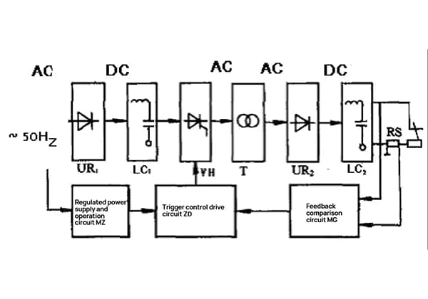
The main components and basic principle diagram of the thyristor-based arc welding inverter are shown in Figure 1.
Figure 1: Block diagram of main components and basic principle of thyristor-based arc welding inverter.
The main components and their functions of the circuit are as follows:
(1) Input rectifier (UR1): This is a common single-phase or three-phase rectifier bridge. It converts 50Hz or 60Hz AC voltage into DC voltage.
(2) Input filter (LC1): The filter is composed of a gap-type inductor and a capacitor, which makes the input DC voltage relatively smooth.
(3) High-power fast thyristor group VH: It acts as a high-power, high-voltage electronic switch, inverting the DC voltage (current) into intermediate frequency voltage (current) of several kilohertz.
(4) Intermediate frequency transformer (T): It converts high voltage and low current into low voltage and high current output that is suitable for the welding process. Typically, its core material is made of ferrite, amorphous alloy, nanocrystalline alloy, or high ρ-value silicon steel.
(5) Output rectifier (UR2): It rectifies the low-voltage intermediate frequency AC into DC.
(6) Output filter (LC2): It makes the DC voltage with high ripple coefficient relatively smooth. However, it is different from the input filter because the ripple frequency of the input filter is 100Hz to 300Hz, while the ripple frequency of the output filter is several kilohertz to tens of kilohertz, so an intermediate frequency filter device is needed.
(7) Trigger control driving circuit (ZD): It generates trigger control driving pulse signals for the thyristor group VH.
(8) Voltage stabilizing power supply and operation circuit (MZ): It provides a voltage stabilizing power supply for the trigger control driving circuit, operation circuit, and given-feedback comparison circuit.
(9) Feedback comparison circuit (MG): It takes a negative feedback signal of arc voltage and current from the output circuit in a certain proportion, compares and amplifies it with the given (standard) voltage, and provides control signals for the trigger driving circuit to change the output voltage and current to meet the requirements of the welding process.
Characteristics and Applications
The use of high-power thyristors as switching elements: In earlier times, high-capacity, high-voltage, and high-performance thyristors were already being produced, usually requiring only one or a pair of thyristors with low cost.
However, due to the limitation of thyristor turn-off time, the rated operating frequency of the inverter is usually only between 2000Hz and 5000Hz. Within this frequency range, there is significant noise, especially during AC arc welding, where the arc noise has a certain impact on the human body.
Common characteristics shared with general arc welding inverters: Compared with arc welding generators and arc welding rectifiers, the thyristor-based arc welding inverter has the advantages of high efficiency, energy saving, light weight, small volume, high power factor, and good arc welding performance.
Transistorized Arc Welding Inverter
What Is a Transistorized Arc Welding Inverter?
A transistorized arc welding inverter is a type of arc welding inverter that uses transistors as the power switches. It belongs to the current-controlled type of arc welding inverter. The emergence of the phase angle-controlled arc welding inverter undoubtedly helped to drive the revolution of arc welding power sources. However, as mentioned earlier, the limitations of thyristors as high-power electronic switches, such as slow switching speed, low inversion frequency, poor control performance, and noise, have restricted their further development.
Therefore, scientists and engineering technicians began to search for a high-power electronic switch component with fast switching speed and good control performance to overcome the shortcomings of thyristor-based arc welding inverters. Thus, in the development history of inverter arc welding power sources, the inverter power switch components have evolved from thyristors to GTRs, and later to MOSFETs and insulated gate bipolar transistors (IGBTs), among others.
An inverter that uses transistors (or transistor groups) as high-power electronic switch components and utilizes current control while possessing the electrical properties required for arc welding processes is called a current-controlled arc welding inverter, commonly known as a transistorized arc welding inverter.
Main Components and Basic Principles
Main components and their functions
The main components and operating principles of a transistorized arc welding inverter circuit are shown in Figure 2. The entire core circuit can be divided into two major parts: the inverter main circuit and the drive control circuit.
Figure 2: Schematic diagram of a transistorized arc welding inverter
(1) Inverter main circuit: This includes the power supply system, electronic power system, and welding arc, which convert and transfer energy from the power grid to the load (arc) circuit (including the inverter main circuit).
(2) Drive control circuit: This includes the electronic control system (electronic control circuit, transistor group driver, voltage regulator, program control circuit) and arc welding characteristic circuit (feedback detection circuit M, given circuit G, comparison circuit, amplifier N).
The drive control circuit provides rectangular wave pulse voltage, which is amplified by the drive circuit to ensure that the high-voltage switch, a group of high-power transistors, has a sufficiently large base current to achieve saturation conduction and reduce the voltage drop. This is crucial for current-controlled transistors.
The rectangular wave pulse voltage is provided by a clock oscillator circuit or a constant pulse width generator. With the help of feedback detection circuit, given circuit, comparison circuit, and amplification circuit, etc., closed-loop control of the transistorized arc welding inverter is achieved, and the required external characteristics and adjustment characteristics (process parameter adjustment), dynamic characteristics, and output pulse waveform are obtained.
Basic Working Principle
Essentially, a transistorized arc welding inverter is also a type of switch-mode constant voltage and current (CV/CC) welding power source.
From a basic principle standpoint, it can be traced back to the magnetic amplifier-type, thyristor phase-controlled arc welding rectifiers, and transistor-switched arc welding rectifiers introduced earlier, all of which are switch-mode power sources.
However, their high-power switching components are connected in series with the load circuit, and the regulation and stabilization of the output voltage and current are achieved by adjusting the voltage drop and on-off time ratio (time ratio) of the power transistor group.
Therefore, for the welding process conditions of low output voltage and high current, a large amount of power is borne by the power transistor group, resulting in low efficiency. In addition, the operating frequency of the main transformer is 50Hz, which results in a large size and weight.
In contrast, the transistorized arc welding inverter is a novel switch-mode power source, with the power transistor group working on the primary side with high voltage and low current. The operating frequency of the main transformer can reach 16-25kHz, resulting in much higher efficiency and significantly reduced size.
The most commonly used inverter frequency is 20kHz, making it another example of the “20kHz power technology revolution.”
The main characteristic of the transistorized arc welding inverter is the use of a “high-power switch transistor group” instead of “high-power thyristors” as the high-power switching components of the inverter, and the use of a “clock oscillator” and “V/W circuit” instead of a “constant pulse width generator” and “V/F circuit.”
Pulse width modulation is used for control and modulation, and closed-loop control of the transistorized arc welding inverter is achieved through feedback detection circuits, given circuits, comparison circuits, amplification circuits, etc.
The desired external and adjustment characteristics (process parameter adjustment), dynamic characteristics, and output pulse waveform are obtained as a result.
Classification, Characteristics, and Applications
Classification
The transistor arc welding inverter technology can be classified from different angles.
According to the shape of the external characteristic curve, it can be divided into constant voltage characteristic, constant current characteristic, slow drop characteristic, double step characteristic, constant current plus external drag characteristic, etc.
According to the output arc voltage and current waveform, it can be divided into DC, pulse, rectangular wave AC, etc.
According to the form of the main inverter circuit, it can be divided into single-end positive inverter main circuit, double-end positive inverter main circuit, half-bridge inverter main circuit, full-bridge inverter main circuit, and rarely used parallel (push-pull) inverter main circuit.
Features
Compared with the thyristor arc welding inverter, the transistor arc welding inverter has the following characteristics and advantages due to the better performance of high-power switch transistors:
The working frequency of the inverter is relatively high, reaching above 16kHz (usually 20kHz), which not only eliminates the influence of noise but also helps to further reduce weight and size.
The “fixed frequency modulation” (PWM) method is used to regulate and control the external characteristics, which can adjust the welding specifications parameters smoothly without the need for coarse adjustment or gear shifting, and is easy to operate.
The control performance is relatively good. The control parameters of the thyristor arc welding inverter are limited by the circuit parameters of the main circuit (such as L, C, etc.), and the turn-off is more troublesome. The transistor arc welding inverter adopts current-type control, which controls the transistor’s switch by base current, and has good control performance. There is no difficult turn-off problem, and the control is relatively flexible, with less influence from the main circuit parameters.
Field-Effect Transistor Arc Welding Inverter
What Is a Field-Effect Transistor Arc Welding Inverter?
Although the appearance of transistor arc welding inverters has increased the inversion frequency to the level of 20kHz, which is conducive to improving efficiency and reducing volume and weight, they suffer from secondary breakdown and require large current drive (current control type).
As a result, technology workers have actively sought a power switch with better performance to replace it, which is the high-power field-effect transistor (MOSFET).
It belongs to the voltage control type, known as the voltage control arc welding inverter, commonly known as the field-effect transistor (MOSFET) arc welding inverter. Only the control driving voltage and tiny instantaneous current are needed to achieve the switching control of power field-effect transistors, and the switching speed is faster with no secondary breakdown.
Main Components and Basic Working Principles
The main components and basic principles of MOSFET arc welding inverter are similar to those of transistor-type inverters. Its principle block diagram is shown in Figure 3.
Figure 3. Block diagram of the main components and principles of MOSFET arc welding inverter.
It also uses the “fixed-frequency pulse-width modulation (PWM)” regulation method. The inverter frequency of the transistor-type inverter is generally fixed at around 20kHz, while the MOSFET-type inverter usually uses 40-50kHz, but there are also frequencies above 50kHz.
The acquisition methods of its external characteristics and regulation characteristics (regulatory parameter adjustment) are also achieved by controlling the variation (adjustment) of the driving pulse width, including low-frequency modulation of the output pulse waveform.
In addition, the input rectifier filter circuit, basic types of inverter main circuit, output filter circuit, closed-loop control circuit with feedback and its principle, are all basically the same. They will not be further elaborated here.
Characteristics, Classification, and Applications
Characteristics of MOSFET Arc Welding Inverter
The characteristics of using field-effect transistor (MOSFET) as an electronic power switch are analyzed. Compared with transistor, MOSFET endows the arc welding inverter with the following prominent advantages and characteristics:
(1) Extremely small control power: MOSFET has a high DC input resistance of gate-source, and voltage control is adopted. From the perspective of power coupling, the MOSFET arc welding inverter can be controlled directly by a microcomputer through the A/D and D/A interfaces, and the control circuit can be simplified, which is the pursuit of modern control circuits.
(2) Wide reliable working range.
(3) Extremely short switching time.
(4) Relatively easy realization of multi-tube parallel operation: Because MOSFET has a positive temperature coefficient, parallel operation does not require a series current sharing resistor.
Classification and Application
MOSFET arc welding inverter can be classified according to external characteristics, as well as output DC, pulse, and rectangular wave AC types.
This type of arc welding inverter has universal significance, which can be used not only for manual welding of arc welding rods, tungsten argon arc welding, melting electrode gas shielded welding, plasma arc welding and cutting, but also for high-performance, precision welding such as mechanized welding, automated welding, and robot welding, by obtaining various external characteristics through different arc voltage, current feedback, and matching ratios.
In addition, its welding performance and multi-functionality can be greatly improved through digital and intelligent control.
Due to the limited power of MOSFET, it is usually used in small and medium power situations, especially for low power. By increasing the inverter frequency to 100-200kHz, a 100A MOSFET arc welding inverter can be made into only 3.4kg.
An IGBT (Insulated Gate Bipolar Transistor) arc welding inverter is a type of transistor-based arc welding inverter that uses field-effect transistors instead of traditional transistors as the electronic power switch. It offers several advantages, such as minimal power control, fast switching speed, no secondary breakdown, and higher inverter frequency.
However, there are also some drawbacks to using field-effect transistors, including lower production capability, higher channel resistance, lower voltage resistance, and smaller rated operating current. To address these issues, manufacturers and research units have developed IGBT power switching transistors by combining the high capacity of traditional transistors and the voltage control of field-effect transistors.
IGBT power switching transistors have larger capacity transistors and are relatively easier to produce and debug, thus quickly gaining widespread adoption and application in the industry. Welding inverters that use IGBT power switching transistors are also known as IGBT arc welding inverters, which are a type of voltage-controlled inverter. However, the inverter frequency of IGBT arc welding inverters is not as high as that of MOSFET-based inverters.
MOSFET-based and IGBT-based arc welding inverters each have their own characteristics and have become new types of welding power sources that are widely developed and promoted.
Main Components and Basic Operating Principle
The main components and basic operating principle of an IGBT arc welding inverter are shown in Figure 4. Compared to MOSFET-based and traditional transistor-based welding inverters, the IGBT inverter has a different size and basic structure, but they all use the “fixed frequency pulse width modulation” PWM control method.
Figure 4: Schematic diagram of the main components and basic operating principle of an IGBT arc welding inverter.
The main difference is that IGBT transistors are used instead of MOSFET or traditional transistors, and the inverter frequency is around 20-25kHz (while MOSFET-based inverters can reach 50kHz or higher). IGBT transistors use voltage control, and a single transistor has enough capacity, so there is no need for parallel operation of multiple transistors.
The IGBT inverter’s external characteristics, regulation characteristics (standard parameter regulation), and output waveform acquisition and control are also achieved through changes (conversion, modulation) in pulse width, including low-frequency modulation of the output pulse waveform.
In terms of the basic types of the input rectifier filter circuit, the inverter main circuit (multiple types), output filter circuit, closed-loop control circuit with negative feedback, and their principles, they are essentially the same as MOSFET-based welding inverters.
Classification and Applications of Igbt Arc Welding Inverters
IGBT-based arc welding inverters can be classified according to their external characteristics, or according to their output types such as DC, pulse, and square wave AC.
Both types of welding inverters have universal significance and can be used not only for large-scale and wide-ranging welding processes such as stick arc welding, tungsten argon arc welding, melting electrode gas shielded welding, plasma arc welding and cutting, but also for high-power single/double wire submerged arc automatic welding processes ranging from 1250A to 2000A, arc air gouging, and robot arc welding, as well as dual wire MIG/MAG/pulse welding, and three-wire submerged arc welding, among others.
Soft-Switching Arc Welding Inverter
What Is a Soft-Switching Arc Welding Inverter?
The power devices of arc welding power supply work and are controlled in analog or switch mode. There are two types of switch mode arc welding power supply, hard and soft-switching. The former mainly uses pulse width modulation (PWM) control technology, and the power devices work in a forced-off (current is not zero) or forced-on (voltage is not zero) state.
Due to the existence of parasitic capacitance and inductance in the circuit, the power switch devices turn on and off at working current and voltage values that are not zero or even higher, leading to high switching losses. This loss increases proportionally with frequency, significantly reducing circuit efficiency and even causing the circuit to malfunction.
Traditionally designed arc welding inverters have difficulty in fundamentally solving these problems. However, soft-switching arc welding inverters use resonant current conversion technology, where power devices turn on or off naturally under zero voltage or current conditions.
This technology essentially overcomes the disadvantages of hard-switching arc welding power supplies, reduces switching losses to a great extent, and minimizes electromagnetic interference (EMI) and radio frequency interference (RFI).
It also reduces the weight of the inverter, increases frequency, decreases the volume of transformers, inductors, and capacitors in the circuit, reduces output ripple, and enhances power density and system dynamic performance.
Therefore, the application of soft-switching technology, especially in arc welding inverters, is increasingly widespread, taking arc welding power supply to a new level. Soft-switching arc welding inverters are a promising development in this field, and this section will focus on their discussion.
Basic Form and Operating Principle of the Soft-Switching Inverter Main Circuit
The main components and basic principles of the soft-switching arc welding inverter are similar to those of the hard-switching arc welding inverter. The main difference lies in the structure details of the inverter main circuit and the adjustment method of the control and drive circuit.
The resonant current conversion technology with soft-switching operation mode can be controlled by two methods: variable frequency control and constant frequency control. Variable frequency control circuit analysis and design are complex and susceptible to interference, and the output range is small with low utilization of magnetic components.
Constant frequency control is based on commonly used PWM, in which a resonant inductor and capacitor are connected in series in the inverter main circuit. The control system uses phase-shifted square wave to drive the switch devices, relying on the freewheeling diode to achieve soft-switching control of power devices.
In the full-bridge inverter main circuit, the power switch devices on diagonal lines are not turned on and off at the same time, but are staggered with a time interval to achieve zero current turn-off or zero voltage turn-on. The output voltage or current control is achieved by adjusting the duty cycle of the bridge.
This control method is relatively easy to design, has a larger output range, and a relatively simple circuit structure, making it more suitable for arc welding inverter applications.
Basic Form of Soft-Switching Inverter Main Circuit
Currently, there are several common basic forms of soft-switching inverter main circuit, including:
Zero-current-switching (ZCS) resonant inverter main circuit.
Zero-voltage-switching (ZVS) resonant inverter main circuit.
Multi-resonant converter (MRC) inverter main circuit.
Series-resonant inverter main circuit.
Parallel-resonant inverter main circuit.
DC bus resonant inverter main circuit.
Phase-shift control resonant inverter main circuit.
Operating Principle of Soft-Switching Inverter Main Circuit
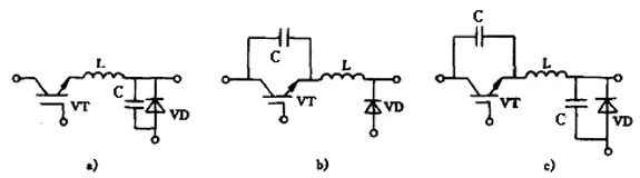
To choose the right soft-switching inverter main circuit for arc welding power supply, it is necessary to introduce in detail the following four basic soft-switching inverter main circuits:
Figure 6: Zero Current Switching (ZCS), Zero Voltage Switching (ZVS), and Multi-Resonant Circuit (MRC) Switching Circuits. a) ZCS b) ZVS c) MRC
(1) Zero Current Switching (ZCS) Resonant Inverter Main Circuit
As shown in Figure 6a, ZCS refers to using the current waveform on the auxiliary LC resonant element and the power devices to make the power devices naturally turn off under zero current conditions, achieving natural commutation of the devices.
(2) Zero Voltage Switching (ZVS) Resonant Inverter Main Circuit
As shown in Figure 6b, ZVS refers to using the voltage waveform on the auxiliary resonant element inductor and capacitor and the power devices to reduce the output capacitance voltage of the power devices to zero before turning on the devices, creating zero voltage conditions for turning on the devices and eliminating the switching losses related to the parasitic output capacitance of the devices, thereby greatly increasing the switching frequency.
However, ZVS has two drawbacks. One is the large voltage stress on the device, which is proportional to the load range, making it difficult to achieve ZVS for a wide range of loads. The other is caused by the rectifying diode oscillating with the resonant capacitor.
If it is a damping oscillation, it will cause a large power loss at high frequencies. If it is a non-damping oscillation, it will have a disadvantageous effect on the voltage gain of the inverter and may cause closed-loop oscillation.
(3) Multi-Resonant Inverter Main Circuit
As shown in Figure 6c, the multi-resonant inverter main circuit refers to combining the characteristics of ZVS and ZCS in a single switching structure. The resonant capacitor is both in parallel with the switching device and in parallel with the diode, making both the switching device and the diode zero voltage switches.
The main advantage is that all major parasitic parameters (output capacitance of the power device, junction capacitance of the diode, leakage inductance of the transformer, etc.) are integrated into the resonant circuit, making all devices in the circuit conduct when the voltage is zero, thereby reducing switching losses and improving work efficiency.
The drawback of the above three circuits is that they work on a variable frequency, resulting in high voltage and current stresses on the devices.
The series resonant inverter main circuit, parallel half-bridge and full-bridge inverter circuit, and E-class inverter main circuit are more closely related to the structure of the soft-switching arc welding inverter’s main circuit.
The E-class inverter main circuit is an improved version of the E-class amplifier circuit and is modified from the series resonant inverter. Its circuit is shown in Figure 7.
Figure 7: E-Class Inverter Main Circuit
The advantage of the E-class inverter main circuit is that it eliminates switching losses and reduces electromagnetic interference. The main disadvantage is that there is a large peak current flowing through the switch, and the switch device bears a large voltage stress.
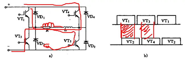
(4) Full-Bridge Inverter Main Circuit with Phase-Shift Control
Since its proposal in the late 1980s, the phase-shift controlled full-bridge soft-switching circuit has received increasing attention and become a hot topic in research and application. The phase-shift full-bridge soft-switching circuit combines two circuit topologies, resonant soft-switching and PWM, perfectly.
Resonant commutation is achieved during the power switch device switching process, ensuring lower switching losses, while after the switching device is turned on, a square wave voltage and current are provided using PWM modulation. Based on the characteristics of the switching waveform, the phase-shift controlled full-bridge soft-switching circuit can be divided into full-bridge zero voltage soft-switching and zero voltage and zero current soft-switching.
The main circuit and driving signal timing of the phase-shift controlled full-bridge inverter circuit are shown in Figure 8:
Figure 8: Phase-Shift Controlled Main Circuit and Driving Signal Timing Diagram. a) Phase-Shift Controlled Main Circuit b) Driving Signal Timing Diagram.
As the founder of MachineMFG, I have dedicated over a decade of my career to the metalworking industry. My extensive experience has allowed me to become an expert in the fields of sheet metal fabrication, machining, mechanical engineering, and machine tools for metals. I am constantly thinking, reading, and writing about these subjects, constantly striving to stay at the forefront of my field. Let my knowledge and expertise be an asset to your business.
Have you ever wondered how modern welding achieves such precision and efficiency? Arc welding inverters might hold the key. These devices transform electrical energy to create powerful welding arcs, adapting…
Have you ever considered the unsung heroes holding our machines together? In this article, we'll explore the fascinating world of mechanical connections, from the humble rivet to the mighty weld.…
Abstract: The residual stress of butt joint of X80 pipeline steel was simulated by means of finite element analysis, and the distribution of residual stress was obtained. The prediction results…
Choosing between riveting and welding for your project can be tricky. Riveting involves mechanically joining parts with rivets, ideal for minimal deformation and harsh environments. Welding, on the other hand,…
Have you ever wondered why cracks appear in metal parts during manufacturing? In this insightful blog post, we'll dive into the intriguing world of forging cracks, heat treatment cracks, and…
Ever wondered how robots are revolutionizing industries? From welding and cutting to assembling and sorting, industrial robots are transforming manufacturing processes with unmatched efficiency and precision. This article explores 13…
I. What Is Nondestructive Testing? Nondestructive testing is a general term that refers to all technical means used to detect defects or nonuniformity in an object being tested, by utilizing…
How do you choose between an orifice flowmeter and a wedge flowmeter? Both serve to measure flow, but they have distinct advantages and drawbacks. Orifice flowmeters are known for their…
Ever wonder what it takes to ensure a flawless busbar installation? This comprehensive guide will walk you through each step, from technical preparations to the final adjustments, ensuring your project…