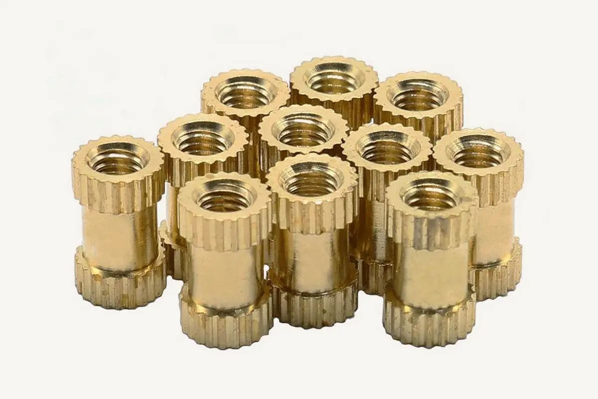
Are you tired of struggling to find the right rivet size for your projects? Look no further! In this blog post, we’ll dive into the world of rivet sizing and provide you with a comprehensive rivet size chart. Whether you’re a seasoned mechanic or a DIY enthusiast, this guide will give you the knowledge and tools to select the perfect rivet for any task. Get ready to elevate your craftsmanship and achieve strong, secure bonds every time!
If you’re a DIY enthusiast or a professional mechanic, you know how important it is to have the right tools for the job.
And when it comes to riveting, having the correct size of rivet is essential for ensuring a strong and secure bond. That’s where a rivet size chart comes in handy.
In this blog post, we’ll go over the basics of rivet sizing and provide a comprehensive rivet size chart to help you choose the right size for your project.
Whether you’re repairing a piece of machinery or working on a craft project, these rivet size chart will give you all the information you need to select the perfect rivet size for the task at hand.
So, let’s get started!
| Thread Code | Basic diameter | Internal thread | External thread | ||||||
|---|---|---|---|---|---|---|---|---|---|
| Large dia. | Medium dia. | Small dia. | Medium diameter tolerance | Small diameter tolerance | A-grade | B-grade | |||
| Medium diameter tolerance | Large diameter tolerance | Medium diameter tolerance | Large diameter tolerance | ||||||
| G1/8″×28 | 9.728 | 9.147 | 8.566 | +0.170 | +0.282 0 | 0 -0.107 | 0 -0.214 | 0 -0.214 | 0 -0.214 |
| G1/4″×19 | 13.157 | 12.301 | 11.445 | +0.125 | +0.445 | -0.125 | -0.250 | -0.250 | 0-0.250 |
| G3/8″×19 | 16.662 | 15.806 | 14.950 | +0.125 0 | +0.445 0 | 0 -0.125 | 0 -0.250 | 0 -0.250 | 0 -0.250 |
| G1/2″×14 | 20.955 | 19.793 | 18.631 | +0.142 0 | +0.541 0 | 0 -0.142 | 0 -0.284 | 0 -0.284 | 0 -0.284 |
| G5/8″×14 | 22.911 | 21.749 | 20.587 | +0.142 0 | +0.541 0 | 0 -0.142 | 0 -0.284 | 0 -0.284 | 0 -0.284 |
| G3/4″×14 | 26.441 | 25.279 | 24.117 | +0.142 0 | +0.541 0 | 0 -0.142 | 0 -0.284 | 0 -0.284 | 0 -0.284 |
| G1″×11 | 33.249 | 31.770 | 30.291 | +0.180 0 | +0.640 0 | 0 -0.180 | 0 -0.360 | 0 -0.360 | 0 -0.360 |
| G1.1/4″×11 | 41.910 | 40.431 | 38.952 | +0.180 0 | +0.640 0 | 0 -0.180 | 0 -0.360 | 0 -0.360 | 0 -0.360 |
| G1.1/2″×11 | 47.803 | 46.324 | 44.854 | +0.180 0 | +0.640 0 | 0 -0.180 | 0 -0.360 | 0 -0.360 | 0 -0.360 |
| G2″×11 | 59.614 | 58.135 | 56.656 | +0.180 0 | +0.640 0 | 0 -0.180 | 0 -0.360 | 0 -0.360 | 0 -0.360 |
| G2.1/2”X11 | 75.184 | 73.705 | 72.226 | +0.217 0 | +0.640 0 | 0 -0.217 | 0 -0.434 | 0 -0.434 | 0 -0.434 |
| G3”X11 | 87.884 | 86.405 | 84.926 | +0.217 0 | +0.640 0 | 0 -0.217 | 0 -0.434 | 0 -0.434 | 0 -0.434 |
| G3.1/2”X11 | 100.330 | 98.851 | 97.372 | +0.217 0 | +0.640 0 | 0 -0.217 | 0 -0.434 | 0 -0.434 | 0 -0.434 |
| Thread designation | Diameter over the basic surface | Reference length | Effective thread length | Axial displacement deviation of the conical internal thread basic surface (±mm) | ||||||
|---|---|---|---|---|---|---|---|---|---|---|
| Large dia. | Medium dia. | Small dia. | Basic | Max | Min | Basic | Max | Min | ||
| R1/8″×28 | 9.728 | 9.147 | 8.566 | 4.0 | 4.9 | 3.1 | 6.5 | 7.4 | 5.6 | 1.1 |
| R1/4″×19 | 13.157 | 12.301 | 11.445 | 6.0 | 7.3 | 4.7 | 9.7 | 11.0 | 8.4 | 1.7 |
| R3/8″×19 | 16.662 | 15.806 | 14.950 | 6.4 | 7.7 | 5.1 | 10.1 | 11.4 | 8.8 | 1.7 |
| R1/2″×14 | 20.955 | 19.793 | 18.631 | 8.2 | 10.0 | 6.4 | 13.2 | 15.0 | 11.4 | 2.3 |
| R3/4″×14 | 26.441 | 25.279 | 24.117 | 9.5 | 11.3 | 7.7 | 14.5 | 16.3 | 12.7 | 2.3 |
| R1″×11 | 33.249 | 31.770 | 30.291 | 10.4 | 12.7 | 8.1 | 16.8 | 19.1 | 14.5 | 2.9 |
| R1.1/4″×11 | 41.910 | 40.431 | 38.952 | 12.7 | 15.0 | 10.4 | 19.1 | 21.4 | 16.8 | 2.9 |
| R1.1/2″×11 | 47.803 | 46.324 | 44.845 | 12.7 | 15.0 | 10.4 | 19.1 | 21.4 | 16.8 | 2.9 |
| R2″×11 | 59.614 | 58.135 | 56.656 | 15.9 | 18.2 | 13.6 | 23.4 | 25.7 | 21.1 | 2.9 |
| R2.1/2”X11 | 75.184 | 73.705 | 72.226 | 17.5 | 21.0 | 14.0 | 26.7 | 30.2 | 23.2 | 3.5 |
| R3”X11 | 87.884 | 86.405 | 84.926 | 20.6 | 24.1 | 17.1 | 29.8 | 33.3 | 26.3 | 3.5 |
| R3.1/2”X11 | 100.330 | 98.851 | 97.372 | 22.2 | 25.7 | 18.7 | 31.4 | 34.9 | 27.9 | 3.5 |
| Thread designation | External thread | Internal thread | ||||||||
|---|---|---|---|---|---|---|---|---|---|---|
| Tolerance grade | Tolerance grade | |||||||||
| 2A | 2B | |||||||||
| Large dia. | Medium dia. | Small dia. | Small dia. | Medium dia. | Large dia. | |||||
| Max. | Min. | Max. | Min. | Min. | Max. | Min. | Max. | |||
| JIC thread | ||||||||||
| 7/16″×20UNF | 11.079 | 10.874 | 10.254 | 10.147 | 9.568 | 9.728 | 10.033 | 10.287 | 10.424 | 11.113 |
| 1/2″×20UNF | 12.667 | 12.461 | 11.841 | 11.732 | 11.156 | 11.328 | 11.608 | 11.875 | 12.017 | 12.7 |
| 9/16″×18UNF | 14.252 | 14.031 | 13.335 | 13.221 | 12.573 | 12.751 | 13.081 | 13.371 | 13.52 | 14.288 |
| 3/4″×16UNF | 19.012 | 18.773 | 17.981 | 17.854 | 17.12 | 17.323 | 17.678 | 18.019 | 18.184 | 19.05 |
| 7/8″×14UNF | 22.184 | 21.923 | 21.006 | 20.869 | 20.025 | 20.269 | 20.676 | 21.046 | 21.224 | 22.225 |
| 1-1/16″×12UN | 26.944 | 26.655 | 25.57 | 25.425 | 24.425 | 24.689 | 25.146 | 25.613 | 25.801 | 26.988 |
| 1-5/16″×12UN | 33.294 | 33.005 | 31.92 | 31.773 | 30.775 | 31.039 | 31.496 | 31.963 | 32.154 | 33.338 |
| 1-5/8″×12UN | 41.229 | 40.94 | 39.885 | 39.705 | 38.71 | 38.989 | 39.446 | 39.901 | 40.094 | 41.275 |
| 1-7/8″×12UN | 47.579 | 47.29 | 46.205 | 46.053 | 45.06 | 45.339 | 45.796 | 46.251 | 46.449 | 47.625 |
| 2-1/2″×12UN | 63.452 | 63.162 | 62.078 | 61.92 | 60.932 | 61.214 | 61.671 | 62.126 | 62.332 | 63.5 |
| ORFS thread | ||||||||||
| 9/16″×18UNF | 14.252 | 14.031 | 13.335 | 13.221 | 12.573 | 12.751 | 13.081 | 13.371 | 13.52 | 14.288 |
| 11/16″×16UN | 17.427 | 17.188 | 16.396 | 16.274 | 15.535 | 15.748 | 16.104 | 16.431 | 16.589 | 17.463 |
| 13/16″×16UN | 20.599 | 20.361 | 19.568 | 19.444 | 18.707 | 18.923 | 19.279 | 19.606 | 19.766 | 20.638 |
| 1″×14UNF | 25.357 | 25.095 | 24.178 | 24.036 | 23.195 | 23.444 | 23.825 | 24.221 | 24.407 | 25.4 |
| 1-3/16″×12UN | 30.119 | 29.83 | 28.745 | 28.598 | 27.6 | 27.864 | 28.321 | 28.788 | 28.979 | 30.163 |
| 1-7/16″×12UN | 36.467 | 36.177 | 35.093 | 34.943 | 33.947 | 34.214 | 34.671 | 35.138 | 35.331 | 36.513 |
| 1-11/16″×12UN | 42.817 | 42.527 | 41.443 | 41.29 | 40.297 | 40.564 | 41.021 | 41.488 | 41.686 | 42.863 |
| 2″×12UN | 50.754 | 50.465 | 49.38 | 49.225 | 48.235 | 48.514 | 48.971 | 49.426 | 49.627 | 50.8 |
| SAE thread | ||||||||||
| 5/8″×18UNF | 15.839 | 15.618 | 14.923 | 14.803 | 14.161 | 14.351 | 14.681 | 14.958 | 15.11 | 15.875 |
| 1-1/16″×14UN | 26.947 | 26.683 | 25.743 | 25.608 | 24.74 | 24.968 | 25.375 | 25.783 | 25.961 | 26.987 |
| Other U.S. standard thread | ||||||||||
| 9/16″×16UN | 14.252 | 14.013 | 13.221 | 13.101 | 12.36 | 12.573 | 12.929 | 13.256 | 13.411 | 14.288 |
| 7/8″×12UN | 22.182 | 21.892 | 20.808 | 20.668 | 19.662 | 19.939 | 20.396 | 20.851 | 21.034 | 22.225 |
| 2-1/4″×12UN | 57.104 | 56.815 | 55.73 | 55.575 | 54.585 | 54.864 | 55.321 | 55.776 | 55.976 | 57.15 |
| Note: UNC coarse thread series, UNF fine thread series, UNEF extra fine thread series, UN constant pitch series. | ||||||||||
| Thread designation | Diameter over the basic surface | Thread Length | |||
|---|---|---|---|---|---|
| Large dia. | Medium dia. | Small dia. | Effective length | Length from end of pipe to basic surface | |
| Z1/8″×27 | 10.272 | 9.519 | 8.766 | 7 | 4.572 |
| Z1/4″×18 | 13.572 | 12.443 | 11.314 | 9.5 | 5.080 |
| Z3/8″×18 | 17.055 | 15.926 | 14.797 | 10.5 | 6.096 |
| Z1/2″×14 | 21.223 | 19.772 | 18.321 | 13.5 | 8.028 |
| Z3/4″×14 | 26.568 | 25.117 | 23.666 | 14 | 8.611 |
| Z1″×11.5 | 33.228 | 31.461 | 29.694 | 17.5 | 10.160 |
| Z1.1/4″×11.5 | 41.985 | 40.218 | 38.451 | 18 | 10.688 |
| Z1.1/2″×11.5 | 48.054 | 46.287 | 44.520 | 18.5 | 10.688 |
| Z2″×11.5 | 60.092 | 58.325 | 56.558 | 19 | 11.074 |
| Thread Designation | Basic Dia. | Internal Thread | External Thread | ||||||
|---|---|---|---|---|---|---|---|---|---|
| Large Dia. | Medium Dia. | Small Dia. | Tolerance Grade | Tolerance Grade | |||||
| 6H | 7H | 6G | |||||||
| Medium Dia. Tolerance | Small Dia. Tolerance | Medium Dia. Tolerance | Small Dia. Tolerance | Medium Dia. Tolerance | Large Dia. Tolerance | ||||
| m10x1 | 10 | 9.350 | 8.917 | +0.150 0 | +0.236 0 | +0.190 0 | +0.300 0 | -0.026 -0.138 | -0.026 -0.206 |
| m12x1 | 12 | 11.350 | 10.917 | +0.160 0 | +0.236 0 | +0.200 0 | +0.300 0 | -0.026 -0.144 | -0.026 -0.206 |
| m14x1 | 14 | 13.350 | 12.917 | +0.160 0 | +0.236 0 | +0.200 0 | +0.300 0 | -0.026 -0.144 | -0.026 -0.206 |
| m12x1.25 | 12 | 11.188 | 10.647 | +0.180 0 | +0.265 0 | +0.224 0 | +0.335 0 | -0.028 -0.160 | -0.028 -0.240 |
| m14x1.25 | 14 | 13.188 | 12.647 | +0.180 0 | +0.265 0 | +0.224 0 | +0.335 0 | -0.028 -0.160 | -0.028 -0.240 |
| m12x1.5 | 12 | 11.026 | 10.376 | +0.190 0 | +0.300 0 | +0.236 0 | +0.375 0 | -0.032 -0.172 | -0.032 -0.268 |
| m14x1.5 | 14 | 13.026 | 12.376 | +0.190 0 | +0.300 0 | +0.236 0 | +0.375 0 | -0.032 -0.172 | -0.032 -0.268 |
| m16x1.5 | 16 | 15.026 | 14.376 | +0.190 0 | +0.300 0 | +0.236 0 | +0.375 0 | -0.032 -0.172 | -0.032 -0.268 |
| m18x1.5 | 18 | 17.026 | 16.373 | +0.190 0 | +0.300 0 | +0.236 0 | +0.375 0 | -0.032 -0.172 | -0.032 -0.268 |
| m20x1.5 | 20 | 19.026 | 18.376 | +0.190 0 | +0.300 0 | +0.236 0 | +0.375 0 | -0.032 -0.172 | -0.032 -0.268 |
| m22x1.5 | 22 | 21.026 | 20.376 | +0.190 0 | +0.300 0 | +0.236 0 | +0.375 0 | -0.032 -0.172 | -0.032 -0.268 |
| m24x1.5 | 24 | 23.026 | 22.376 | +0.200 0 | +0.300 0 | +0.250 0 | +0.375 0 | -0.032 -0.182 | -0.032 -0.268 |
| m26x1.5 | 26 | 25.026 | 24.376 | +0.200 0 | +0.300 0 | +0.250 0 | +0.375 0 | -0.032 -0.182 | -0.032 -0.268 |
| m27x1.5 | 27 | 26.026 | 25.376 | +0.200 0 | +0.300 0 | +0.250 0 | +0.375 0 | -0.032 -0.182 | -0.032 -0.268 |
| m30x1.5 | 30 | 29.026 | 28.376 | +0.200 0 | +0.300 0 | +0.250 0 | +0.375 0 | -0.032 -0.182 | -0.032 -0.268 |
| m33x1.5 | 33 | 32.026 | 31.376 | +0.200 0 | +0.300 0 | +0.250 0 | +0.375 0 | -0.032 -0.182 | -0.032 -0.268 |
| m36x1.5 | 36 | 35.026 | 34.376 | +0.200 0 | +0.300 0 | +0.250 0 | +0.375 0 | -0.032 -0.182 | -0.032 -0.268 |
| m39x1.5 | 39 | 38.026 | 37.376 | +0.200 0 | +0.300 0 | +0.250 0 | +0.375 0 | -0.032 -0.182 | -0.032 -0.268 |
| m42x1.5 | 42 | 41.026 | 40.376 | +0.200 0 | +0.300 0 | +0.250 0 | +0.375 0 | -0.032 -0.182 | -0.032 -0.268 |
| m27x2 | 27 | 25.701 | 24.835 | +0.224 0 | +0.375 0 | +0.280 0 | +0.475 0 | -0.038 -0.208 | -0.038 -0.318 |
| m30x2 | 30 | 28.701 | 27.835 | +0.224 0 | +0.375 0 | +0.280 0 | +0.475 0 | -0.038 -0.208 | -0.038 -0.318 |
| m33x2 | 33 | 31.701 | 30.835 | +0.224 0 | +0.375 0 | +0.280 0 | +0.475 0 | -0.038 -0.208 | -0.038 -0.318 |
| m36x2 | 36 | 34.701 | 33.835 | +0.224 0 | +0.375 0 | +0.280 0 | +0.475 0 | -0.038 -0.208 | -0.038 -0.318 |
| m39x2 | 39 | 37.701 | 36.835 | +0.224 0 | +0.375 0 | +0.280 0 | +0.475 0 | -0.038 -0.208 | -0.038 -0.318 |
| m42x2 | 42 | 40.701 | 39.835 | +0.224 0 | +0.375 0 | +0.280 0 | +0.475 0 | -0.038 -0.208 | -0.038 -0.318 |
| m45x2 | 45 | 43.701 | 42.835 | +0.224 0 | +0.375 0 | +0.280 0 | +0.475 0 | -0.038 -0.208 | -0.038 -0.318 |
| m52x2 | 52 | 50.701 | 49.835 | +0.236 0 | +0.375 0 | +0.300 0 | +0.475 0 | -0.038 -0.218 | -0.038 -0.318 |
| m60x2 | 60 | 58.701 | 57.835 | +0.236 0 | +0.375 0 | +0.300 0 | +0.475 0 | -0.038 -0.218 | -0.038 -0.318 |
| m64x2 | 64 | 62.701 | 61.835 | +0.236 0 | +0.375 0 | +0.300 0 | +0.475 0 | -0.038 -0.218 | -0.038 -0.318 |
| m72x2 | 72 | 70.701 | 69.835 | +0.236 0 | +0.375 0 | +0.300 0 | +0.475 0 | -0.038 -0.218 | -0.038 -0.318 |
To sum up, a rivet size chart is an invaluable tool for anyone working with rivets. Choosing the right size of rivet is crucial for ensuring a strong and secure bond, and using the chart provided in this blog post can help you make the right choice.
By understanding the basics of rivet sizing and consulting the chart, you can be confident that you’re selecting the perfect size for your project.
Whether you’re repairing machinery or creating a work of art, having the correct size of rivet will help you achieve the best possible results.
So, next time you’re working with rivets, make sure to refer to a reliable rivet size chart to get the job done right.

