Know The Rivet Connection Calculation: The Expert Guide
Have you ever wondered how the tiny rivets holding massive structures together actually work? In this article, we’ll unravel the fascinating world of rivet connections, exploring their types, strength calculations, and real-world applications. By the end, you’ll understand the crucial role these small components play in engineering marvels. Stay tuned to learn how rivets keep our world securely fastened!
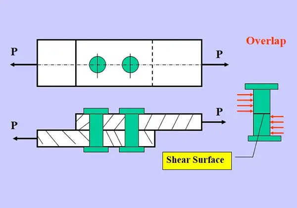
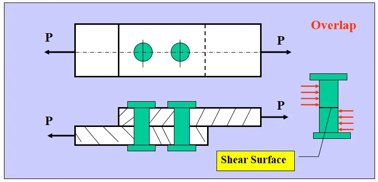
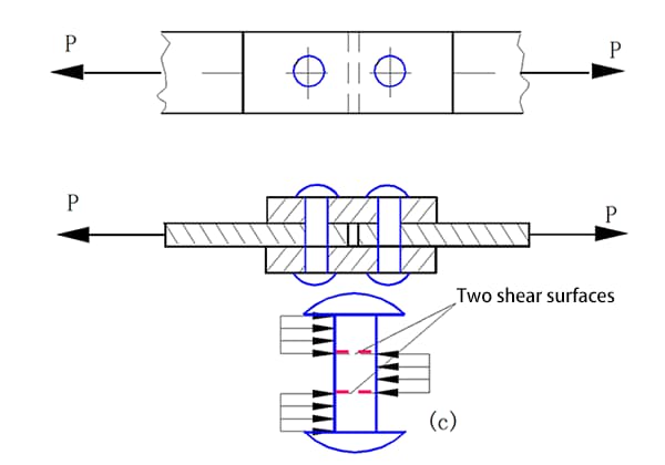
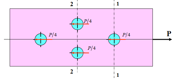
In riveted joint (as shown in the above figure), to simplify calculations, assume that:
Regardless of the method of riveting, the bending effect is not considered.
If the line of action of the external force passes through the centroid of the cross section of the rivet group, and the diameters of each rivet in the same group are the same, then the force acting on each rivet is also equal.
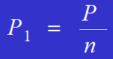
The formula for calculating the force acting on each rivet is:
Example:
A joint using four rivets is used to connect two steel plates. The material of the steel plates and rivets is the same. The diameter of the rivets is d=16mm, the size of the steel plate is b=100mm, t=10mm, P=90KN, the allowable stress of the rivets is [τ]=120MPa, the allowable yield stress is [σjy]=120MPa, and the allowable tensile stress of the steel plate is [σ]=160MPa. Calculate and check the strength of the riveted joint.
(1) Shear strength of the rivets:
The force acting on each rivet is P/4.
The shear force acting on each rivet is given by:
(2) Crushing strength of the rivets:
The force acting on each rivet due to crushing is:
The area of the rivet that is being crushed is:
(3) Tensile strength of steel plate
Thinking question:
Area of shear surface for the dowel pin A. Area of extrusion surface for the dowel pin Ajy.
Additional question:
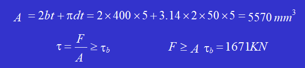
Punch a hole of the shape shown in the figure on a 5mm thick steel plate. If the shear strength limit of the steel plate material is 𝜏𝑏 = 300MPa, calculate the punching force F required for the punch press.
Solution: The area of the shear surface is
Additional question:
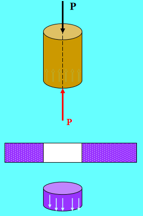
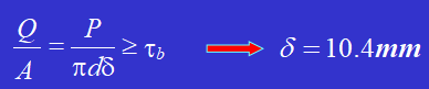
The maximum punching force of a punch press is P = 400KN, the allowable compressive stress [𝜎] of the punch material is 440MPa, and the shear strength limit of the steel plate is 𝜏𝑏 = 360MPa. Determine the minimum diameter d that the punch can punch, and the maximum thickness 𝜹 of the steel plate that can be punched.
Solution: The punch undergoes axial compressive deformation.
According to the shear failure condition of the steel plate:
Example:
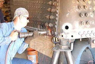
Using two steel rails to rivet into a composite beam, the connection situation is shown in figure a and b.
The cross-sectional area of each steel rail A is 8000mm, and the moment of inertia of each steel rail’s cross-sectional area relative to its own centroid is I = 1600 × 10mm. The rivet spacing s is 150mm, the diameter is d = 20mm, and the allowable shear stress [τ] is 95MPa. If the internal shear force Q of the beam is 50kN, verify the shear strength of the rivets. The friction between the upper and lower steel rails is not considered.
Solution: When the upper and lower two steel rails bend as a whole, the cross-sectional area of the upper steel rail is under compression stress, and the cross-sectional area of the lower steel rail is under tensile stress.
Due to the different bending moments on adjacent cross-sections, the normal stress at corresponding points is different, and therefore there is a tendency for longitudinal displacement along the contact surface between the upper and lower steel rails, causing the rivets to bear shear forces.
The shear force borne by each row of rivets is equal to the difference in compression (tensile) force on two cross-sections of a steel rail at a longitudinal distance of S.
Assuming that the steel rails transmit shear stress everywhere on the contact surface, the width of the contact surface is b.
Szmax represents the static moment of the cross-sectional area of a steel rail with respect to the neutral axis.
Iz is the moment of inertia of the entire cross-sectional area with respect to the neutral axis.
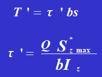
The shear stress of the rivet is:
The shear stress of the rivet satisfies the strength criteria.
The Rivet Assembly Subjected to Torsion Loads
Rivet assembly subjected to torsional loads (see Figure).
Let the centroid of the cross-section of the rivet assembly be the 0 point.
Assuming that any straight line on the steel plate (such as OA or OB) remains straight after the rotation, the average shear strain of each rivet is proportional to the distance from the center of the rivet cross-section to point O.
If the diameter of each rivet is the same, the force on each rivet is proportional to the distance from the center of the rivet cross-section to the center of the rivet assembly sectional center O, with the direction perpendicular to the line connecting the point and the center O.
Pi represents the force acting on each rivet, and ai represents the distance from the center of the cross-section of the given rivet to the centroid of the cross-section of the rivet assembly, denoted as O.
The rivet assembly subjected to eccentric lateral loads (see Figure a).
Simplifying the eccentric load P acting on the rivet assembly to the centroid point O, we obtain a force P passing through the point O and a moment m = Pe that rotates around the point O.
If the diameter of each rivet in the same rivet assembly is the same, the force P1′ caused by the lateral force P and the force P1” caused by the moment m can be calculated. The force acting on each rivet is the vector sum of P1′ and P1”. After determining the force P1 on each rivet, the shear and compression strength of the rivet with the maximum force can be checked separately.
Example:
A bracket connected by a single rivet is subjected to a concentrated force P, as shown in Figure a. The external force P is known to be 12 kN. The diameter of the rivet is 20 mm, and each rivet is subjected to single shear. Calculate the maximum shear stress on the cross-section of the rivet under the maximum force.
Solution:
The rivet assembly is symmetrical with respect to the x-axis, and the center of rotation is at point O, which is the intersection point of the line connecting rivet 2 and rivet 5 with the x-axis.
1. Simplifying the force P to point O, we have:
P = 12 kN.
m=12 0.12=1.44KN.m
2. Under the action of the force P passing through the center of rotation, and considering that each rivet has the same diameter and material, the force on each rivet is equal.
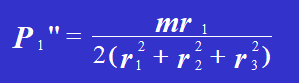
3. Under the action of the moment m, the force that each rivet bears is proportional to the distance from the rivet to the center of rotation.
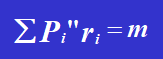
According to the balance equation:
Solving the equation, we get:
Therefore,
4. Draw the force diagram of each rivet and combine vectors Pi’ and Pi” to obtain the total shear force acting on each rivet, including its magnitude and direction. It can be concluded that rivet 1 and rivet 6 bear the maximum force, with the value of the maximum force being:
The shear stress on the cross-section of the rivet is:
As the founder of MachineMFG, I have dedicated over a decade of my career to the metalworking industry. My extensive experience has allowed me to become an expert in the fields of sheet metal fabrication, machining, mechanical engineering, and machine tools for metals. I am constantly thinking, reading, and writing about these subjects, constantly striving to stay at the forefront of my field. Let my knowledge and expertise be an asset to your business.
Have you ever considered the unsung heroes holding our machines together? In this article, we'll explore the fascinating world of mechanical connections, from the humble rivet to the mighty weld.…
Why do aircraft use rivets instead of welding? The answer lies in the unique challenges of aerospace engineering. Riveting offers greater stability and reliability, essential for the thin, lightweight materials…
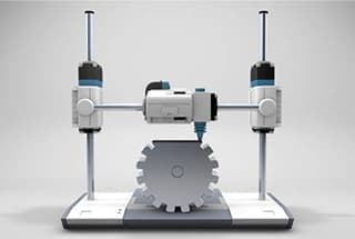
Imagine creating anything you want, layer by layer, right at your desk. Welcome to the world of 3D printing! This revolutionary technology, also known as additive manufacturing, builds objects by…
Are you tired of struggling to find the right rivet size for your projects? Look no further! In this blog post, we'll dive into the world of rivet sizing and…
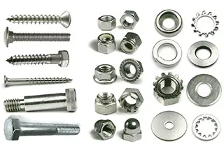
Have you ever wondered what holds our world together, from towering skyscrapers to everyday gadgets? This blog post will unravel the fascinating world of fasteners, exploring their types, uses, and…
Have you ever wondered how everyday objects are meticulously crafted from metal? This article unravels 444 essential concepts in mechanical manufacturing, from riveting techniques to the nuances of welding machines.…
Imagine a material that remembers its shape even after being twisted, bent, or stretched. Shape memory alloys (SMAs) do just that, transforming engineering across various fields. This article explores how…
Imagine transforming your everyday plastic items into durable, high-strength components simply by embedding tiny copper nuts. This blog post explores the fascinating world of hot melt copper nuts, revealing their…
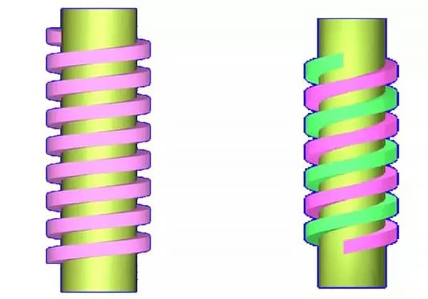
What causes threaded fasteners to loosen, and how can it be prevented? This article explores the common reasons behind loose connections, such as vibration, impact, and variable loads, and provides…