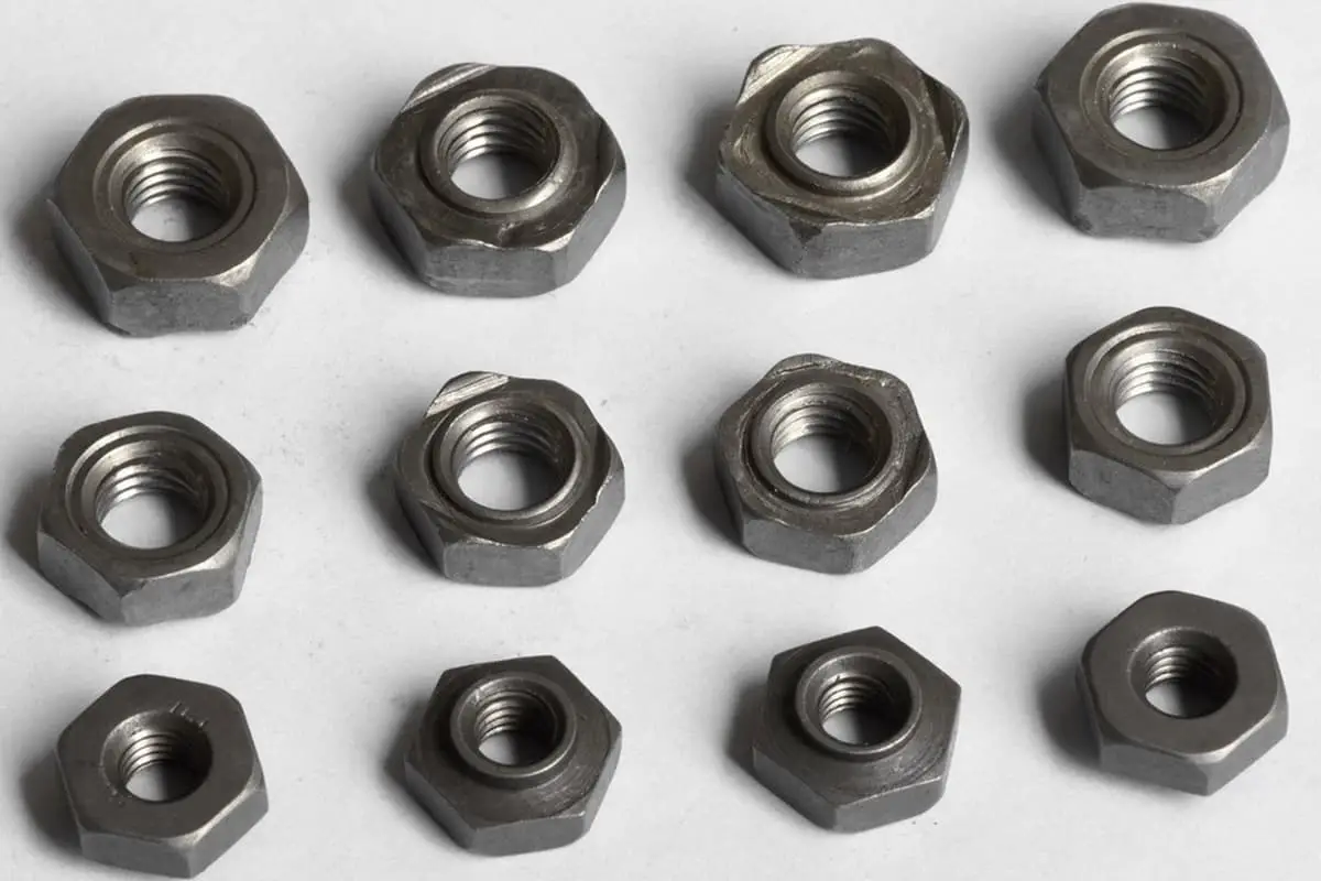
Weld Nut and Weld Stud Tightening Checks (Testing & Inspection)
Ever wondered how the integrity of welded nuts and screws in your car is ensured? This article reveals the meticulous process of quality checks and inspections that keep your vehicle safe and reliable. Learn how various tests and standards are applied to guarantee the strength and durability of these crucial components.
The tightening apparatus for weld nuts and weld screws necessitates assurance of quality during the installation process. Ensuring the integrity of these components is crucial to maintaining the overall reliability and safety of the assembled structure. To evaluate the weld quality and process reliability, it is essential to monitor the installation strength throughout the procedure. This continuous monitoring helps in detecting any deviations or anomalies that could compromise the weld’s integrity.
To further substantiate the reliability of the installation process, additional quality assurance measurements can be integrated into the production workflow. These measures may include real-time data collection and analysis, automated inspection systems, and statistical process control (SPC) techniques. By incorporating these advanced quality assurance methods, manufacturers can potentially obviate the need for subsequent inspections of weld nuts and weld screws, thereby streamlining the production process and ensuring consistent quality.
1. Overview
This standard document addresses the tightening of welded nuts and studs on steel plates and outlines the installation process for bolts. It details the welding installation conditions for the entire vehicle. Appropriate departments are responsible for these inspections. Methods not mentioned in the document should not be used.The manufacturing department requires process inspection. In the event of quality issues, the Quality Department can increase random inspections. For improvements in quality and system, and in response to quality issues, destructive testing of the vehicle frame is necessary.
2. Other applicable documents
MBN 73B – Hexagonal Nuts
MBN 73C – Square Nuts
MBN 75 – Threaded Weld Studs
MBN 10176 – Hexagonal Nuts with Flange
MBN 10369 – Round Nuts
MBN 10390 – Dome-shaped Round Nuts
MBN 10391 – Weld Studs with Welding Ring
N13008 – Flanged Nuts
DIN EN ISO 14270 – Sample Sizes and Testing Procedures for Mechanical Stripping of Weld Spots and Seams
DIN EN ISO 14272 – Sample Sizes and Testing Procedures for Cross Tensile Testing of Weld Spots
DIN EN ISO 14273 – Sample Sizes and Testing Procedures for Shear Testing of Weld Spots and Seams
3. Use of Abbreviations, Definitions, and Symbols
Boundary Weld: A joining weld is an incomplete fusion weld, where the stud merely adheres to the metal component without the required strength.
4. Material and Cycle Specifications
To control materials and cycles, all materials, methods, processes, parts, and systems should comply with the applicable legal specifications.
5. Description
The following content can only be applied to steel plate welding.
6. Installation Categories
Steel Plate Nuts
Category A
Category B
Styles
Square Nut (MBN 73C or DIN 928)
Hexagonal Nut (MBN 73B or DIN 929)
Round Weld Nut (MBN 10369)
Style A Style B
Hexagonal Nut with Flange (MBN 10176)
Round Nut
Weld Stud
Class A
Class B
Example: MBN 75MBN 10391
7. Non-Destructive Testing
7.1 Description of Procedure Sequence
All welds identified as defective through parameter monitoring (such as color marking) must be repaired. Additional test samples must be separated from the specified random test pieces being produced. Relevant process documents must be referred to when inspecting weld studs and weld nuts. The inspection department needs to record the inspection process in detail, including the methods used to identify defects in the test pieces.
7.2 Visual Inspection
7.2.1 Inspection Process
Visual inspections must comply with established evaluation standards. These inspections should be conducted by trained inspectors under appropriate distance and lighting conditions to ensure accuracy and consistency.
7.2.2 Inspection Records
Visual inspections must be meticulously recorded in a checklist. Any confirmed defects, such as weld points trending towards the edge, must be immediately addressed and corrected within the production system or welding equipment to prevent recurrence.
7.2.3 Evaluation Standards
The inspection of weld nuts must adhere to the standards outlined in the table below. These standards ensure that all welds meet the required quality and safety criteria.
Serial Number
Evaluation Criteria:
Example
1
Missed welds of studs/nuts
2
Damage or contamination of studs/nuts (including weld spatter and thread damage)
3
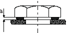
The gap is inappropriate h > 0.1m
4
Deviation from the center position Nuts must not obstruct the installation of bolts.
Reference values: For nuts with M ≤ 5, S should be ≤ 1mm. For nuts with M ≥ 6, S should be ≤ 2mm. For arched round nuts, S should be < 0.8mm.
By adhering to these standards, the quality and reliability of the welds can be maintained, ensuring the safety and performance of the final product.
7.3 Torque Testing
7.3.1 Welded Nuts
External Inspection
Before conducting torque testing on welded nuts, an external inspection is mandatory. This inspection must adhere to the standards specified in section 7.2.3. The purpose of this inspection is to identify any visible defects or irregularities that might affect the integrity of the weld or the performance of the nut during torque testing.
Torque Testing Procedure
Torque testing is a critical step to ensure the strength and reliability of welded nuts. The following steps outline the proper procedure:
Selection of Torque Wrench: Utilize a torque wrench that is calibrated and falls within the appropriate testing range for the specific type of welded nut being tested.
Application of Torque: Gradually apply torque to the nut. It is essential to increase the torque steadily to avoid sudden stress that could lead to premature failure.
Observation of Weld Seam: Carefully monitor the weld seam during the application of torque. The primary focus is to detect any signs of shearing or cracking.
Assessment of Strength: If the weld seam shears or cracks before reaching the minimum specified torque, the welded nut is considered to have insufficient strength and fails the test.
Testing Standards
The detailed standards and procedures for torque testing of welded nuts are provided in section 7.3.3. These standards outline the specific torque values, testing conditions, and acceptance criteria that must be met to ensure the welded nuts are fit for use.
Torque Measurement
M4
6 Nm
M5
8 Nm
M6
14 Nm
M8
32 Nm
M10
70 Nm
M12
100 Nm
Note: Torque inspection must be conducted on square and hexagonal nuts, while the thickness of the steel plate need not be considered for arch-shaped and round nuts.
7.3.2 Welding Studs
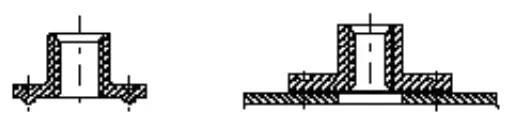
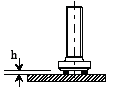
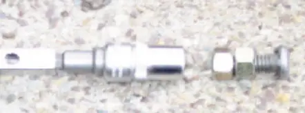
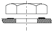
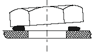
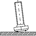
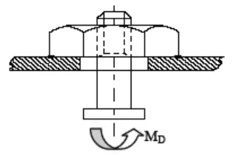
During the torque inspection process, first tighten the two nuts on the welding stud (as shown in Figure 1), then apply a predetermined Mtest inspection torque with a suitable torque wrench, thereby subjecting the nut to a torsional load (as shown in Figure 2).
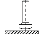
Figure 1: Side View of the Weld Stud
Figure 2: Inspection Equipment (Welding Stud, Two Nuts, Torque Wrench)
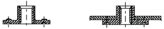
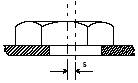
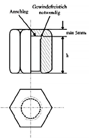
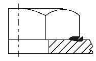
Subsequently, remove the two nuts. It’s plausible to employ an appropriate nut (as shown in Figure 3). Install the nut fully, then perform a torque check.
Figure 3: Selectable Nut (h: Depending on Actual Conditions)
7.3.3 Evaluation Criteria
Following torque inspection, the installation of screws and nuts must be assessed based on the descriptions provided in the table below.
Serial Number
Assessment Criteria
Example
1
Screws or nuts must not be loose
2
Weld seams cannot exhibit separation
3
Weld seams must not be damaged (cracked)
7.3.4 Torque Testing of Circular Nuts MBN 10369 and MBN 10390 (Arch Nuts)
Before conducting torque tests on the circular nuts, visual inspections must be performed first as specified in section 7.2.3. Start by screwing a bolt into the circular nut using a torque wrench with an appropriate torque range.
During the test, the nut is subjected to a torque by the screw. If a crack appears at the seam before reaching the minimum torque, it is deemed insufficient in strength. The testing standard is in section 7.3.3.
Minimum torque for M5 circular nut: 8Nm
Minimum torque for M6 circular nut: 14Nm
Minimum torque for M8 circular nut: 32Nm
Minimum torque for M10 circular nut: 70Nm
Minimum torque for M20 circular nut: 100Nm
7.3.5 Torque Testing of Grounding Nuts
Before conducting torque tests, visual inspections need to be performed first as dictated in section 7.2.3. Begin by screwing a bolt into the ground nut using a torque wrench with an appropriate torque range.
During the test, the nut is subjected to a torque by the bolt. If a crack appears at the seam before reaching the minimum torque, the strength is deemed insufficient. The testing standard is in section 7.3.3.
Torque for M6 grounding nut: 14Nm
Torque for M8 grounding nut: 27Nm
7.3.6 Torque Testing of Inaccessible Nuts
For nuts installed in cavities that do not require regular testing, they can be tested using headless screws. Screw the headless bolt into the nut, and then use a torque wrench with an appropriate torque range to test the nut’s torque.
If a crack appears in the nut before reaching the minimum torque, the strength is deemed insufficient. The testing standard is in section 7.3.3.
Torque Measurement
M4
4 Nm
M5
5 Nm
M6
8 Nm
M8
20 Nm
M10
50 Nm
M12
80 Nm
Note: Enhanced screws may be used if necessary.
8. Destructive Testing
Destructive testing is a specialized inspection method performed on vehicle frames to enhance quality and investigate quality issues. This type of testing involves intentionally damaging or destroying the component to assess its performance and integrity under stress.
8.1 Destructive Testing of Grounding Nuts
Before conducting destructive testing on grounding nuts, a visual inspection must be performed as standardized in Section 7.3.3.
Preparation: Use appropriate tools to strip the welded steel plate from the grounding nut.
Inspection: Check if 80% or more of the welding circumference is welded.
Note: 80% welding is considered sufficient for grounding purposes.
8.2 Destructive Torque Testing
Destructive torque testing involves using a torque wrench with an appropriate torque range to determine the torque required to unscrew the nut. The minimum separation torque of the weld is listed in Table 6.6.
8.2.1 Destructive Torque Testing of Round Nuts MBN 10369 and MBN 10390 (Arch Nuts)
Procedure: The testing method for round nuts is similar to non-destructive testing (see Section 7.2.3).
Application: Apply torque to the nut using a screw until the weld fails.
Tool: Use the same torque wrench as specified in Section 9.
8.2.2 Welding Stud Destructive Torque Testing
Procedure: The testing method for welding studs is similar to non-destructive testing (see Section 7.3.2).
Application: Apply torque to the nut using a screw until the weld fails.
Tool: Use the same torque wrench as specified in Section 9.
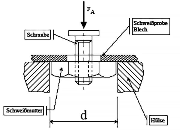
8.3 Compression Test
8.3.1 Test Sequence
Equipment: The compressive strength of the testing equipment must be adequate to measure the separated weld.
Comparison: The force $$ F_A $$ must be compared with the minimum force value listed in Table 8.4.
Evaluation: Additionally, the fracture surface must be evaluated to determine if a complete weld point was formed.
8.3.2 Testing Equipment
Hexagonal Nut
Square Nut
Diameter (mm)
Plate Thickness (mm)
Length (mm)
M3
10
2
40
M4
M4
12
M5
M5
13
M6
M6
14
M8
18
M8
21
M10
23
M12
M10
27
M14
M12
31
M16
M14
33
For components not listed in the table, such as round screws or nuts, the inspection equipment must be similar to the above.
8.4 Force Inspection List
The components mentioned in section six.
Thread Diameter
Plate Thickness
Compressive Force
M4
0.75 1.0 1.5
>1.3kN
M5
0.75 1.0 1.5
>2.0kN
M6
1.0 1.5 2.5
>2.5kN
M8
1.0 2.0 3.0
>3.0kN
M10
1.25 2.0 3.0
>4.0kN
7/16’’
1.25 2.0 3.0
>5.0kN
M12
1.5 2.0 3.0
>6.0kN
Excessive pressure that extends beyond the scope needs to be agreed upon with the relevant responsible departments.
8.5 Peel Test Inspection
The peel test inspection is a crucial method for evaluating the integrity of welded steel plate nuts. This method involves peeling the nut off the steel plate using appropriate tools such as a hammer, chisel, or tension testing equipment. The objective is to ensure that the weld points maintain their dimensions and integrity post-welding.
Procedure:
Peeling the Nut: Using suitable tools, carefully peel the nut from the steel plate.
Inspection of Weld Points: Examine each weld point to verify that the dimensions of the weld point on the peeled steel plate match the pre-weld dimensions. For example:
A weld point with a pre-weld diameter of 24mm should maintain a minimum diameter of 24mm post-weld.
A weld point with pre-weld dimensions of 3x8mm should maintain a minimum dimension of 3x8mm post-weld.
Acceptance Criteria:
Spot Welds: The weld seams are deemed acceptable if they meet the following conditions:
3 out of 4 spot welds meet the requirements.
2 out of 3 spot welds meet the requirements.
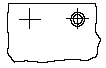
8.6 Special Metal Cross-Section Inspection
In certain special cases, a metal cross-section inspection is utilized to assess the fastening state of bolts and nuts. This method provides a detailed view of the internal structure and integrity of the fastening.
Procedure:
Special Training: This inspection must be conducted by personnel who have received specialized training.
Training Guidelines: The training must be provided by an authorized welding engineer or a certified welding expert.
Importance:
This inspection method is critical for ensuring the reliability and safety of the fastening in applications where standard inspection methods may not suffice.
9. Torque Test Table
As mentioned in Section 6, for the parts.
Destructive Testing
Non-Destructive Testing
Thread Diameter
Plate Thickness
The torque setting in the welding system.
Monitoring the torque during the part inspection process, which is related to the thickness of the plate.
M4
0.7 1.25 1.5
13 Nm 13 Nm 16 Nm
6 Nm 8 Nm 8 Nm
M5
0.7 1.25 1.5
20 Nm 29 Nm 29 Nm
8 Nm 10 Nm 10 Nm
M6
0.8 1.5 2.0
24 Nm 33 Nm 34 Nm
14 Nm 20 Nm 20 Nm
M8
1.0 2.0 3.0
58 Nm 61 Nm 60 Nm
32 Nm 38 Nm 38 Nm
M107/16’’
1.25 2.0 3.0
112 Nm 133 Nm 125 Nm
70 Nm 90 Nm 90 Nm
M12
>1.5
140 Nm
100 Nm
Note: The inspection standard in 6.2.3 is specifically for thin steel plates.
10. Inspection Document
The inspection of random samples must be recorded. The results of random inspections must be preserved for a specified period.
10.1 Remedial Measures for Defects
If defects are discovered during the inspection process, they must be immediately rectified. Additionally, the relevant systems must be inspected or corrected.
All vehicles currently experiencing the same issues must be repaired. Defective rivet nuts must be removed, and to secure new screws or nuts, the surface of the plate must be kept clean and flat.
For individual cases where screws and nuts cannot be replaced, suitable repair methods must be established through QPQ (Quench-Polish-Quench) and EP/CSV (Electropolishing/Chemical Surface Treatment).
11. Inspection Tools
The inspection department also needs to check the inspection tools.
The torque wrenches used must meet the following conditions:
Torque work difference within 10% of the inspection range
As the founder of MachineMFG, I have dedicated over a decade of my career to the metalworking industry. My extensive experience has allowed me to become an expert in the fields of sheet metal fabrication, machining, mechanical engineering, and machine tools for metals. I am constantly thinking, reading, and writing about these subjects, constantly striving to stay at the forefront of my field. Let my knowledge and expertise be an asset to your business.
Have you ever considered the unsung heroes holding our machines together? In this article, we'll explore the fascinating world of mechanical connections, from the humble rivet to the mighty weld.…
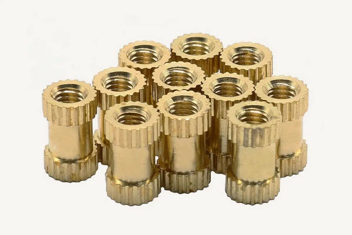
Imagine transforming your everyday plastic items into durable, high-strength components simply by embedding tiny copper nuts. This blog post explores the fascinating world of hot melt copper nuts, revealing their…
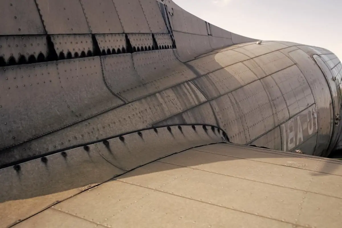
Why do aircraft use rivets instead of welding? The answer lies in the unique challenges of aerospace engineering. Riveting offers greater stability and reliability, essential for the thin, lightweight materials…
Have you ever wondered why nickel is such a vital metal in our daily lives? From the coins in your pocket to high-performance alloys in jet engines, nickel’s versatility is…
Cracks during gear grinding can be a costly problem, but understanding their causes and solutions can save both time and money. This article explores why these cracks occur, such as…
Ever wondered how robots are revolutionizing industries? From welding and cutting to assembling and sorting, industrial robots are transforming manufacturing processes with unmatched efficiency and precision. This article explores 13…
Have you ever thought about the precision required in tightening flange bolts? Proper technique can prevent leaks and ensure safety in high-pressure systems. This article delves into essential methods for…
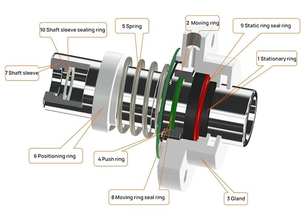
Have you ever wondered how crucial mechanical seals are in preventing leaks and ensuring the smooth operation of machinery? In this blog post, we'll dive into the world of mechanical…
I. What Is Nondestructive Testing? Nondestructive testing is a general term that refers to all technical means used to detect defects or nonuniformity in an object being tested, by utilizing…