Ever wondered how stainless steel gets that flawless, mirror-like finish? Electrolytic polishing is the secret. This process uses an electrochemical bath to remove surface material, enhancing smoothness and corrosion resistance. In this article, you’ll discover the science behind electrolytic polishing, the optimal conditions for the process, and how it’s meticulously maintained. Learn how precise adjustments in acid concentrations and current densities lead to perfect results. Prepare to understand the intricate details that ensure stainless steel’s gleaming appearance and long-lasting durability.
1. Electrolysis utilizes the polishing workpiece as the anode and an insoluble metal as the cathode. When both are immersed in an electrochemical bath and direct current is applied, selective anodic dissolution occurs, resulting in a highly smooth and glossy appearance on the stainless steel surface.
2. Electrolytic action ensures stainless steel has a consistent color inside and out, clean and bright with lasting gloss. It forms a viscous thin film on the surface, enhancing corrosion resistance.
II. Composition of the Electrolytic Solution and Process Conditions
1. Phosphoric Acid:
It both dissolves and forms a phosphate protective film on the stainless steel surface, preventing excessive corrosion. The optimal concentration is around 750mL/L.
(1) If the concentration is too high, the bath’s electrical resistance increases, the viscosity rises, leading to higher required voltage and slower leveling.
(2) If the concentration is too low, it leads to uneven corrosion on the stainless steel surface due to higher activation and lower passivation tendencies.
2. Sulfuric Acid:
As an activator, it improves the solution’s conductivity, reduces resistance, thus lowering the bath voltage, saving energy, and enhancing the dispersion capacity and anodic current efficiency. The optimal concentration is 180~210mL/L.
(1) If the concentration is too high, the surface may be excessively corroded, resulting in a uniform, dense pitting.
(2) If the concentration is too low, it leads to severe uneven corrosion.
3. Chromic Anhydride:
A strong oxidizer, it forms a passivation film on the surface to prevent corrosion, contributing to a smoother surface. The optimal concentration is 50~60g/L.
(1) If the chromic anhydride concentration is too low, it’s challenging to achieve a bright surface.
(2) If the concentration is too high, sedimentation might occur under high current, reducing current efficiency and leading to pitting and other forms of over-corrosion on the polishing surface.
4. Glycerol (Glycerin):
It plays a significant role in corrosion inhibition. It reacts with phosphoric acid to form complexes and metal derivatives, making the polished surface extremely bright and delicate. Glycerol also prevents chemical corrosion of stainless steel in the electrolyte.
(1) If the concentration is too low, despite a bright polishing surface, corrosion can make it rough.
(2) With a higher concentration, it can overcome the roughness, resulting in a bright and delicate polished surface.
(3) If the concentration is too high, excessive foam may be produced, affecting operations and wasting material.
5. Saccharin: Enhances brightness.
(1) Saccharin, when involved in cathodic processes, can be adsorbed onto metal surfaces, contributing to the brightness and shine of the polished surface.
(2) In anodic processes, saccharin forms an adsorption film on the anode surface, which protects the stainless steel surface from electrolyte erosion when there is no current. When power is applied, the electrical lines first break through the isolation film at the raised parts, initiating dissolution, while the recessed areas are effectively protected, resulting in selective dissolution for a smooth and shiny surface.
6. Current Density:
(1) At low current densities, the metal is in an activated state, with the polished surface being eroded. Anode dissolution products are minimal, and chemical dissolution dominates over electrochemical dissolution, leading to poor smoothness.
(2) When the current density exceeds the appropriate value, intense oxygen evolution occurs, causing overheating and over-corrosion on the metal surface, leading to irregular dissolution and increased electrical energy consumption.
7. Temperature:
A moderate increase in temperature can accelerate the leveling process and improve current efficiency, thereby enhancing surface smoothness and brightness.
(1) Too low a temperature increases the viscosity of the electrolyte, making it more difficult for anodic dissolution products to diffuse from the metal surface to the electrolyte and replenish the anode.
(2) Too high a temperature increases the quantity of dissolved metal, producing steam and gas in the tank that displace the electrolyte from the metal surface, paradoxically slowing down the metal dissolution rate. The decreased viscosity near the electrolyte accelerates the diffusion of dissolution products, leading to accelerated dissolution rates and impacting surface smoothness.
III. Preparation of Electrolyte Solution
The solution should be prepared according to the volume content [% (V)] or mL/L and mass content [% (wt)] or g/L in the formula, which will differ in dosage calculation.
1. Volume Content
Assuming the tank liquid volume is 1000L, the calculation of dosage and preparation steps are as follows.
a. Phosphoric acid dosage: XmL/L×1000L=XL. Measure and add phosphoric acid XL to the tank.
b. Sulfuric acid dosage: XmL/L×1000L=XL. Measure and gradually add sulfuric acid XL to the phosphoric acid while stirring.
c. Water dosage: XmL/L×1000L=XL. Place in a separate container.
d. Chromic anhydride dosage: XmL/L×1000L=XL. Add the weighed chromic anhydride to the water and stir until it dissolves into a chromic acid solution.
e. Gradually add the chromic acid solution to the phosphoric-sulfuric acid solution while stirring until uniform. The solution will appear yellow.
f. (1) Gelatin dosage: Xg/L×1000L=Xkg. Stir the weighed gelatin in hot water until uniform, then slowly add it in small batches to the phosphoric-sulfuric acid solution. This will start a strong reduction reaction and the electrolyte will turn yellow-green.
(2) Gradually add the calculated amount of glycerin to the tank while stirring. This will also start a strong reduction reaction and produce excess foam. To prevent the solution from overflowing due to foam, be especially careful when adding glycerin. The solution will also turn yellow-green. Allow it to cool undisturbed.
2. Mass Content
a. Measure the specific gravity of the phosphoric and sulfuric acids used, assuming the measured phosphoric acid density d1=1.7g/mL, sulfuric acid density d2=1.8g/mL.
b. Then, from the chemical data tables of the relative density of each acid, it can be found that: in 100g of acid solution, the phosphoric acid content P1=86.25g, sulfuric acid content P2=88g.
c. Calculate the required volume of phosphoric acid V1 and sulfuric acid V2.
V=xdo×1000/pd (L)
Where x is the mass percentage of the acid in the formula; do is the solution density, take the average value=1.65g/mL
d. Water volume=1000-V1-V2
e. Chromic anhydride dosage.
Since chromic anhydride is a solid acid, the required mass is calculated by the formula xd0×1000/100 (Kg).
f. Add the calculated amount of chromic anhydride to the required water and stir until dissolved.
g. Add the calculated amount of phosphoric acid to the chromic anhydride solution and stir until uniform.
h. Gradually add the calculated amount of sulfuric acid to the solution from step g while stirring.
3. Measuring the relative density of the solution:
After the prepared solution cools down to room temperature, measure its relative density using a hydrometer.
1. If the relative density exceeds 1.7, add an appropriate amount of water to the electrolyte, diluting it until the relative density is within the range of 1.6 to 1.7.
2. If the relative density is within 1.6 to 1.7 but the volume of the electrolyte is insufficient, replenish the required amount of phosphoric acid, sulfuric acid, and chromic anhydride according to the shortage in volume.
3. If the relative density is below 1.6 and the volume is already sufficient or slightly exceeded, heat the electrolyte to 80°C, and evaporate the moisture until the relative density reaches the range of 1.6 to 1.7.
4. Electrolytic treatment: Hang a lead plate on the cathode and a stainless steel plate on the anode. At a temperature of 70 to 80°C, apply a current density of 60 to 80A/dm² for a duration calculated at 40Ah/L.
Then, commence trial production. If pitted corrosion appears on the surface of the workpiece or the surface gloss is not satisfactory, adding chromic anhydride, gelatin, and glycerin can quickly increase the content of hexavalent chromium and trivalent chromium in the electrolyte to the required levels.
The electrolytic treatment can turn the electrolyte slightly green, indicating that a certain amount of nickel and chromium ions have dissolved into the electrolyte, enabling successful trial production.
4. Maintenance and process requirements of the electrolyte:
1. Stainless steel must be thoroughly degreased before electrolysis to prevent contamination of the bath by oil.
2. The relative density of the solution must be measured regularly during use and adjusted promptly.
3. Iron, chromium, and nickel metal elements in stainless steel dissolve into the electrolyte during the electrolysis process. Once they accumulate to a certain degree, they increase the solution’s viscosity and resistance, resulting in a lackluster surface on the stainless steel.
You can choose between two methods:
Dilute the solution with an appropriate amount of water to decrease acidity. Impurities such as iron, chromium, and nickel can form localized phosphates and precipitate. Remove the sediment from the bottom of the bath, then heat and evaporate the water to restore the original relative density.
Replace part of the solution, ideally retaining 20% of the old solution and supplementing with 80% new solution.
4. Cleaning Cathode Lead Plates: During electrolysis, the cathode lead plate surface accumulates a thick layer of impurities such as iron and nickel, hampering cathode surface conductivity and decreasing current. This hinders the anode current density and severely affects the quality of electrolysis. It is crucial to timely remove these deposits to maintain circuit fluidity.
5. Cathode to Anode Area Ratio: The cathode area is maintained at 1/2 to 1/3.5 of the anode area to inhibit the increase of trivalent chromium. Excessive trivalent chromium gets oxidized into hexavalent chromium on the anode surface. An overabundance of trivalent chromium can lead to electrolyte aging.
6. Electrode Spacing:
A large distance increases resistance, energy consumption, and can cause the solution to heat, affecting electrolysis quality.
A small distance can cause short-circuiting and blackening of the product. The optimal distance between cathode and anode is 100-300mm.
7. Cutting Power Supply During Entry and Exit of Tank: The power supply should be cut off when workpieces are put in or taken out of the tank. It is not advisable to carry or remove fixtures with electricity, as this can result in electrical sparks, cause electrolysis, and potentially ignite a mixture of hydrogen and oxygen gas aggregated on the tank surface.
8. Control Appropriate Anode Current Density: The anode current density is proportional to the dissolution of the metal. Choosing the right anode current density and controlling it within a certain anode potential range is essential for good electrolysis quality.
If the anode current density is too low, general anode dissolution occurs on the workpiece surface without any effect.
B. If the anode current density is too high, the membrane gets punctured, oxygen is rapidly released in a gaseous form, surface overheating occurs, electrolyte dilation intensifies, the membrane gets ruined, no longer exists, and electrochemical corrosion occurs.
9. Control Bath Temperature:
The temperature should be maintained within the prescribed process range to keep the leveling rate normal, reduce electrolyte viscosity, decrease anode membrane thickness, accelerate the diffusion of anode dissolution products, quicken solution convection, facilitate the detachment of retained gas bubbles on the anode, and prevent the occurrence of spots or mottling.
If the temperature is too high, it can cause the solution to overheat, accelerating the conversion of hexavalent chromium to trivalent chromium (Cr 6+ +3e→Cr 3+), which can lead to surface corrosion.
If the temperature is too low, it can increase solution viscosity and anode surface membrane thickness, inhibit the diffusion of anode dissolution products, and significantly reduce the leveling effect.
10. Optimal Ratio of Hexavalent Chromium and Trivalent Chromium: The solution should maintain a yellow-green color during the production process.
If the color is predominantly yellow, it indicates that the electrolyte contains excessive Cr 6+. Add an appropriate amount of gelatin or glycerin to partially reduce hexavalent chromium to trivalent chromium, or use a large cathode and small anode for electrolysis to generate trivalent chromium.
If the color is dark green, it signifies that the electrolyte contains excessive Cr 3+. Dissolve a proportional amount of chromic anhydride in water and add it to the solution, or use a large anode and small cathode for electrolysis to partially convert trivalent chromium into hexavalent chromium, which can also improve the quality of the solution.
5. Medical Device Co., Ltd. Process Flow
(1) Using the chemical activation method, the stainless steel is mildly etched before electrolysis to remove the passive film and activate the metal surface.
After mild etching, it should not be left in the air for too long, it should be immediately cleaned, dried, and transferred to electrolysis.
Anode Current Density A/d㎡ – (10~55) (Optimal: 15~30)
Solution Relative Density (g/cm 3) – 1.6~1.7
Duration (min) – 30~45 (Based on the size of the workpiece)
Ratio of Cathode to Anode Surface Area – (1~1.5):1
Cathode Material – Lead
IV. Analysis of Common Issues in Stainless Steel Electrolytic Polishing
1. Pockmarks on the Workpiece Surface
The primary cause is uneven current density distribution. There are several factors influencing this uneven distribution, including:
1. Inconsistent current density caused by the fixture structure. Modifying the fixture structure to ensure balanced and uniform contact with the workpiece can help. Ideally, we should increase the contact area between the fixture and the workpiece while ensuring the fixture’s quality.
2. The electrolytic polishing fluid’s specific gravity drops or exceeds the maximum value. If it surpasses the required specific gravity range, the workpiece surface is prone to pockmarks. The optimal specific gravity for the electrolytic fluid is 1.72.
3. High temperature can enhance the electrolytic fluid’s conductivity and improve the workpiece surface brightness. However, it can also lead to uneven current density distribution resulting in pockmarks.
4. Reworked parts tend to develop pockmarks during the second round of electrolytic polishing. To prevent this, the duration and current for the second round of polishing must be reduced.
5. Inadequate gas escape is mainly due to the inappropriate angle of the fixture on the workpiece. The direction of the workpiece’s holes should be upward, and the fixture angle should be adjusted to allow for easy gas dispersion during electrolytic polishing.
6. Extended electrolytic polishing time can cause pockmarks due to over-corrosion. Electrolytic polishing is a microscopic leveling process. Once the workpiece surface reaches a microscopic level of brightness and smoothness, oxidation on the part surface halts. If electrolysis continues, over-corrosion will occur, leading to pockmarks.
7. High current can result in corrosion spots. If the current passing through the part during electrolytic polishing is too high, the dissolution rate of the part surface exceeds the oxidation rate, resulting in excessive corrosion and corrosion spots.
2. Surface Burns on the Workpiece
Several factors can lead to this defect:
1. If the part is not properly positioned in the fixture before electrolytic polishing, it can loosen and wobble during the process. This looseness can lead to poor contact with the fixture or direct contact with the cathode of the fixture, causing a short circuit and subsequent burns.
2. If the operator does not conduct a short circuit test on the fixture after mounting the part and proceeds directly to electrolytic polishing, a short circuit might occur. Without testing, it is uncertain whether the mounted part is in contact with the cathode. If contact occurs, the part can burn.
3. Fixture issues can arise after prolonged use, particularly where the fixture directly contacts the part. If the contact points on the fixture become uneven, the current density borne by the part’s contact surface during electrification can vary, causing burns at areas with higher current density.
3. Parts Surface Whitening, Darkening, and Yellowing
1. Surface Whitening: The primary cause of part surface whitening is the subsequent operations, particularly during the baking process in an oven. If the temperature inside the oven is too high and the moisture in the air and on the part surface cannot be effectively expelled, the issue arises. To mitigate this, the oven temperature should be controlled at around 80±2℃, and it’s best to use an oven with a good gas circulation system.
2. Surface Darkening: This undesirable phenomenon mainly occurs where the part comes into contact with the fixture, and is predominantly due to the fixture itself. Once the previous part has finished electrolytic polishing, the part needs to be removed from the fixture in 10% dilute nitric acid. After the part is removed, the fixture must be thoroughly cleaned in water before moving on to the next part.
3. Surface Yellowing: This issue primarily appears where the part contacts the fixture. When the contact area between the part and the anode of the fixture is relatively small, the contact point can generate high temperatures and heat during electrolytic polishing. Because the contact area is not in touch with the electrolyte for cooling, slight burns may occur, resulting in yellowing. The solution to this issue mainly involves reasonable improvements to the fixture contact points or adjusting the electrolytic polishing parameters.
4. Black and Burnt Marks on the Workpiece
The formation of these marks is due to the high current needed for the electrolytic workpiece, which exceeds the maximum current that the hanger can carry. Solutions include:
1. Choosing a material with better conductivity for the hanger:
Generally, the conductivity of copper is more than 20 times that of titanium, so copper hangers have stronger conductivity than titanium hangers and are less likely to form marks. Phosphor bronze can be used, as it has good elasticity and hardness. However, the lifespan of the hanger and its resistance to corrosion, where titanium excels, must also be considered.
2. Increasing the number of hanger points:
First, determine the condition of the hanger points after electrolysis. If only minor marks form under the current conditions, increasing the number of hanger points might solve the problem.
3. Reducing the voltage appropriately:
Higher voltages speed up the light emission process, which can reduce electrolysis time and increase production efficiency. For this reason, factories generally operate at slightly higher than normal voltages. However, if the adjusted voltage is too high, it might exceed the hanger wire’s maximum load and create marks.
4. Lowering or controlling the temperature of the electrolyte:
When the electrolyte’s temperature is high, the hanger’s conductivity decreases significantly, and the current required by the workpiece increases dramatically. This can overload the hanger and create marks. In this case, lowering the electrolyte’s temperature can solve the problem. If the temperature exceeds 80 degrees and marks form, a cooling trough can be built around the electrolytic tank, with circulating water continuously cooling the electrolyte.
5. Analysis of Other Polishing Defect Causes
Polishing defects
Reasons:
Solution:
Presence of spots or small patches on the surface
Presence of oil marks or rust on the surface
Thoroughly clean to remove oil and rust.
Over-corrosion at the edges and tips of the workpiece
Excessive current, high temperature, or prolonged duration
Adjust the corresponding parameters.
White streaks on the workpiece surface
Dense electrolyte solution
Dilute with water to a density of 1.72.
Variable quality of workpieces from the same slot
Too many workpieces or mutual interference
Reduce the number of workpieces or modify the fixtures.
Excessive foam on the surface of the electrolyte
Unclean workpiece
Ensure the workpiece is thoroughly cleaned.
Dull surface with white spots
High chromic anhydride content
Consider using the environmentally friendly electrolyte solution
Exorbitant electricity costs
High current density
Consider using the environmentally friendly electrolyte solution
Sparking observed during electrolysis
Poor contact between the fixture and the workpiece
Alter the fixtures and increase the contact points.
As the founder of MachineMFG, I have dedicated over a decade of my career to the metalworking industry. My extensive experience has allowed me to become an expert in the fields of sheet metal fabrication, machining, mechanical engineering, and machine tools for metals. I am constantly thinking, reading, and writing about these subjects, constantly striving to stay at the forefront of my field. Let my knowledge and expertise be an asset to your business.
What makes titanium and stainless steel distinct from each other? While titanium boasts light weight and superior corrosion resistance, stainless steel offers durability and ease of processing. This article breaks…
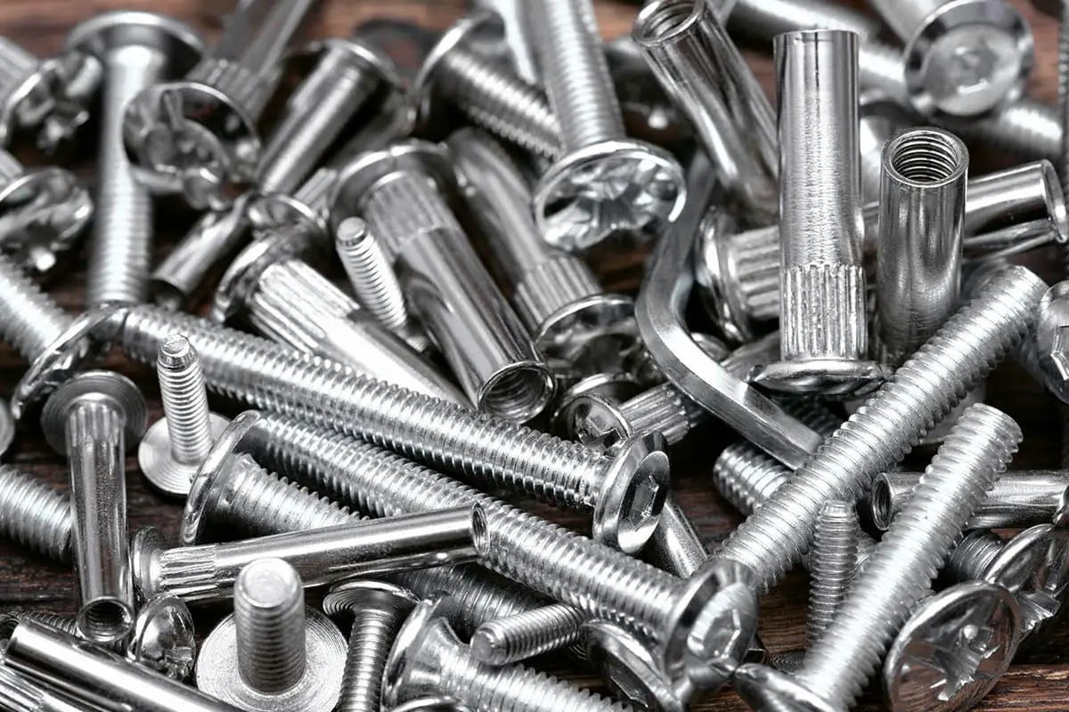
In this article, we break down the mechanical properties of SUS304 and SUS316 screws, including their tensile strength, yield strength, and torque. Learn how these tiny components withstand immense pressure…
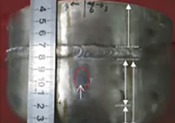
Why do 316L austenitic stainless steel alkali storage tanks crack? Despite being renowned for its durability, 316L steel can develop cracks under specific conditions. This article explores the surprising factors…
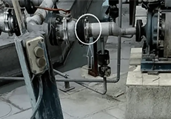
Why do stainless steel pipes, celebrated for their durability, sometimes fail under corrosive conditions? This article dives into the root causes of corrosion cracking in stainless steel pipes, focusing on…
1. Grinding The primary goal of grinding stainless steel weldments is to eliminate welding marks and achieve a surface roughness of R10um on the workpiece, in preparation for bright dipping.…
What exactly is intergranular corrosion in stainless steel, and why is it so critical to control it? This insidious form of corrosion attacks along the grain boundaries of the metal,…
Ever wondered how the gleaming finish on stainless steel is achieved? This article dives into the meticulous process of mechanical polishing, explaining techniques, tools, and best practices. From rough polishing…
Ever wonder why stainless steel castings crack so easily? This article breaks down the main causes, from poor fluidity to high thermal stress, and offers practical tips to prevent these…
Have you ever wondered how heat treatment can transform the properties of stainless steel? In this insightful article, a seasoned mechanical engineer delves into the fascinating world of stainless steel…