Sheet Metal Joining Process: The Ultimate Guide
Have you ever wondered how sheet metal parts are joined together to create complex structures? In this blog post, we'll explore the fascinating world of sheet metal joining techniques. As…
Have you ever wondered how everyday metal objects get their polished finish or rust-resistant surfaces? This article explores the intricate world of surface treatments in sheet metal fabrication. From drawing and shot blasting to various plating methods, it delves into the techniques that transform raw metal into durable, aesthetically pleasing products. You’ll gain insights into the processes and their applications, making you appreciate the hidden craftsmanship behind metalworks.
Surface treatment refers to the use of physical or chemical methods to change the surface state of a workpiece, by removing or adding certain materials to achieve the required surface properties, such as degreasing, rust prevention, decoration, oxidation resistance, etc.
1. Definition:
Drawing is a sanding process using abrasive belts to remove defects on the metal surface and create a decorative surface with a certain roughness and uniform texture.
2. Working principle:
Refer to the diagram below:

From the diagram above, it can be seen that when the worktable drives the workpiece to move (at a speed of V1), the sandpaper also rotates at a certain speed (V2), but the speeds of V1 and V2 are not equal and there is a certain speed difference. The gap between the sandpaper and the worktable has been adjusted in advance.
When the workpiece is sent between the worktable and the sandpaper, the sandpaper and the workpiece generate relative movement, and the workpiece is pulled out with a texture along the direction of motion.
3. Processing range parameters:
The maximum effective drawing width of the drawing machine (referring to the vertical size perpendicular to the drawing direction) is 850mm.
The minimum external size in the drawing direction should be larger than 235mm. If the length is not enough, a drawing fixture is needed.
The specification for using the fixture is to weld two layers of plates together, with the lower layer being a 2.0mm thick flat plate and the upper layer being a fixture with a material sleeve, but the plate thickness is slightly smaller than the thickness of the drawing material required.
The minimum applicable material thickness for the drawing machine is 0.5mm.
4. Processing characteristics:
Sandpaper has different types and specifications, and its main parameter index is the number of abrasive grains contained per square inch, such as 180#, 220# sandpaper.
The larger the value, the more abrasive grains per unit area, and the finer and shallower the resulting texture.
Conversely, the smaller the sandpaper type, the coarser the abrasive grains and the deeper the resulting texture.
Therefore, the sandpaper type must be indicated on the engineering drawing. If there is no special specification or requirement, 220# sandpaper is generally selected.
Drawing has directionality: it must be indicated on the engineering drawing whether it is a straight or horizontal drawing (indicated by double arrows).
The drawing surface of the drawing workpiece cannot have any protrusions, otherwise the protrusion will be flattened.
Protrusions are allowed on non-drawing surfaces, but the premise is that the protrusion can be avoided during drawing or a fixture is used to pad the workpiece.
Since drawing is also a grinding process that removes material from the surface of the workpiece, the drawing process should generally be prioritized over other surface treatments, and electroplating, oxidation, painting, and other treatments can be performed after drawing.
1. Shot Blasting:
Shot blasting is the process of using small and hard balls, such as metal balls, to spray the metal surface, which strengthens the surface by compression, making it harder or decorative.
2. Sandblasting:
Sandblasting uses compressed air or a high-speed rotating impeller to accelerate the abrasive and blast it onto the surface of the substrate to remove oil, rust, and residual materials, making the substrate surface clean and roughened.
It can also generate internal stress on the surface, which is beneficial for improving fatigue strength.
2.1 Types and main components of abrasive particles:
| Category | Quenched steel sand | Pure alumina | Carborundum | Standard sand |
| Main components | Fe | Al2O3 | Iron quartz | quartz |
Note: Apply anti-sticking coating on non-spray areas to facilitate the removal of the coating after spraying is completed.
2.2 Precautions for Sandblasting Process:
The surface must be clean, oil-free, and dry before sandblasting to prevent sand particles from being contaminated.
Sandblasting can cause deformation of the workpiece due to the impact of high-pressure gas, so there must be a sturdy fixture to support it.
The strong airflow should guide the sand particles to the surface to be treated, and the hardware components may have a certain influence on the sandblasting effect.
Under external forces such as bending and mold forming, the sand particles of the sandblasted workpiece may come off or cause obvious pressure marks.
There are many types and specifications of sandblasting abrasive particles. The selection should be based on the customer’s requirements and the size, shape, and hardness of the parts.
The content of this section refers to GB/T13911-92.
Therefore, there may be some differences in the representation methods compared to the export segment, but the essence of the content should be consistent. This section involves a lot of professional content.
The purpose of the author is to allow readers to have a more extensive understanding of metal plating and chemical treatment.
When encountering similar problems in future work, at least a basic understanding of their principles and methods can be obtained.
The process of depositing a layer by inducing a thermal-induced chemical reaction or vapor-phase reduction on the substrate.
The process of depositing a coating layer by evaporation and subsequent condensation of a single substance or compound in a high vacuum.
The process of treating metal parts with a solution containing an oxidant to form a thin passive protective film on the surface.
The process of forming an oxide film on the metal surface through chemical treatment.
The process of electrolyzing metal parts as an anode in a certain electrolyte to form a functional oxide film (such as protective, decorative, or other functions) on the surface.
The process of catalytically reducing metal ions in the plating solution to form a metal coating on the surface of an activated substrate.
The process of electroplating under the action of a laser.
The process of generating a coating layer in a very short time by applying an electric current.
The process of forming a uniform, dense, and well-bonded metal or alloy deposit layer on the surface of a part using electrolysis.
The process of covering a metal surface with fine metal powder in the presence of suitable chemical reagents by impacting the surface with hard small spheres.
The process of depositing a metal deposit by a replacement reaction in which one metal displaces another metal from a solution. For example: Fe+Cu2+→Cu+Fe2+.
The process of electrolytically depositing metal on a mold to manufacture or replicate metal products (which can separate the mold and the metal deposit).
The process of electroplating by superimposing a pulse current or alternating current on a direct current.
The process of directly obtaining an electroplating layer with a lustrous appearance from the plating tank under appropriate conditions.
The process of co-depositing two or more metals (including non-metallic elements) under the action of an electric current.
The process of sequentially depositing several layers of metal with different properties or materials on the same substrate.
The method of electrodepositing a thin metal layer with a high current density and short time in a specific solution to improve the bonding force between the subsequently deposited coating layer and the substrate.
The process of reducing metal ions in a solution on an electrode to form a metal phase by electrolysis. This includes electroplating, electroforming, electrolytic refining, etc.
The method of selective electroplating by moving an electrode or brush connected to the anode and able to provide the required electrolyte for electroplating on the workpiece acting as the cathode.
The process of electroplating with a periodically changing current direction.
The surface film layer containing the metal compound formed by chemical or electrochemical treatment of a metal, such as a chromate film on zinc or cadmium or an oxide film on steel.
The process of electroplating using a rack to hang parts.
The process of obtaining a composite coating layer by simultaneously depositing metal ions and insoluble non-metallic or other metallic particles uniformly suspended in the solution by electrochemical or chemical methods.
The process of electroplating using a pulse power supply instead of a direct current power supply.
The process of heating steel parts in air or immersing them in an oxidizing solution to form a usually blue (black) oxide film on the surface.
The process of electroplating at an extremely high cathode current density using special measures to obtain a high deposition rate.
The process of electroplating parts in a rotating container
The process of electrodepositing a metal coating on plastic parts.
The process of forming a difficult-to-soluble phosphate protective film on the surface of steel parts.
Among the various methods listed above, the most commonly used are chemical passivation, chemical oxidation, anodizing, electroplating, and phosphating.
A: Definition
B: Methods
The following is the representation method for metal plating and chemical treatment specified in GB/T 13911-92. It is applicable to the representation of electroplating, chemical plating, chemical treatment, and electrochemical treatment on metal and non-metal components.
When there are requirements for metal plating and chemical treatment that are not specified in this standard, it is allowed to provide explanations in relevant technical documents.
(1) Symbols for metal plating are represented in the following order:
Substrate material / plating method • plating layer name plating layer thickness plating layer characteristics • post-treatment
When the substrate material is explicitly specified in the pattern or relevant technical documents, it is allowed to be omitted.
When the plating layer is formed by multiple plating methods, if the plating method of a certain plating layer is different from the “plating method” indicated on the far left, its plating method symbol and the separator “•” should be marked in front of the plating layer name.
When there are no specific requirements for plating layer characteristics, plating layer thickness, or post-treatment, they are allowed to be omitted.
Examples:
Fe/Ep • Cu10Ni15bCr0.3mc
(Steel, electroplated with copper of 10μm or more, bright nickel of 15μm or more, micro-cracked chromium of 0.3μm or more)
Fe/Ep • Zn7 • c2C
(Steel, electroplated with zinc of 7μm or more, treated with rainbow chromate of grade 2C)
Cu/Ep • Ni5bCr0.3r
(Copper, electroplated with bright nickel of 5μm or more, ordinary chromium of 0.3μm or more)
Fe/Ep • Cu20Ap • Ni10Cr0.3cf
(Steel, electroplated with copper of 20μm or more, chemically plated with nickel of 10μm or more, electroplated with crack-free nickel of 0.3μm or more)
PL/Ep • Cu10bNi15bCr0.3
(Plastic, electroplated with bright copper of 10μm or more, bright nickel of 15μm or more, ordinary chromium of 0.3μm or more. Ordinary chromium symbol “r” is omitted)
(2) Symbols for chemical treatment and electrochemical treatment are represented in the following order:
Substrate material / treatment method • treatment name treatment characteristics • post-treatment (color)
When the substrate material is explicitly specified in the pattern or relevant technical documents, it is allowed to be omitted.
When there are no specific requirements for treatment characteristics, post-treatment, or color for chemical treatment or electrochemical treatment, they are allowed to be omitted.
Examples:
Al/Et • A • Cl(BK)
(Aluminum, electrochemical treatment, anodizing, black color, no specific requirement for anodizing method)
Cu/Ct • P
(Copper, chemical treatment, passivation)
Fe/Ct • MnPh
(Steel, chemical treatment, phosphate treatment)
Al/Et • Ec
(Aluminum, electrochemical treatment, electrolytic coloring)
(3) Representation symbols:
Substrate material representation symbols:
Metal materials are represented by chemical element symbols; alloy materials are represented by the chemical element symbols of their main components; non-metal materials are represented by internationally recognized abbreviation letters.
The representation symbols for commonly used substrate materials are shown in the table below.
| Iron, steel | Fe |
| Copper and copper alloys | Cu |
| Aluminum and aluminum alloy | Al |
| Zinc and zinc alloys | Zn |
| Magnesium and magnesium alloys | Mg |
| Titanium and titanium alloys | Ti |
| Plastic | PL |
| Silicate materials (ceramics, glass, etc.) | CE |
| Other non gold | NM |
Symbols for plating methods and treatment methods are shown in the table below:
| Method Name | english | Symbols |
| Electroplating | electroplating | Ep |
| Chemical plating | autocatalyticplating | Ap |
| Electrochemical treatment | electrochemicaltreatment | Et |
| Chemical treatment | Chemicaltreatment | Ct |
Coating layer representation symbol:
1. The name of the coating layer is represented by the chemical element symbol of the coating.
2. The name of the alloy coating layer is expressed by the chemical element symbols and content of the alloy that composes it.
The alloy elements are connected with a hyphen “-.
The alloy content is the upper limit of the mass percentage, represented by Arabic numerals written after the corresponding chemical element symbol in parentheses.
The component with a higher content is placed first. Binary alloys indicate the content of one element component, ternary alloys indicate the content of two element components, and so on.
It is allowed not to mark the content of the alloy component when it is not necessary or inconvenient to do so.
Example 1: Cu/Ep ‧ Sn(60)-Pb15 ‧ Fm
(Copper material, electroplated with Sn-Pb alloy with over 60% tin and 15μm thickness or more, hot melt)
Example 2: Al/Ep ‧ Ni(80)-Co(20)-P3
(Aluminum material, electroplated with Ni-Co-P alloy with over 80% nickel, 20% cobalt, and 3μm thickness or more)
Example 3: Cu/Ep ‧ Au-Cu 1~3
(Copper material, electroplated with Au-Cu alloy with 1-3μm thickness)
3. If it is necessary to indicate the purity of a certain metal coating layer, the mass percentage can be listed in parentheses after the element symbol of that metal, accurate to one decimal place.
Example: Ti/Ep ‧ Au(99.9)3
(Titanium material, electroplated with gold with purity over 99.9% and thickness of 3μm or more)
4. When performing multilayer coating, the name, thickness, and characteristics of each layer should be marked from left to right according to the coating order, and there should be a space of one letter width between each layer’s mark. It is also possible to only mark the name and total thickness of the final coating layer, and add parentheses outside the coating layer name to distinguish it from a single coating layer, but it must be specified or explained in relevant technical documents.
Example 1: See B.1.3 Example 1, Example 2, Example 3, Example 4, Example 5
Example 2: Fe/Ep ‧ (Cr)25b
(Steel material, electroplated with chromium on the surface, combined coating layer characterized by brightness, with a total thickness of 25μm or more, and the intermediate coating layer executed according to relevant regulations)
Coating layer thickness representation symbol:
The thickness of the coating layer is represented by Arabic numerals with a unit of μm.
The thickness number is marked after the coating layer name, and the value is the lower limit of the coating layer thickness range.
When necessary, the coating thickness range can be marked.
Example: Cu/Ep ‧ Ni5Au1~3
(Copper material, electroplated with Ni with a thickness of 5μm or more, and Au with a thickness range of 1-3μm)
Symbols for representing the names of chemical treatment and electrochemical treatment are shown in the table below.
| Process Name | English | Symbol | |
| passivation | passivaing | P | |
| oxidation | oxidation | O | |
| Electrolytic coloring | electrolytic colouring | Ec | |
| Phosphate treatment | Manganese phosphate treatment | manganesephosphatetreatment | MnPh |
| Zinc phosphate treatment | zinc phosphatetreatment | ZnPh | |
| Manganese zinc phosphate treatment | manganese zincphosphate treatment | MnZnPh | |
| Zinc phosphate calcium salt treatment | inccalciumphosphatetreatment | ZnCaPh | |
| Anodizing | Sulfuric acid anodizing | sulphuric acidanodizing | A(S) |
| Chromic acid anodizing | hromicacidanodizing | A(Cr) | |
| Phosphoric acid anodizing | phosphoric acidanodizing | A(P) | |
| Oxalic acid anodizing | oxalic acid anodizing | A(O) | |
Note: When there are no specific requirements for phosphate anodizing, it is allowed to only mark Ph (phosphate treatment symbol) or A (anodizing symbol).
Coating layer characteristics and treatment characteristics representation symbols are shown in the table below.
| English | Symbols |
| bright | b |
| semi-bright | |
| matte | m |
| satin | st |
| double layer | d |
| – | d |
| regular | r |
| micro-porous | mp |
| micro-crack | mc |
| crack-free | cf |
| porous | p |
| patterns | pt |
| blackening | bk |
| opalescence | 0 |
| sealing | se |
| composition | cp |
| hardness | hd |
| porcelain | pc |
| conduction | cd |
| insulation | i |
Note:
(1) When there are no special requirements specified, it is allowed to omit marking, such as conventional chromium plating.
(2) Refers to the coating obtained by the diffusion coating method, such as nickel sealing.
Post-treatment name representation symbols are shown in the table below.
| English | Symbol |
| passivation | P |
| phosphating(phosphate treatment) | Ph |
| oxidation | O |
| emulsification | E |
| colouring | Cl |
| flash melting | Fm |
| diffusion | Di |
| painting | Pt |
| sealing | S |
| anti-tarnish | At |
| chromate sealing | Cs |
The representation symbols for chromate treatment after electroplating zinc and electroplating cadmium are shown in the table below.
| English | Symbol | Classification | Types |
| bright chromate treatment | c | 1 | – |
| blanching chromate treatment | – | ||
| iris chromate treatment | 2 | – | |
| dark chromate treatment | – |
Color representation symbols:
1. The representation symbols for commonly used colors after electrochemical anodizing of light metals and their alloys are shown in the table below.
2. When performing color matching after electrochemical anodizing of light metals and their alloys, the color codes should be listed in the order of color matching, and “+” should be inserted in between to indicate the sequence.
3. The color and color matching requirements after electrochemical anodizing of light metals and their alloys should be based on the processed samples.
| Color | Black | Brown | Red | Orange | Yellow | Green | Blue light blue | Purple Purple Red | (Blue gray) | White | Pink | Golden yellow | cyan | silvery white |
| Letter code | BK | BN | RD | OG | YE | GN | BU | VT | GY | WH | PK | GD | TQ | SR |
Color letter codes are marked in parentheses () after the post-treatment “coloring” symbol.
Example: Al/Et‧A(s)‧Cl(BK+RD+GD)
(Aluminum material, electrochemical treatment, sulfuric acid anodizing, color matching sequence of black, red, and golden yellow).
Independent processing operation name symbols are shown in the table below.
| English | Symbol |
| solvent degreasing | SD |
| chemical degreasing | CD |
| electrolytic degreasing | ED |
| chemical pickling | CP |
| electrolytic pickling | EP |
| alkaline cleaning | AC |
| electrochemical polishing | ECP |
| chemical polishing | CHP |
| mechanical polishing | MP |
| sand blasting | SB |
| shot blasting | SHB |
| barrel burnishing | BB |
| brushing | BR |
| grinding | GR |
| viber | VI |
Example: Fe/SD (steel material, organic solvent degreasing)
1. Electroplating:
Electroplating is a surface treatment method in which a metal-containing salt solution is used to deposit the desired metal cations onto the surface of a substrate metal, which serves as the cathode, through electrolysis, forming a plating layer.
1.1 Pre-treatment before plating:
The purpose is to obtain a clean and fresh metal surface, which is necessary for obtaining a high-quality plating layer in the end. The main tasks include degreasing, rust removal, and dust removal, etc. The steps are as follows:
Step 1: Achieve a certain surface roughness requirement, which can be achieved through surface polishing and other processes.
Step 2: Degrease and remove oil, which can be achieved through solvent dissolution, chemical, and electrochemical methods.
Step 3: Rust removal, which can be accomplished through mechanical, pickling, and electrochemical methods.
Step 4: Activation treatment, which generally involves etching in weak acid for a certain period of time to activate the surface before plating.
1.2 Post-treatment after plating:
Passivation treatment:
It is a surface treatment method that involves chemical treatment in a certain solution to form a thin, solid, and high-stability film on the surface of the plating layer.
Passivation can significantly improve the corrosion resistance of the plating layer, as well as increase its surface gloss and anti-pollution capability.
Passivation treatment can be performed after plating Zn, Cu, Ag, and other metals.
Dehydrogenation treatment:
For metals such as zinc, during the electrodeposition process, in addition to depositing themselves, a portion of hydrogen will also precipitate and diffuse into the plating layer, causing hydrogen embrittlement in the plated part.
In order to eliminate hydrogen embrittlement, the plated part is subjected to heat treatment at a certain temperature for a few hours after electroplating, which is called dehydrogenation treatment.
1.3 Electroplated metals:
Zinc plating:
Zinc plating is mainly used for anti-corrosion of black metals such as steel and iron. The electroplating process of zinc can use both acidic and alkaline plating solutions, with pure zinc as the anode.
The acidic plating solution is cheap and has high current efficiency and fast plating speed, but the disadvantage is poor plating uniformity.
The alkaline plating solution is more expensive, but it has good plating uniformity.
Copper plating:
Copper plating is used as a bottom layer in the protective decorative plating system and can also be used to improve the bond strength between the substrate and the plating layer.
In addition, copper plating can also be used for carburizing of steel parts.
Nickel plating:
Nickel plating can be used as a surface coating or as a bottom or intermediate layer in multilayer electroplating.
Chrome plating:
Chrome plating has a beautiful gloss, high corrosion resistance, high hardness, and low friction coefficient, so it can be used for decoration, wear resistance, and corrosion resistance.
According to the requirements, it can be divided into protective-decorative chrome plating and hard chrome plating.
2. Electrobrush plating:
Pre-treatment before plating:
A. Surface repair. B. Surface cleaning. C. Electrocleaning. D. Activation treatment.
Brush plating of parts:
Advantages: Simple process, convenient operation, and electroplating can be done wherever the brush can reach. It is especially suitable for on-site maintenance of non-disassembled components.
Post-treatment after plating:
After brush plating, post-treatment should be carried out immediately to remove residues on the surface of the plated parts, such as water marks, residual traces of the solution, etc.
Necessary protective measures should be taken, such as drying, polishing, buffing, oiling, etc., to ensure that the brush-plated parts are intact.
3. Chemical plating:
Chemical plating is a surface treatment method in which metal ions in a solution are reduced to metal and deposited on the surface of the substrate without external current passing through, forming a plating layer.
3.1 Chemical nickel plating
3.2 Chemical copper plating
The chemical treatment method of metals is a method of forming a stable compound film on the metal surface through chemical or electrochemical means. The film formed by this chemical treatment is called a chemical conversion film.
Chemical conversion films can be divided into the following categories depending on the medium used to form the film:
1. Oxidation treatment
(1) Chemical oxidation of steel:
It refers to the process of treating steel in a solution containing an oxidant to form a uniform blue-black to black film on the surface, also known as “blackening” or “bluing” of steel.
(2) Chemical oxidation of non-ferrous metals:
Chemical oxidation of aluminum and aluminum alloys can produce oxide films with a thickness of 0.5μm4μm.
The film is porous and has good adsorption, which can be used as a base layer for organic coatings.
However, its wear resistance and corrosion resistance are not as good as those of anodic oxide films.
Chemical oxidation of magnesium alloys can obtain oxide films with a thickness of 0.5μm3μm on the surface.
Due to the thin and soft oxide film, it is easy to damage during use, so it is generally used as a base layer for organic coatings to improve the adhesion and protective performance of the coating and the substrate.
Chemical oxidation of copper and copper alloys can produce films of various colors on the surface of copper and copper alloys such as brass and bronze, which have good decorative functions.
2. Anodizing of aluminum and aluminum alloys
Anodizing refers to the method of generating an oxide film on the surface of a metal by using the metal as the anode in a suitable electrolyte under the action of an external current.
The film thickness is several tens to several hundreds of μm.
2.1 Properties and applications of oxide film on aluminum and aluminum alloy:
2.1.1 Porosity of oxide film:
The honeycomb-like porous structure of the film has good adsorption capacity for various organic substances, resins, waxes, inorganic substances, dyes, and paints, which can be used as the bottom layer of the coating layer. The oxide film can also be dyed in various colors to enhance the decorative effect of the metal.
2.1.2 Wear resistance of oxide film:
The aluminum oxide film has high hardness, which can improve the surface wear resistance of the metal. When the film layer adsorbs lubricant, its wear resistance can be further improved.
2.1.3 Corrosion resistance of oxide film:
The aluminum oxide film is stable in the atmosphere and therefore has good corrosion resistance. To improve the corrosion resistance of the film, the anodized film is usually sealed or sprayed with paint.
2.1.4 Electrical insulation of oxide film:
The anodized oxide film has high insulation resistance and breakdown voltage, which can be used as the dielectric layer of electrolytic capacitors or the insulation layer of electrical products.
2.1.5 Thermal insulation of oxide film:
The aluminum oxide film is a good thermal insulation layer with a stability of up to 1500°C. The thermal conductivity of the oxide film is very low.
2.1.6 Bonding strength of oxide film:
The bonding strength between the anodized oxide film and the substrate metal is strong and difficult to separate by mechanical methods.
Even if the film layer bends with the substrate metal until it breaks, the film layer still maintains a good bond with the substrate metal.
2.2 Anodizing Process for Aluminum and Aluminum Alloys:
2.2.1 Sulfuric acid anodizing:
This process can produce a transparent oxide film with a thickness of 5μm~20μm, which has good adsorption properties.
2.2.2 Chromic acid anodizing:
This process can produce a softer oxide film with a thickness of 2μm~5μm and low porosity.
The surface of the part can maintain its original accuracy and roughness, making it suitable for precision parts. It is applicable to sheet metal parts or general cutting parts.
2.2.3 Oxalic acid anodizing:
This process can produce a thick oxide film up to 60μm, which has good corrosion resistance and excellent electrical insulation properties.
The film can be colored with various vibrant colors depending on the alloying elements and their concentration in the aluminum. It is suitable for electrical insulation or decoration of pure aluminum materials.
2.3 Coloring and Sealing of Anodized Films:
The anodized film can be colored and sealed to obtain various colors and improve its corrosion and wear resistance.
3. Phosphating Treatment:
Phosphating is a chemical process that creates a layer of insoluble phosphate protective film on the metal surface by immersing it in a solution of phosphates containing manganese, iron, or zinc.
The porous structure of the phosphate film is firmly bonded to the substrate, and it has good adhesion, lubrication, corrosion resistance, non-stickiness to molten metals (Sn, Al, Zn), and high electrical insulation properties.
Phosphate film is mainly used as a base layer for coatings, lubrication layer for metal cold working, metal surface protection layer, insulation treatment for silicon steel sheets, and anti-stick treatment for die-casting molds.
The most common use of phosphating is as a pre-treatment before baking the coating, ensuring that the surface coating can be firmly bonded to the substrate.
In addition, some products are only phosphated or treated with a protective film, such as galvanized sheets, to protect the cut edges from rusting.
The thickness of the phosphate film is generally 5μm~20μm.
4. Chromate treatment (also known as passivation)
Chromate treatment is a method of forming a chromate film on the surface of metal or metal coating by immersing it in a chromium acid or chromium salt solution containing certain additives through chemical or electrochemical methods.
The film is composed of trivalent and hexavalent chromium compounds and is known as a chromate film or passivation layer. The chromate film has strong adhesion to the substrate, a compact structure, good chemical stability, and excellent corrosion resistance, which provides effective protection for the substrate.
Additionally, the chromate film can display a range of colors, from transparent or milky white to yellow, gold, light green, green, olive, dark green, brown, and black.
The chromate treatment process is commonly used to improve the corrosion resistance of zinc or cadmium coatings on steel, as well as to prevent corrosion on other metals such as aluminum, copper, tin, magnesium, and their alloys.
Generally, the higher the content of hexavalent chromium compounds in the chromate film, the better the corrosion resistance.
1. Anodic Oxide Film (γ-Al2O3):
1.1 Thickness of the anodic film: generally 10~30μm.
1.2 Hardness of the anodic film: the hardness of the anodic film itself is between that of crystal and corundum.
1.3 After oxidation, the aluminum surface is hard and brittle. The film may crack when the material is bent or processed. Therefore, it is important to avoid deformation or processing after forming the film.
Alternating current anodization produces a slightly more flexible film. The addition of copper can also improve the flexibility.
1.4 Corrosion resistance of the anodic film: a dense and hard anodic film has better corrosion resistance than a softer film.
When the film is thicker, the corrosion resistance improves, but there is a limit to the improvement of corrosion resistance with increasing film thickness.
The most suitable thickness for practical use is 0.02mm. The corrosion resistance of the film is closely related to the treatment method.
Reducing the number of pores, proper pre-treatment such as water resistance treatment, and removing the adhesion of the electrolyte to the film can all improve the corrosion resistance of the film.
2. Electroplating of Aluminum:
2.1 Purpose of aluminum electroplating: silver plating on the surface of aluminum can improve its conductivity. Copper, nickel, or tin plating can make it easier to solder.
Chromium plating can enhance its wear resistance, and nickel or chromium plating can be used for decoration.
In practical sheet metal fabrication, the most commonly used metal plating and chemical treatment methods are electroplating, oxidation, and phosphating.
The following will explain the impact of these three methods on our process arrangements and the precautions to be taken as a result.
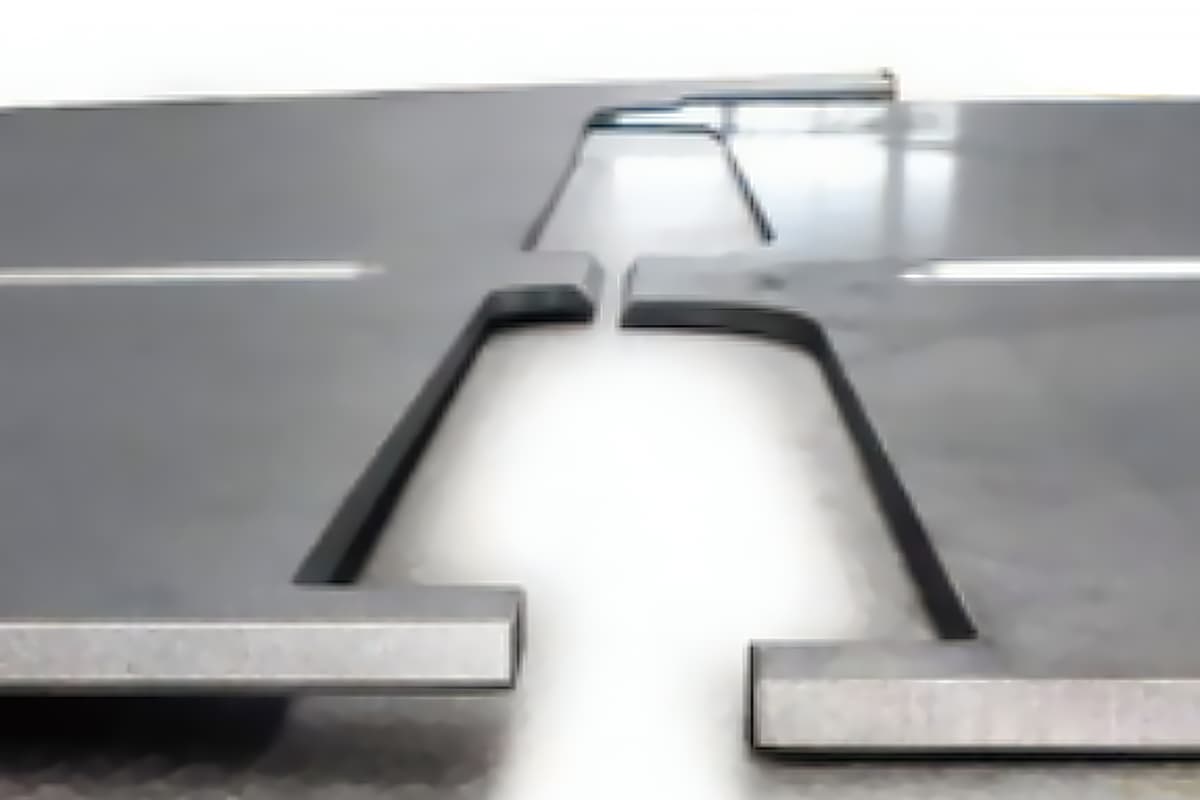
1: Crushed edge, sharp angle
Since electroplating and oxidation generally require a solution to be used, after processing, if there are blind holes or gaps in the workpiece, the solution will remain in these places and corrode the workpiece, causing defects.
At this time, improvements must be made to the product’s structure and processing technology. In typical situations such as crushed edges, corrosion defects often occur to varying degrees at both ends of the crushed edge.
The method for addressing this problem in the process is to first reserve an angle of 8-10 degrees, then electroplate or oxidize it, and then crush it.
Alternatively, seek customer input and reserve at least 0.5mm clearance at the crushed edge. Both methods are illustrated in the diagram below:
The practice of reserving angles mentioned above must consider whether the crushed edge can be carried out after the workpiece is formed.
If the crushed edge cannot be carried out after the workpiece is formed, this process cannot be used.
When using the method of reserving clearance, it is important to note that the workpiece should not be too long.
If the workpiece is too long, there may be too much residual liquid inside, and the solution surface has a certain tension, which will adhere to the workpiece.
Therefore, the larger the reserved clearance, the better.
When the workpiece has a dead corner formed by three sides, if conditions permit, a process hole should be opened at the dead corner as much as possible so that the residual liquid can flow out smoothly.
See the diagram below:

2: Pressing Hardware Parts
Electroplating and Riveting: Since electroplating generally requires pre-treatment such as degreasing and rust removal, it can damage the electroplating layer of hardware parts with existing surface plating.
Subsequent electroplating may cause weak adhesion of the plating layer on the hardware parts, making it extremely prone to peeling.
Therefore, the process arrangement principle for hardware parts with surface electroplating is to electroplate first and then rivet.
If the structure of the workpiece is limited, and it is no longer possible to rivet after forming, then it is possible to consider using semi-finished material hardware parts that have not been electroplated, and electroplate them together with the workpiece after riveting.
This method must be evaluated with the production and development personnel because new materials need to be developed specifically for this purpose, and the material is not easily preserved without surface treatment.
So far (as of August 6, 2002), only one type of workpiece has used this process, which is the Huawei B-type machine distribution box body (2CE52-001).
After stainless steel hardware parts are electroplated, the adhesion of the plating layer is weak, making it prone to peeling. Therefore, the principle is to rivet after electroplating.
For hardware parts with blind holes (such as BSO-3.5M3), if necessary, riveting should be carried out before electroplating.
It is best to suggest to the production and development personnel to modify it to a through-hole (such as SO-3.5M3) to facilitate the outflow of the electroplating solution.
Oxidation and Riveting: The riveting process for oxidized workpieces is basically the same as electroplating.
The only difference is that for stainless steel hardware parts, due to their strong oxidation resistance, riveting can be carried out before oxidation.
3: Nickel Plating on Iron Parts
For general electroplated parts, the film thickness does not exceed 20um, so the influence of the film thickness on the shape of the workpiece can be disregarded during cutting and forming.
Before nickel plating on iron parts, copper plating is generally carried out (copper plating is used as the bottom layer of the protective decorative plating layer system), and then nickel plating is carried out, so the film thickness is thicker than that of general electroplated films.
If the workpiece has sharp corners, the current is stronger at the sharp corners during the electroplating process, resulting in a tip effect and more deposition of the plating layer.
Therefore, if there are tolerances or stricter requirements for these areas, the electroplating margin needs to be considered, and the maximum possible single side addition may be up to 0.25mm (such as the Huawei IVIEI handlebar 2D223-001).
4: Thread Cutting
For products that require electroplating after thread cutting on M3.5, M3, M2.5, and M2 taps, because they already have a plating layer, it may be difficult to hand twist screws with a regular tap.
Therefore, for products with tapped holes of M3.5 and below after electroplating, the process card should be marked with the words “use electroplated taps.”
Attached are specifications for coatings on different materials in sheet metal fabrication.
| Bottom metal material | Part category | Plating category | Usage conditions | Coating thickness( μ m) |
| Carbon steel | General structural parts | Copper/chromium/nickel | I | 24~29 |
| Ⅱ | 12~15 | |||
| Ⅲ | 6~-9 | |||
| Zinc | I | 18~22 | ||
| Ⅱ | 12-15 | |||
| Ⅲ | 5-9 | |||
| cadmium | I | 12~15 | ||
| Ⅱ | 9-12 | |||
| Ⅲ | 6-9 | |||
| Tightening parts | Zinc | I | 12~15 | |
| Ⅱ | 9-12 | |||
| Ⅲ | 6-9 | |||
| cadmium | I | 12~15 | ||
| Ⅱ | 9-12 | |||
| Elastic parts | Zinc | I II | 12~15 | |
| Ⅲ | 6~9 | |||
| cadmium | I II | 9-12 | ||
| Ⅲ | 6-9 | |||
| Copper and copper alloys | General structural parts | Chromium/Nickel | I | 9-11 |
| II Ⅲ | 6-9 |
1. Definition:
The entire process of coating materials or components with organic coatings through certain methods to form a coating film is called coating.
The organic coatings used for coating are a general term for liquid or solid materials that can form a solid coating film on the surface of materials or components, which can provide protection, decoration, or special properties (such as insulation, corrosion resistance, marking, etc.).
The most commonly seen surface coating technique is painting, commonly known as spray painting or powder coating, which involves spraying a layer of paint on the surface of the workpiece.
2. Main components of coatings:
Coatings mainly consist of film-forming substances, pigments, solvents, and additives, as shown in the table below:
| Composition of Coatings | Film-forming substances Pigments Solvents | Natural oils and fats | Drying oil |
| Semi-drying oil | |||
| Non-drying oil | |||
| Synthetic resin | |||
| Natural resins | ————- | ||
| Synthetic resins | ————- | ||
| AdditivesFilm-forming substances Pigments | Color pigments | ————- | |
| Viscosity solvents | ————- | ||
| Anti-corrosion pigments | ————- | ||
| Other pigments | ————- | ||
| Solvents Additives | Vegetable solvents | ————- | |
| Petroleum solvents | ————- | ||
| Coal tar solvents | ————- | ||
| Lipids, ketones, alcohols | ————- | ||
| ————- | Film-forming substances | Catalysts | ————- |
| Curing agents | ————- | ||
| Modifiers | ————- | ||
| Other additives | ————- |
(3) Film-forming substances are the main materials that can form a coating film in the composition of coatings and are the main factors determining the performance of coatings.
After the resin is melted or dissolved, it has strong adhesion and can form a coating film with higher hardness, gloss, water resistance, and corrosion resistance when coated on the surface of the workpiece and dried.
(4) Pigments can give color and covering power to the coating film, and can also enhance the aging resistance and wear resistance of the coating film to improve the anti-corrosion and anti-fouling ability of the film.
(5) Solvents keep the coating in a dissolved state and adjust the viscosity of the coating to meet the construction requirements.
At the same time, they can make the coating film have a balanced volatilization rate to achieve the smoothness and glossiness of the film, and can also eliminate defects such as pinholes and brush marks.
(6) Additives, although used in small amounts in coatings, have a significant effect on the storage and construction performance of the coatings and the physical properties of the resulting coating film.
3. Surface treatment before painting:
Rust removal, oil removal, and phosphating treatment. The phosphating treatment is described in point 3 of the “Chemical Treatment of Metals” mentioned above.
4. General requirements and process treatment for workpieces before painting:
(1) Workpieces after painting generally cannot withstand external impact forces such as bending and stamping to avoid peeling of the paint layer.
(2) If there are through-holes on the required painted surface, the hole should be treated with an additional 0.1mm on one side during process arrangement to avoid the reduction of the hole size due to painting.
Meshes, painted protection area holes, and bottom holes of pressure riveted hardware do not need to be given additional allowances.
In addition, bending with tolerances also requires additional allowances for painting.
However, if Peixin’s customer explicitly requests no additional allowance for painting and requires actual dimensions according to the drawing, we will produce accordingly.
(3) The surface of the workpiece must be smooth for painting. Unevenness will affect the appearance, and there are mainly several types:
If there are riveted parts (such as riveting screws, riveting bolts) on the painted part, there will be protrusions on the back of the riveted part relative to the sheet metal. This will be very noticeable after painting.
If the workpiece is a panel-type workpiece or an important Class A surface exposed outside, it will not be acceptable.
For such workpieces, it should be specified in the drawing or process card to polish it flat, as shown in the following picture:
For softer materials, deeper pressure marks may appear during bending, which cannot be covered by paint.
If a surface is explicitly defined as a Class A surface and defects are not allowed, it is necessary to specify on the drawing that pressure marks are not allowed.
On-site processing will take measures such as padding with double-sided tape to avoid this, or the process personnel will arrange for polishing procedures to eliminate the creases.
During the welding process, spatter, weld beads, and slag produced will adhere to the surface of the workpiece and must be removed before painting.
During spot welding, the electrode head will have momentary high current passing through it, causing slight melting on the surface of the workpiece that is in contact with the electrode head, forming uneven scar-like circles on the surface.
Their size is equivalent to the size of the electrode head. When painting is required in these areas, they must be polished.
1. Screen Printing
(1) Definition:
Screen printing is the process of using screen printing ink and a screen to print the required text or image on the workpiece.
(2) Requirements and Precautions for Screen Printing:
Screen printing is usually the final processing step before assembly, and the workpiece has undergone surface treatments such as electroplating, painting, and oxidation before screen printing.
Although the surface of the screen-printed workpiece may have protrusions, there should be no unevenness or protruding objects within the coverage area of the screen.
For example, rivet nuts and rivets are not allowed in the screen printing area.
A common issue encountered during screen printing is when hardware is pressed on the workpiece before screen printing, resulting in interference with the screen printing process and requiring rework.
Additionally, there should be no sharp edges or corners near the screen printing area to avoid damaging the screen.
The screen printing of the workpiece must be positioned properly, and it is necessary to consider whether it can be positioned during the screen printing process. If necessary, positioning fixtures can be added.
The workpiece after screen printing must be baked in a furnace, so there should be no objects on the workpiece that have been damaged by high temperature.
(3) The process of screen printing is shown in the following diagram:

2. Pad printing
(1) Principle of pad printing: When the printing plate is coated with ink in the inkwell, the printing pad moves to the plate and picks up the ink image.
The pad then moves to the item being printed and presses the image onto the surface, transferring the ink onto the item. The pad returns to the inkwell to repeat the process for the next image.
(2) Applicable range: Small items and large quantities are suitable for pad printing.
(3) The following figures show the pad printing machine and the principle of pad printing.


3. The difference between screen printing and pad printing:
Screen printing has a shorter preparation time and debugging time, but the later labor intensity is higher, suitable for small batch operations.
Pad printing has a longer debugging time, but unlike screen printing, it does not require manual opening and closing of the screen, and is suitable for large quantities or occasions where the workpiece size or printed area is small.
1. Definition:
Using a polishing machine to treat the surface of the workpiece to obtain a bright surface. The polishing machine is similar to a grinding wheel machine, but it uses materials such as cloth that are shaped like a grinding wheel.
2. Advantages:
For example, ordinary stainless steel can be polished to a mirror-like surface after polishing. After spot welding, the slag on the workpiece can be removed with a polishing machine.
If a grinding wheel machine is used, it is easy to grind uneven surfaces.
1. Definition:
Grinding is similar to wire drawing, using sandpaper under a certain force to form patterns on the surface of the workpiece.
2. Processing technology of grinding:
(1) The sandpaper used for grinding is generally larger in size and has finer particles, so the patterns formed on the surface of the grinding are shallower.
(2) The force applied during grinding has a significant impact on the patterns formed.
The greater the force, the more pronounced the patterns, but the patterns formed by grinding do not have significant directionality and are usually circular.
If there are protrusions on the surface, they will have some impact on the grinding, and it is more difficult to grind around the protrusions, so flat surfaces are preferred for grinding.
Note: In fact, grinding is a process of destroying the original surface of the workpiece material to obtain a smooth surface before other surface treatments are performed.
Other surface treatments such as electroplating and chromate treatment are usually not performed before grinding.
Attachment 1: Surface Treatment Codes for Huawei Products
(Based on the standard: Huawei DKBA0.400.0002REV.4.0)
| code | Process name |
| G001 | Chemical oxidation of steel (bluing) |
| G002 | Galvanized color passivation |
| G003 | Galvanized blue white passivation |
| G004 | Galvanized black passivation |
| G005 | Same as G006 |
| G006 | Copper plating+bright nickel plating |
| G007 | Lead tin plating |
| G008 | Decorative chrome plating |
| G010 | Phosphating |
| G011 | Stainless steel passivation |
| G101 | Phosphating+powder coating (Huawei gray orange pattern) |
| G102 | Phosphating+powder coating (Huawei white sand pattern) |
| G103 | Phosphating+powder coating (Huawei gray sand pattern – outdoor type) |
| G104 | Phosphating+powder coating (Huawei black sand pattern) |
| G105 | Phosphating+powder coating (Huawei blue sand pattern) |
| G106 | Phosphating+powder coating (matte to gray) |
| G107 | Phosphating+powder coating (Huawei gray sand pattern – indoor type) |
| G108 | Phosphating+powder coating (gray white orange pattern+outdoor type) |
| G121 | Phosphating+powder coating (Huawei 3010 cold gray sand pattern) |
| G122 | Phosphating+powder coating (Huawei 3010 light gray sand pattern) |
| G201 | Phosphating+primer+topcoat (Huawei white spray point) |
| G202 | Phosphating+primer+topcoat (Huawei gray spray point) |
| G203 | Phosphating+primer+topcoat (Huawei black spray point) |
| G204 | Phosphating+primer+topcoat (Huawei blue spray point) |
| G211 | Phosphating+primer+topcoat (flat Huawei white) |
| G212 | Phosphating+primer+topcoat (flat Huawei grey) |
| G213 | Phosphating+primer+topcoat (flat Huawei black) |
| G214 | Phosphating+primer+topcoat (flat Huawei blue) |
| G215 | Phosphating+primer+shiny silver topcoat |
| G216 | Phosphating+primer+pearl grey topcoat |
| G217 | Phosphating+primer+dark green topcoat |
| G218 | Phosphating+primer+dark blue topcoat |
| G219 | Phosphating+primer+light gold and silver topcoat |
| G220 | Phosphating+powder coating (Huawei gray silver) |
| G221 | Galvanized color passivation+primer+topcoat (Huawei white spray point) |
| G222 | Galvanized color passivation+primer+topcoat (Huawei gray spray point) |
| G223 | Galvanized color passivation+primer+topcoat (Huawei black spray point) |
| G224 | Galvanized color passivation+primer+topcoat (Huawei blue spray point) |
| G225 | Galvanized color passivation+anti rust paint |
| G231 | Galvanized color passivation+primer+topcoat (flat Huawei white) |
| L001 | Sandblasting bright anodizing |
| L002 | bright anodize |
| L003 | Black anodizing |
| L004 | Sandblasting bright black anodizing |
| L005 | Color chemical oxidation |
| L006 | Colorless chemical oxidation |
| L007 | Sand blasting, bright and colorless chemical oxidation |
| L008 | Brushing+Bright Colorless Chemical Oxidation |
| L009 | Colorless anodizing |
| L010 | Golden yellow anodizing |
| L011 | Bright colorless chemical oxidation |
| L012 | Wire drawing+colorless chemical oxidation |
| L021 | Copper plating+nickel plating+gold plating |
| L101 | Colorful chemical oxidation+powder coating (Huawei gray orange pattern) |
| L102 | Color Chemical Oxidation + Powder Coating (Huawei White Sand Pattern) |
| L103 | Colorful chemical oxidation+powder coating (Huawei gray sand pattern – outdoor type) |
| L104 | Colorful chemical oxidation+powder coating (Huawei black sand pattern) |
| L105 | Colorful chemical oxidation+powder coating (Huawei blue sand pattern) |
| L106 | Colorful chemical oxidation+powder coating (matte to gray) |
| L107 | Colorful chemical oxidation+powder coating (Huawei gray sand pattern – indoor type) |
| L111 | Colorless chemical oxidation+powder coating (Huawei gray orange pattern) |
| L112 | Colorless chemical oxidation+powder coating (Huawei white sand pattern) |
| L121 | Colorless chemical oxidation+powder coating (Huawei 3010 cold gray sand pattern) |
| L122 | Colorless chemical oxidation+powder coating (Huawei 3010 light gray sand pattern) |
| L201 | Colorless chemical oxidation+primer+topcoat (Huawei white spray point) |
| L202 | Colorless chemical oxidation+primer+topcoat (Huawei gray spray point) |
| L203 | Colorless chemical oxidation+primer+topcoat (Huawei black spray point) |
| L204 | Colorless chemical oxidation+primer+topcoat (Huawei blue spray point) |
| L211 | Colorless chemical oxidation+primer+topcoat (flat Huawei white) |
| L212 | Colorless chemical oxidation+primer+topcoat (flat Huawei gray) |
| L213 | Colorless chemical oxidation+primer+topcoat (flat Huawei black) |
| L214 | Colorless chemical oxidation+primer+topcoat (flat Huawei blue) |
| L215 | Colorless chemical oxidation+primer+shiny silver topcoat |
| L217 | Colorless chemical oxidation+primer+dark green topcoat |
| L218 | Colorless chemical oxidation+primer+dark blue topcoat |
| L219 | Colorless chemical oxidation+primer+light gold and silver topcoat |
| T001 | Copper alloy passivation |
| T002 | Lead tin plating |
| T003 | Bright nickel plating |
| T004 | (Cancelled) |
| T005 | gold-plated |
| T006 | Same as T001 |
| X001 | Lead tin plating |
| X002 | Bright nickel plating |
| X003 | Sandblasting+matte decorative road |
| X004 | Bright chrome plating |
| F001 | Dip coated insulation paint |
| F121 | Spray Huawei 3010 cold gray topcoat |
| F212 | Spray Huawei grey topcoat |
| F219 | Light gold and silver topcoat |
| F220 | Huawei Grey Silver Topcoat |
| A000 | Not handled |
| A001 | cancel |
| A002 | cancel |
| A101 | Cancel, replaced by G101 or L101 |
| A102 | Cancel, replaced by G102 or L102 |
| A103 | Cancel, replaced by G103 or L103 |
| A104 | Cancel, replaced by G104 or L104 |
| A105 | Cancel, replaced by G105 or L105 |
| A106 | Cancel, replaced by G106 or L106 |
Note:
1. Clear Anodizing: refers to clear sulfuric acid anodizing (sealed in pure water).
2. Bright Anodizing: refers to clear sulfuric acid anodizing after chemical polishing.
3. Sandblasted Bright Anodizing: refers to bright anodizing after sandblasting.
4. Black Anodizing: refers to sulfuric acid anodizing with black color.
5. Golden Anodizing: refers to sulfuric acid anodizing with golden color.
6. Sandblasted Bright Black Anodizing: refers to chemical polishing and black anodizing after sandblasting.
7. Bright Clear Chemical Oxidation: refers to clear chemical oxidation after chemical polishing.
8. Sandblasted Bright Clear Chemical Oxidation: refers to bright clear chemical oxidation after sandblasting.
9. Surface treatment codes are represented by a letter followed by three digits. The first letter is the first letter of the pinyin name of the substrate material (“Universal” codes excluded); the last three digits are the sequence number.

As the founder of MachineMFG, I have dedicated over a decade of my career to the metalworking industry. My extensive experience has allowed me to become an expert in the fields of sheet metal fabrication, machining, mechanical engineering, and machine tools for metals. I am constantly thinking, reading, and writing about these subjects, constantly striving to stay at the forefront of my field. Let my knowledge and expertise be an asset to your business.