Curious about CNC turret punch presses? In this blog post, we’ll dive into the fascinating world of these versatile machines. As an experienced mechanical engineer, I’ll explain how CNC turret punches combine mechanical, electrical, hydraulic, and pneumatic elements to efficiently process sheet metal. You’ll gain a clear understanding of the different types of CNC turret presses and their working principles. Get ready to expand your knowledge and appreciate the capabilities of these powerful tools in modern manufacturing.
Before diving into the details of CNC turret punching press, let’s first gain an understanding of what CNC machining is.
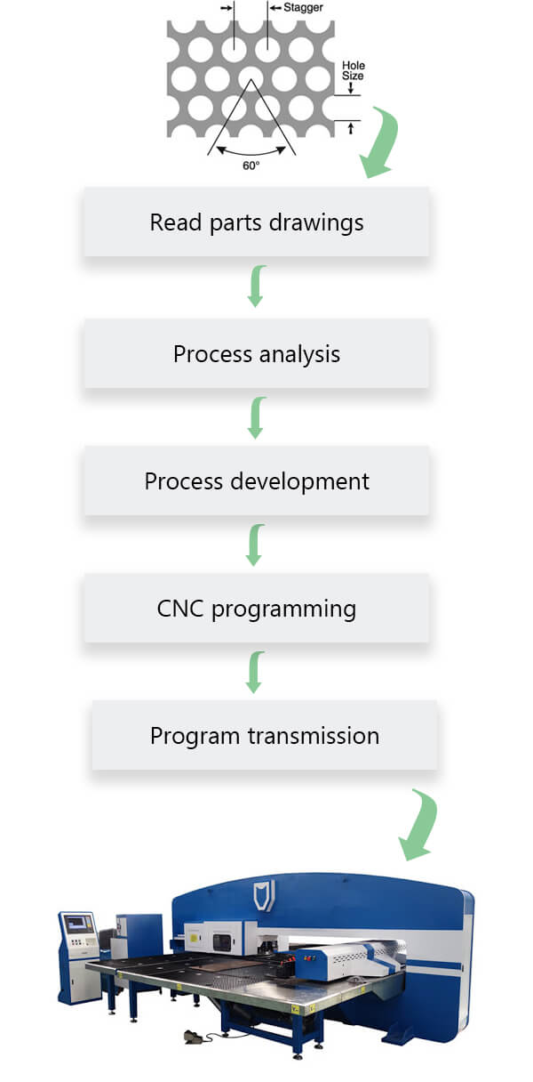
According to the original part drawings and process requirements, a CNC machining program for the part is compiled and input into the digital control system of the CNC turret punch press. This controls the relative movement of the tool and workpiece, allowing for the successful machining of the part.
1. Read parts drawings:
A comprehensive understanding of the technical specifications in the drawings is necessary, including dimensional accuracy, tolerances for shape and position, surface roughness, the material of the workpiece, hardness, machinability, and the number of components.
2. Process analysis:
Process analysis must be carried out in accordance with the specifications outlined in the drawings for the components. This includes analyzing the structural feasibility of the components, evaluating the material and design accuracy, and determining the approximate steps in the process.
3. Process development:
Based on the process analysis, all necessary information for processing must be developed, such as the process flow, requirements, tool trajectory, displacement, and auxiliary functions. This information should be documented on process cards and technique cards.
4. CNC programming:
Part programming should be performed based on the parts diagram and process details, following the instruction code and programming format specified by the utilized CNC system. This can be achieved through manual code editing or computer programming software.
5. Program transmission:
The written program is inputted into the CNC unit of the machine using a transmission interface. Once the machine has been set up and the program has been retrieved, the component can be machined to meet the specifications outlined in the drawings.
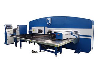
II. What Is CNC Turret Punch Press?
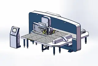
The Numerical Control Turret Punch Press (NCT), also known as a CNC Punching Machine, is a main category of CNC Punching Machines. NCT combines mechanical, electrical, hydraulic, and pneumatic elements and is used for punching and shallow drawing of plate materials through turret punching tooling.
The CNC turret punching machine is a versatile automatic machine that can handle frequent changes in products and processes, as it requires a variety of operations and steps. The relative positioning between the tool and workpiece is represented by numerical code.
The digital information is inputted into the computer through a control medium such as paper tape or disk, and the computer processes and executes the input information, issuing instructions to control the machine’s servo system or other components, allowing the machine to automatically produce the desired parts or products.
III. Turret Punch Press Working Principle
In the absence of any alarms on the machine, the CNC machine executes a program as instructed. The X and Y axes move the steel plate to the punch location, and the T disk positions the required mold at the punch head. The hydraulic punch head then performs a stamping on the mold.
This process is repeated, with the X and Y axes moving to a new position after each stamping, until the entire program has been executed. Finally, the machine returns to the feeding position.
IV. Types of Turret Punch Press
Since Wiedemann invented R2 manual multi-station punch in 1932, the numerical control turret punch (NCT) has been widely used in the field of sheet metal processing and has been developing in structure and performance.
For example, the early CNC turret punch had no automatic programming software and could only be programmed manually on the CNC system.
However, the current CNC turret punch is basically equipped with automatic programming software, and its work efficiency and processing ability of complex parts have been greatly improved than before.
In terms of ownership, there are more than 20000 sets of CNC presses in the United States and nearly 20000 sets in Japan.
China has developed rapidly in recent years, with a conservative estimate of about 6000 sets.
In terms of the development situation of the sheet metal industry, there should be a lot of room for development.
However, the personnel engaged in the sheet metal industry sometimes do not know very well about the performance and structure of various CNC presses, let me briefly introduce all kinds of CNC turret punches.
According to the working principle of driving striking head, CNC turret punch can be divided into three categories:
1. Mechanically driven CNC turret punch
This is the earliest type of CNC turret punch machine tool, which is still produced and used by some manufacturers.
Typical representatives include Muratec’s C series, Amada’s Aries series, PEGA series, COMA series, etc.
This kind of CNC turret punch drives the flywheel to rotate through the main motor, uses the inertia of the flywheel for stamping, and is controlled by the clutch.
This kind of machine tool has the advantages of simple structure, low product price and stable performance.
But the disadvantages of this kind of machine tools are also obvious.
First of all, the mechanical CNC turret punch must wait for the flywheel to turn once before stamping.
The stamping stroke is fixed, so the stamping speed can not be improved.
At present, the maximum speed is only about 180 times/minute.
This is also the main reason why many manufacturers no longer produce such turret presses (Amada stopped producing Aries this year, which has already stopped production in Japan).
Secondly, because the stroke of the striking head can not be controlled, it is difficult to control when forming and stamping.
Such machine tools must adjust the number of punching dies to achieve ideal molding, which is difficult to adjust.
In addition, this kind of machine tool also has the disadvantages of large power consumption, large stamping noise and so on.
2. Hydraulic drive CNC turret punch
With the development of technology, hydraulic CNC turret punch has appeared.
This kind of machine tool has been widely used because of its many advantages.
Typical representatives of such machine tools include Muratec’s V series, Amada’s Vipros series, TRUMPF’s TC series, etc.
This kind of machine tool is driven by hydraulic cylinder and controlled by electro-hydraulic servo valve.
Therefore, the stamping speed has been improved by leaps and bounds. Up to 1000 times/min.
Secondly, because the stroke of the hydraulic cylinder can be controlled, the forming die can be adjusted by controlling the stroke of the striking head, which is convenient to use.
When working, controlling the punching head to press the die can reduce the stamping noise.
In addition, through communication with manufacturers, we can process die processing including rolling rib, rolling cutting etc (mechanical press can’t).
Due to the above advantages, hydraulic turret punch has been widely used.
However, there are still many deficiencies in this kind of machine tools.
First, this kind of machine tools have high environmental requirements.
Too high or too low temperature will affect the normal operation of the machine tools.
If the temperature is too low (< 5 ℃), preheating is required before operation.
Secondly, the power consumption is large, which is the largest power consumption in all kinds of CNC turret punches. Generally, it is above 30KV.
In addition, the hydraulic oil should be replaced once a year, and the large floor area is its disadvantage.
3. CNC turret punch driven by servo motor
Due to the shortcomings of the above two types of turret punch presses, manufacturers have developed the third generation CNC turret punch.
This is the CNC turret punch directly driven by servo motor.
The typical representatives are M2044ez and M2048lt of Muratec company.
Due to the technology of directly driving the striking head by servo motor, the power consumption can be greatly reduced while maintaining high-speed stamping (up to more than 800 times/min).
This is because when the machine tool driven by the servo motor does not punch, the main motor is in a static state and does not consume power.
Compared with hydraulic machine tools, the power consumption of servo motor turret punch is about one-third of it.
Secondly, the CNC turret punch driven by servo motor, like the hydraulic CNC turret punch, the stamping stroke can be adjusted, so it is very convenient to adjust the forming die.
The rolling rib and rolling cutting die can be processed like the hydraulic punch, and the stamping noise can achieve the ideal effect.
The turret punch with servo motor has low environmental requirements.
It can be started immediately in spring, summer, autumn and winter without preheating.
Because there is no need for hydraulic device, there is no trouble of replacing hydraulic oil, and it is very environmentally friendly.
In addition, the machine tool has a compact structure and occupies a small floor area.
V. Structure of CNC Turret Presses
1. Main drive section
There are two main types of drive for CNC turret presses.
One is the mechanical main drive
The other is the hydraulic main drive.
Mechanical main drive principle (300 in ET-300 refers to a nominal force of 300KN)
The main motor drives the flywheel by means of a small pulley, which in turn drives the crankshaft by means of the clutch/brake engagement or separation.
It rotates and then drives the slider up and down through the crank connecting rod mechanism, and impacts the selected mold on the turntable for punching or other molding processes.
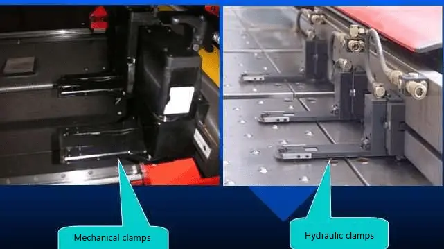
The clutches-brakes used in the mechanical main drive presses come in two main forms, one pneumatic friction clutch and the other hydraulic clutch.
Operating principle of hydraulic main drive turret press machine (300 in VT-300 refers to a nominal force of 300KN)
The principle of the hydraulic main drive is that the hydraulic oil supplied by the hydraulic system is fed into the fluid by the action of an electromagnetic reversing valve.
The upper and lower cavities of the cylinder make the piston rod drive the ram up and down in reciprocal motion, impacting the mold for punching.
In recent years, with the rapid development of hydraulic technology, more and more presses using the hydraulic main drive, due to the characteristics of hydraulic drive presses with constant pressure in the full range of stroke, more suitable for some special processing process needs, such as shallow drawing, knocking down holes and other forming processes.
2. Axis of motion
The CNC turret punch has four axes of motion: X, Y, T and C.
X, Y-axis are two linear axes
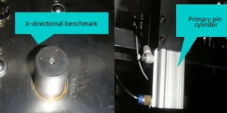
The X-direction is parallel to the direction of the two jaws and the Y direction is parallel to the direction of the locating pin or column. See the figure below.
The clamping of the jaws moves the steel plate back and forth to the point where it needs to be stamped.
The T-axis is the turret press tool bank.
It is mainly used for the storage and recall of dies, and when the tool selection program is performed, the corresponding dies are transferred under the punch.
The number of turret press dies can be divided into 20, 24, 32, 40, etc. depending on the machine model.
C-axis control for rotatable stations
Usually configured in two stations, the tool can be used in a wider range of applications, it can be freely rotated from 0-359.999 and can process more complex shapes.
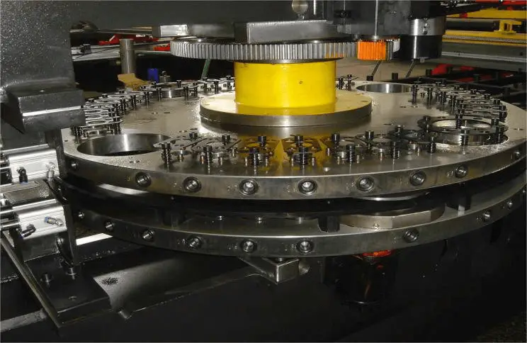
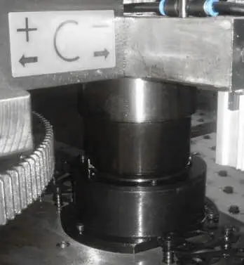
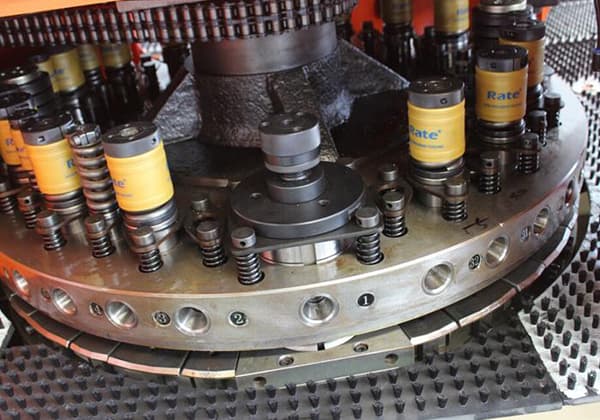
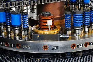
3. Turntable
The turntable, also known as the rotary head, turret, is a CNC turret press used to store the mold, equivalent to the tool magazine on the machining center.
There are two turntables for CNC turret punching machines, called upper turntable and lower turntable.
Currently, the normal number of workstations is: 32.
The upper turntable is used to install the guide sleeve of the upper die, the die support spring, the upper die assembly.
The lower turntable is used to mount the lower die holder, die press, lower die, center support, etc.
1) Distribution of dies on the turntable of a CNC turret punch
Single-row distribution, double-row distribution, triple-row distribution are commonly seen.
An excessive number of distributed rows can easily cause force bias in the punch.
Generally speaking, when three rows are distributed, the punch is often made of a movable type, i.e., the punch needs to punch one row of dies, and the punch is moved over the corresponding row of dies by a moving device.
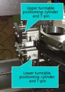
In order to make the upper and lower turntable accurate positioning, the outer circumference or end surface of the upper and lower turntable are equipped with tapered positioning holes, when transferred to the corresponding die position, the positioning cone pin can be inserted to ensure accurate positioning.
The axis that drives the turntable is usually called the T-axis.
The T-axis drive consists of a servo motor, gearbox, sprocket chain (timing belt), positioning cone pin, positioning cylinder (positioning cylinder), upper and lower turntable.
When the CNC system signals the need to use a certain die, the positioning cone pin is automatically pulled out, the servo motor rotates, and after deceleration drives the turntable to rotate, when the die is turned directly below the punch, stop the rotation, the cone pin is inserted into the corresponding cone pinhole, so that the upper and lower turntable is accurately positioned.
2) Criteria for determining the concentricity of the upper and lower molds to be corrected
When a new mold is installed or an already ground mold is installed, first make sure the clearance of the mold matches the plate.
If the workpiece is machined and the punching burrs are found to be large after only a few punches, remove the mold to observe the wear of the mold.
It can be judged from the edges that the concentricity needs to be corrected if the edges are partially rounded or white as if frost has fallen, especially the diagonal of the edge.
3) Synchronization correction after an error on the upper and lower turntable
The upper and lower turntables are driven by a digital AC servo motor, which is coupled to the input of the gearbox via a flexible coupling, and the output of the gearbox is driven up and down the turntable via a chain and gear.
The adjusted chain should have a drop of 6-13 mm.
If the upper and lower turntable positions are misaligned due to clips, etc., a synchronous adjustment must be made according to the following steps.
Loosen up on the lower or upper turntable
Turn the lower turntable T1 under the strike head manually
Several times in and out
Fine-tune the upper and lower dials until the turntable wobbles minimally after the pin is in
In the case of a pin in, tightening the lower or upper turntable is sufficient.
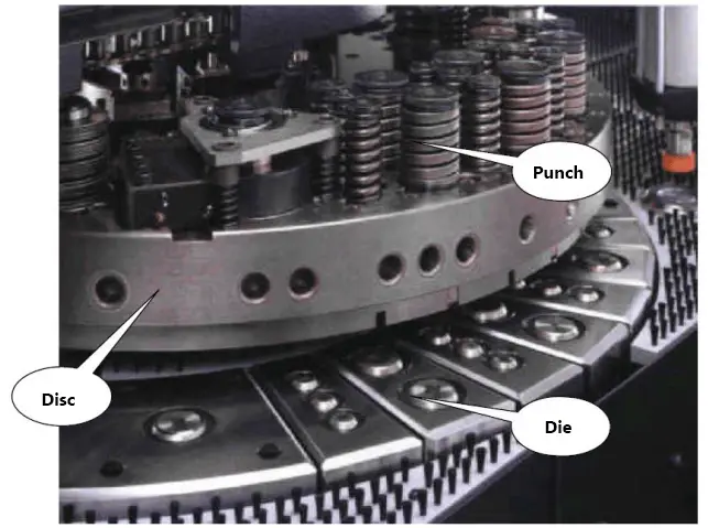
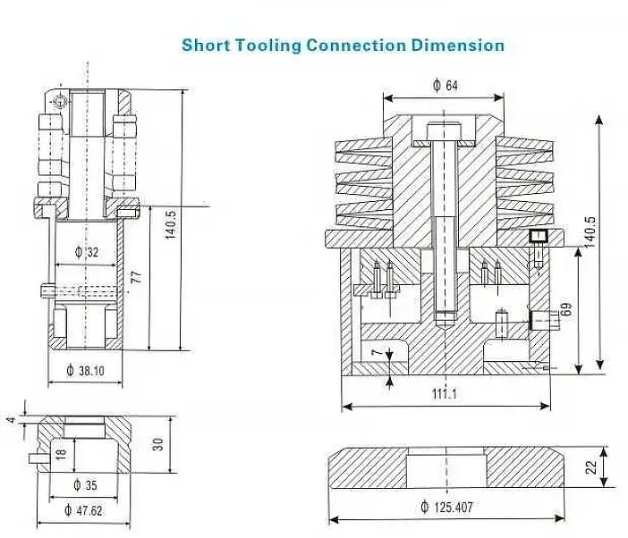
Molds are the main tools used to process sheet material.
At present, the more common CNC turret punching machine dies have two kinds: long structure dies and short structure dies.
Generally determined by the material and material thickness.
These two structures of the mold both need to be installed on the upper turntable support spring, so that the mold can be reset in time after the punch.
In China, the die material on the CNC punching machine is usually Cr12MoV and LD.
The dies with Cr12MoV material are more suitable for medium carbon steel sheet processing, while the dies with LD material are more suitable for difficult stainless steel sheet processing.
The life of the molds using these two materials is generally 200,000 to 300,000 times.
2) Precautions for the selection of molds
(I) Selection of standard molds
(1) The cutting edge diameter of the mold should be as much as possible greater than two times the thickness of the processing plate, the diameter should generally be greater than 3 mm, otherwise it is easy to break, and the life is very short.
However, it is not absolute, it is recommended to use imported HSS as mold material below 3mm diameter.
(2) If the die size of the plate is close to the limit size of the workstation, please use a larger workstation to ensure that there is sufficient discharge force.
(3) All sharp corners should be replaced by rounded corners, otherwise they are prone to wear or collapse.
In general, it is recommended to use a corner radius of R > 0.25t instead of clear corners whenever possible.
(4) When processing the plate for high Cr material (such as 1Cr13 and other stainless steel) and hot-rolled plate, due to the inherent characteristics of the plate is not suitable for the use of domestic high Cr mold, or it is very easy to wear, pulling and strip material and a series of disadvantages.
It is recommended to use imported high-speed tool steel as the mold material.
(II) Selection of molds for forming.
(1) Different CNC press slides have different strokes, so pay attention to the adjustment of the closing height of the forming mold.
In order to ensure adequate forming, it is recommended to use an adjustable striking head.
Adjustments should be made carefully, and each adjustment should not exceed 0.10mm, otherwise the mold will be damaged or even damage the machine.
(2) Forming should be as shallow as possible, generally speaking, the total height of forming is not more than 8mm, the reason for this height so it takes a long time to unload the material.
The forming process must be used at low speed, preferably with a delay time.
(3) Workstations near the forming tool station is not available because the height of the forming tool is much higher than that of a normal mold.
It is best to put the forming process at the end of the program and remove it after the punch.
(4) For stretch forming molds, use a lightweight spring assembly to prevent tearing or uneven deformation of the sheet and difficulty in discharging the material.
(5) If the two shapes are close together (front, back, left and right), please be sure to explain it to us, otherwise there may be interference.
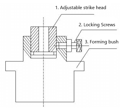
(6) The mold adjustment method is shown in the following figure.
(7) After the molding mold is installed, loosen part 2, turn part 1 clockwise, rotate to the lowest point, then tighten part 2.
(8) First empty punch, such as no abnormalities, the sheet material into the punch, measure the height of the molding, if the height is not enough to loosen piece 2, piece 1 counterclockwise rotation (rotation of a circle is generally 2mm, depending on the size of the thread distance, please adjust appropriately to avoid damage to the mold), and then tighten the piece 2, constantly adjust, test punch, until reaching the required height.
3) Assembly and maintenance of molds
Sharpening of the mold
Regular sharpening of the mold can not only improve the service life of the mold, but also improve the service life of the machine, so it is important to master the correct and reasonable sharpening time.
The straightforward way for the user to determine whether a die needs sharpening is.
After a certain number of punching, check whether the punching quality has a large burr, then check whether the upper die edge rounded (rounded ≥ R0.1), whether the gloss disappears.
If this happens, it means the punch has been dull, this time needs to sharpen.
The service life of mold can be increased 3 times if sharpened at the right time, but incorrect sharpening can rapidly increase the destruction of the mold edge and reduce its service life.
The grinding feed should not exceed 0.015mm each time when sharpening, too much grinding will cause overheating and burning of the mold surface, which is equivalent to the annealing treatment, and the mold will become soft, which will greatly reduce the service life of the mold.
The surface of the grinding wheel should be cleaned. It is recommended to use medium-soft 46-grain grinding wheel.
The amount of die sharpening is a certain amount, the normal amount is 4mm, if this value is reached the punch will be scrapped, if continued use, it will easily cause damage to the die and machine.
The final sharpening should be performed by professionally trained personnel.
Note: Demagnetize in time after sharpening, and adjust the height of the mold as before sharpening.
The service life of the mold
For the user, increasing the service life of the tool can significantly reduce the cost of use.
There are several reasons that affect the service life of a mold.
Whether the material of the mold has been specially treated.
The structural form of the mold.
Gaps in the lower mold.
The position accuracy of the upper and lower molds.
Adjust the rational use of the gasket.
Whether the stamped plates are well lubricated.
Whether the pressed sheet is flat.
Type and thickness of pressed plates.
The neutrality of the upper and lower stations of each turret of the stamping machine.
The guide key on the machine turret is intact.
The most direct of these factors is that the thicker the plate, the harder the material and the use of the step punching process, the shorter the tool life.
Also, wipe down the area around the die before putting it into the die.
After cleaning, spray some oil on the die and insert it into the die, and the concave die can also be inserted into the die.
Special attention should be paid here to the consistency of the orientation of the upper and lower molds.
Carefully check that the upper and lower molds are of the same size before installation, and that the edges are in the same direction.
If misplaced, it can break the mold and even damage the machine.
After the molds are installed, let the turret rotate, while observing the upper and lower turret, especially the concave mold has no uneven height.
If there are uneven height, the cause should be carefully checked.
Molds that are not normally used should be regularly protected against rust and oiled.
After using the mold, clean the mold, place it neatly, wrap it with a protective film, put it into the mold box, and put it in a fixed position to prevent the mold from being bumped, burr, or falling into the dust, rust and affect the next use.
Lower die gap
The clearance of the lower die is determined according to the thickness of the processed plate.
For example, the lower die for 2mm plate cannot be processed for 3mm plate, nor for 1mm plate, otherwise it will increase the wear and even break the die.
When the die spring is skewed or shortened, it should be replaced in time.
The die amount during stamping should be controlled between 1 and 2mm.
The closing height of the mold is adjusted according to the drawing requirements.
Forming mold should also pay attention to the direction of the keyway
The test punch is carried out strictly in accordance with the above-mentioned adjustment steps, and with reference to the requirements on the user’s mold order, such as the height of the stretch, whether to pre-punch holes, etc., otherwise the mold will be damaged or do not meet the user’s requirements.
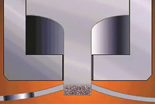
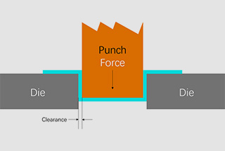
The gap between the convex and concave dies expressed as the total difference.
For example, when using a cam die of 10 and a concave die of 10.3, 10.3-10=0.3 (hole diameter of the concave die – hole diameter of the cam die = clearance), the clearance is 0.3mm.
By clearance, we mean total clearance on both sides, which is one of the most important factors in punching.
If the gap is not selected properly, it will shorten the life of the mold, or burrs, causing secondary shearing, making the shape of the cut irregular, the release force increases, so the correct selection of the gap value is very important.
For the machining of soft steel, the gap should be 20-25% of the thickness of the material.
When machining aluminum, the gap should be 15-20% of the thickness of the material.
When machining stainless steel, the gap should be 25-30% of the thickness of the material.
For example:
For mild steel with a thickness of 1.2mm, the gap is calculated as follows:
1.2mm×0.2=0.24mm, 1.2mm×0.25=0.3mm, so the recommended clearance is 0.24mm~0.3mm.
According to the current market of CNC punching machine tool production plant gap ratio selection statistics, combined with the actual situation of state-owned machine tool precision, my company recommends the following “recommended gap under the die”.
For special cases, it needs to be designed according to user requirements.
Sheet Thickness mm
Types of materials
Mild steel
Aluminum
Stainless steel
0.8~1.6
0.2~0.3
0.2~0.3
0.2~0.35
1.6~2.3
0.3~0.4
0.3~0.4
0.4~0.5
2.3~3.2
0.4~0.6
0.4~0.5
0.5~0.7
3.2~4.5
0.6~0.9
0.5~0.7
0.7~1.2
4.5~6
0.9~1.2
0.7~0.9
Note: Our recommended lower die clearance is used to ensure the life of the die and is not very strict.
It should be precisely formulated according to the actual situation and in conjunction with the needs of the user.
5) Points to note during processing
Maximum hole diameter and tonnage of the punch
For example:
Whether the plate with a thickness of 6mm, and diameter Ф88.9mm can be cut or not, it can not be estimated by imagination.
It is determined by the punching capacity.
The pressure required for general punching is determined by the following formula.
P=A × t × σc
P-punch force(kg)
A-Perimeter of the perforated hole(mm)
t-plate thickness(mm)
σc-Material shear strength(kg/mm)
Such as VT-300 punching machine for pressing 6mm hot-rolled plate, the maximum processing hole diameter is:
30×1000=3.14×D×6×42
D=Ф37.9(mm)
Therefore, if punch the hole on the 6mm plate by the cnc punching machine, the maximum diameter that can be get is Ф37.9mm.
Beyond this value, other methods should be used, such as the small circle die-step punching method.
Oil lubrication
The amount and number of oil injections depend on the conditions of the material being processed.
For a rust-free, non-scaling material, oil the mold with light machine oil.
Material with rust and scale, rust gets between the mold and the jacket during processing, like the deed, and prevents the cam from moving freely.
In this case, if oiled, it will make the rust more easily stained, so when punching this material, instead, wipe the oil clean, break down the mold every half month, wash it with gasoline and reassemble it, so that it can be satisfactorily processed.
High-speed CNC punching machine molds must be strictly maintained, and the unloading sleeve, the oil injection port, the core of the mold and the contact surface of the unloading sleeve and the concave mold are lubricated with light oil on a regular basis, so as to extend the service life of the mold.
But too much lubricating oil often stays in the upper die end surface, the strike during punching and cutting is easy to make the upper die end surface and waste to produce vacuum adsorption between the formation of slag, ie: waste rebound.
In this case, the sheet should be cleaned of any grease scale and the mold should be kept clean and not overfilled with lubricant for a smooth punch.
Carry-over on the head punch and scrap rebound
Carry-over on the head punch and adhesion means that under normal conditions, the upper die core and sheet material can not be disconnected in time or completely.
The hazards of carry-over on the head punch.
(1) Will damage or break the die core.
(2) It can damage the clamps and damage the sheet product, and the curled sheet can even hit the shroud.
(3) Mould guide sleeve and core sliding resistance is large.
(4) The required discharge force is greater than the spring force.
(5) The feeding speed is too fast and the spring is not responsive or sensitive.
(6) Material accumulation psoriasis.
(7) Waste rebound.
(8) Other reasons such as mold clearance and accuracy.
The solution
(1) According to the samples and other test data, the springs have a life expectancy of 500,000 cycles, sometimes even shorter under harsh conditions, at which point the springs will fatigue and lose their proper elasticity, the springs will shorten significantly or even break, and new springs must be ordered from a trusted die supplier in time.
(2) The inductance should be controlled between 1-2mm, too deep will cause the core’s release stroke and resistance to increase, thus prolonging the spring’s reaction time.
The core is not completely out of the sheet material before feeding, may damage the mold, plate or clamp, etc.
(3) When there is too much dust and other dirt on the sliding surface or lack of oil, the sliding resistance will be increased, counteracting some of the spring force, which may cause a carry-over of material.
At this point, the mold should be disassembled, lubricated and improve the lubrication conditions.
(4) The pushing force is greater than the spring force mainly refers to the punching tonnage, there are several possibilities:
One is that the cutting edge is severely dulled, requiring additional tonnage, and the cutting surface is rough and burrs increase, producing a great resistance. This should be sharpened in time.
The second is that the gap between the mold and the plate does not match, when the gap between the mold and the plate is small, it will make the material hold the convex mold.
In this case, you should choose the lower die that matches the plate or grind the lower die to make the gap bigger.
Thirdly, when the mold size is close to the limit station size and the sheet is thick, the required discharge force is greater than the spring force.
In this case, it is necessary to jump up a station or use heavy-duty spring.
(5) When high Cr die material and high Cr stamping plate (such as 1Cr13 and other stainless steel) continuous punching, the temperature will rise and produce affinity.
Equivalent to a pair of the same friction payment, it is very easy to wear the edge or produce accumulation of scabbards.
Therefore, when punching stainless steel, it is recommended to use imported HSS instead of domestic high Cr material, such as Cr12MoV, etc.
In addition, when punching stainless steel with a film is often encountered, this film is thin and tough, and the plate is loosely attached to the separation phenomenon when punching and cutting is prone to carry-over material.
In this case, one should choose a sharp-edged imported high-speed steel mold, the second is to put the side with the film on the bottom, so that the film is located near the shear layer to achieve the purpose of being completely cut off.
However, this should be done with full consideration of the impact of the burr facing the part.
(6) The rebound of the waste is also one of the important reasons for the material carry-over.
After the rebound of waste material, if half of the waste in the lower mold, it will cause the phenomenon of punching double material, so that the mold serious bias and tonnage increase, which causes the material or mold damage.
(7) The last point is that the accuracy of the mold itself and the accuracy of the alignment of the machine position, may also cause the carry-over.
When this happens, you should use the regular professional CNC mold manufacturer to manufacture the mold and use the calibration bar to correct the machine’s mold position.
Waste bounce
Waste bounce refers to the phenomenon of punching waste not smoothly discharged from the hole in the die, but bounced to the end of the die or the surface of the part blank, this ejected waste is also known as pad slag.
Hazards of waste rebound
(1) When the die continues to punch near the slag, the discharge sleeve strikes the slag into the surface of the sheet, causing the part to be scrapped for failure in size and surface quality.
(2) The slag falls on the lower turntable, causing a hidden danger of feeding, and the plates can be scratched or even smashed.
(3) Sometimes the mold is damaged due to the continuous production of slag and the slag overlap exceeds the strength limit of the mold, and the scrap rate due to slag is significantly increased when the production of single pieces or small quantities is high.
(4) When half of the bedding slag is impacted at the bottom die opening, it will cause a carry-over of material.
Causes of waste bounce
(1) The reason for the mold itself
Reasonableness of the gap
The sharpness of the blade
Whether the mold is suitable for the mold
Whether lubrication is beneficial
(2) Causes of material condition
Whether the surface condition of the material is good or not
Is the direction of the material adhesion layer conducive to impact
(3) Reasons for programming
Mold selection
Punching and cutting sequence and direction
Determination of impact size
Solutions for the waste rebound
(1) The lower die gap will cause the waste to warp upward, reducing the contact area with the inner surface of the die and reducing the frictional resistance, which will cause the waste to bounce back in the state of high-speed punching.
So for the case of a too large gap, we must choose the appropriate gap, sometimes even consider using a smaller gap.
(2) After a certain number of sharpened die impacts, the edges of the cutting edge become white and rounded like frost, which is the result of hardening and passivation of the process.
In such a state, the processing will make it more and more evident that the scrap will be more and more tolerant to the edge of the die, and it is very likely that it will be brought out of the concave die with the return of the upper die.
In this case, the edge must be sharpened immediately and demagnetized with a demagnetizer after sharpening.
(3) Polyurethane nails for upper die edge diameter or width of 9mm or more
The width is less than 8mm, and the 2° beveled edge is used for long and large workpieces, which can effectively prevent the waste from rebounding.
However, the polyurethane resin is a wearable part, so users should check it weekly and replace it in time during use.
The bevel should be kept after sharpening, and should not be sharpened to a flat edge because of lack of equipment or fear of trouble.
(4) The input die amount should be controlled between 1-2mm, too shallow will cause the scrap not to be completely cut.
In this case, the amount of die sharpening is involved.
If the mold is sharpened more than 4 mm, it is necessary to consider changing the core of the mold, otherwise the convex mold will have less and less penetration into the concave mold.
At the same time, the energy applied to the sheet during impact increases, which causes the sheet to warp more, which increases the chance of rebounding.
(5) If the depth of the lower die edge is too high, it will cause the waste to overlap.
When the air between the scrap is compressed, the above scrap will be ejected from the lower die with the return stroke.
The standard depth of the lower die should be the sum of the inductance, material thickness and sharpening volume.
(6) When the upper and lower molds or the upper and lower molds are heavily eccentric, excessive burrs on one side can also cause the waste to be carried out of the lower mold with the movement of the sheet.
(7) It is inevitable that there is a little bit of lubricant or anti-rust oil on the bottom of the upper mold or sheet, but never so much as to form a fluid.
When impacted, it is easy to cause vacuum adsorption between the upper die end surface and the waste, forming a waste rebound.
In this case, wipe off the oil from the upper mold or plate.
(8) The adherent layer of the sheet is also an important factor in the rebound of the waste.
As with material carry-over, a sharp-edged mold should be used and the adherent layer should be placed underneath.
(9) A very important reason why the high-speed CNC punch is becoming more and more widely used is its flexible processing characteristics of splicing and punching.
That said, don’t be frugal about choosing molds when programming.
For the characteristics of a certain hole, first select the mold that can complete the hole in one go, and when it is necessary to cut, the smallest cut waste, the largest, closest to the mold size should be selected.
If the minimum scrap is too small, the scrap is not easy to be punched off when the mold gap is large.
Even if the waste is punched into the die, if stranded on top of the previous waste, it is easy to bounce out of the die due to vibration, the formation of waste bounce, so it must be scientifically selected mold.
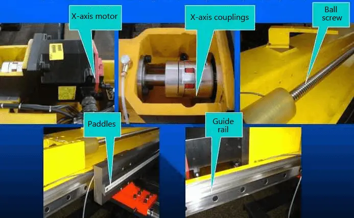
5. Feed parts
The feeding components of a CNC turret press usually include the crossmember, Y-axis drive, jaws, table to support the sheet, etc.
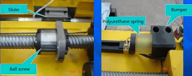
1) The crossbeam is generally a welded structure, on top of which are fitted ball screws, linear guides and couplings, servo motors, the two sides of the support is fixed on its lower surface, guided by linear rolling guides.
In order to ensure a smooth and high-speed movement of the carriage and guide, the end face of the carriage is equipped with a dustproofing device and the machine must be kept in a clean working environment to prevent dust from remaining in the grooves of the guide and screw and causing sharp wear.
The Y-axis is driven by an AC servo motor, which is directly connected to the ball screw via a backlash-free flexible coupling, which is pre-tensioned during assembly to ensure backlash-free transmission.
Note: The nut on the screw has been adjusted before the machine leaves the factory and the user is not allowed to adjust or disassemble any part of this part during use.
2) The drag plate is an annealed cast iron member and is guided by a guide rail fixed to the crossbar.
As with the Y-axis rails, the preload adjustment of the screw nuts is made at the time of the machine’s factory adjustment assembly and must not be adjusted by the user during use.
The ends of the X and Y-axis screws are fitted with polyurethane bumper blocks to prevent damage to the screw and other parts of the screw due to various misuse.
The lubrication nozzle in the bearing housing is used to lubricate the screw support bearing at regular intervals, with a lubrication cycle of once a week.
When working, the clamp is installed on the X-axis direction of the drag plate, and through the rotation of the servo motor, the ball screw is driven by the coupling, which drives the drag plate to move back and forth along the X-axis direction on the linear guide, thus achieving the purpose of feeding material.
3) At present, the X-axis stroke is 1250mm, 1500mm, 2000mm, 2500mm.
If repositioned, the X-directional processing size will be larger.
The Y-axis drive is basically the same as the X-axis, but also consists of ball screws, linear guides and couplings, servo motors.
When the Y-axis drive is working, it is connected to the crossmember by a joint seat, which drives the crossmember along the Y direction.
Due to the limited depth of the throat, the common strokes in the Y-axis are 1250mm, 1500mm.
In order to prevent damage to the cross material and the table due to impact when the machine is out of control due to control malfunction or mishandling, buffer devices are installed at both ends of the X and Y direction screw strokes
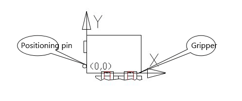
A gripper is a manipulator used to hold sheet material, usually powered by compressed air or hydraulic oil. The gripper is generally connected to the drag plate on the crossbar via a T-slot or dovetail slot.
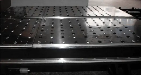
There are usually two types of table structures for supporting sheet materials: one is a fixed table and the other is a movable table.
The fixed table means that all the tables are not in motion during operation.
The biggest advantage of this structure is that the inertia of the feed is small and can be driven by a servomotor with low torque.
The movable table refers to the feeding table that moves with the sheet during the work.
The advantage of using this kind of table is that it has a small footprint, but the inertia of motion is large, and it needs to use a servo motor with high torque to drive.
In addition, there are two types of sheet supports on the table, one is a universal transfer ball (steel ball) and the other is a hard brush.
When using the hard brush table, the load capacity is smaller than the steel ball, high resistance to movement, but the noise is small, not easy to scratch the plate, more suitable for thin plate and fixed table use, the plate thickness is less than 3mm.
A mix of steel ball and brush is used for both.
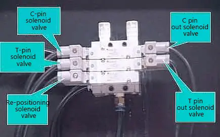
6. Airway system
The airway system of the machine consists of various directional control valves and air source triplexes.
The air supply connection is located on the front of the machine, and the required air supply pressure is 0.55Mpa or more, below the critical lower limit of 0.4Mpa, the alarm will stop working.
The air-using parts are: rotary die bonding mechanism, rotary positioning pin, repositioning, clamps, positioning block.
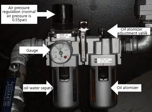
The pressure relay determines whether the pressure of the air source has reached the set value, if not, the CNC system will alarm.
Before the compressed air enters the actuator, the oil is brought to the pneumatic actuator through an oil atomizer for lubrication purposes.
The stability of air pressure is one of the prerequisites for machine work, and unstable or insufficient pressure can cause various problems.
Generally, there is a regulator at the air inlet, adjust the pressure, dial out the adjustment handle, turn clockwise to the specified pressure, press the adjustment handle.
If the pressure is lowered, the air pressure must be brought back to zero, the adjusting handle must be dialed out and adjusted counterclockwise until the rotation does not move.
Turn on the air source, at which point the pressure gauge indication should be 0.
Turn the adjustment handle clockwise to the specified pressure and press the adjustment handle.
If, after a period of operation of the machine, there is a chronic shortage of air pressure and the above methods are not effective, the following two options may be considered:
Air compressor replacement or repair
Raise the lower limit of the air compressor, or lower the critical value of the air alarm, by turning a small steel screw in the direction of “-” on the lower part of the pressure gauge, at this time you can see the green needle follows the corresponding movement.
Until the red light goes out and the air pressure alarm is eliminated.
This method must ensure that each pneumatic component is in order.
Lubrication of air ducts
It is done through the oil misters, the oil supply is adjustable.
By turning the adjustment screw counterclockwise, the oil supply to the oil misters increases, and by turning the adjustment screw clockwise, the oil supply to the oil misters decreases.
The size of the oil atomizer is proportional to the actual operating gas flow rate, the minimum airflow rate to start the oil atomizer automatic lubrication is 10L/MIN.
(1) The speed can be adjusted through the one-way throttle valve, and the compressed air from the air source enters the cylinder directly when it returns to its original position.
(2) The positioning pin of the turntable is connected to the pin by two cylinders through the coupling plate, the cylinder is supported on the fixed seat, the pin is controlled by two five-way solenoid valve, the speed is adjusted by a one-way throttle valve when positioning.
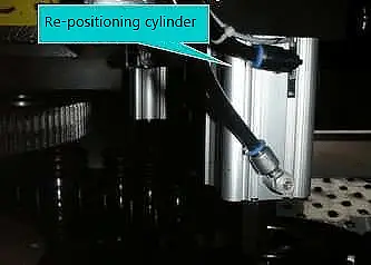
(3) The repositioning cylinder is controlled by two five-way solenoid valves, and the cylinder is fixed on the bracket connected with the bed.
The function of repositioning is to press the steel plate tightly on the table when the machine is repositioned, and to ensure that the steel plate is fixed when the clamp moves automatically.
When the length of the plate in the X-axis direction exceeds the X-axis stroke, the excess must be repositioned to complete the punch.
This feature extends the machine’s range in the X-axis direction (repositioning can only be done in the X-axis).
(4) The clamp cylinder is controlled by a two-position three-way solenoid valve, and the two-position three-way closure is controlled by a footswitch.
In the absence of a steel plate in the jaws, avoid empty clamping to prevent damage to the tooth plate.
When not ventilated, the spring causes the cylinder rod to retract and the jaws to open by its own weight.
The clamp is controlled by a footswitch or a button on the control board.
The maximum clamping thickness of the jaws is 6.35 mm.
The safety zone detection plate on the clamp is to detect the position of the clamp to protect the clamp from entering the danger zone during the working process, so as not to break.
(5) X-axis positioning home pin
The positioning block is directly connected to the cylinder rod, and the lifting of the positioning block can be controlled by manually controlling the operation button on the crossmember shroud during loading.
The origin pin is located to the left of the feed table and is used to determine the reference point of the X-axis.
The theoretical distance from the positioning surface of the origin pin to the center of the punch is 1250 (2500) mm.
When feeding, the cylinder lifts the pin (the jaw is open), the steel plate is close to the positioning surface of the jaw and the positioning surface of the pin, thus determining the original position of the steel plate on the table.
When the clamp clamps the steel plate, the steel plate is well-positioned, then the cylinder drives the origin pin down.
The origin pin is in its original position (i.e., dropped) throughout the job.
If for some reason the home pin does not fall or lift during operation, neither the X nor Y-axis can be moved and can only be restarted after the home pin has fallen.
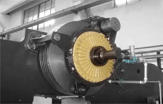
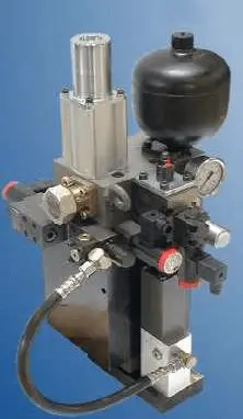
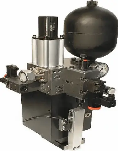
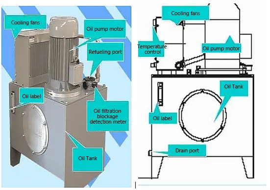
7. Hydraulic system(H+L)
The punch is mainly used to strike the die, it is the source of power for the punch and its own power is done by the hydraulic station.
Hydraulic stations are usually equipped with one main motor, one high-pressure pump and one cooling pump each, with air cooling.
When the oil temperature exceeds 40 degrees, it starts automatically, causing the oil temperature to drop.
The role of the hydraulic station is to provide a constant source of oil pressure to the punch.
Recommended hydraulic fluid model number: Mobil DTE-25 VG46 anti-wear hydraulic oi:.
The amount of oil used was:
Harley Economy (VT-300): 180 litres
Harley Premium (RT-300): 250 litres
The punching head can automatically select the punching stroke according to the thickness of the plate and realize the pre-pressing function, which can reduce the punching stroke and increase the punching speed.
Pictures of Hydraulic Punch Head
Hydraulic station pictures
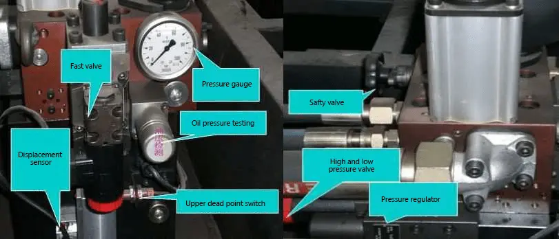
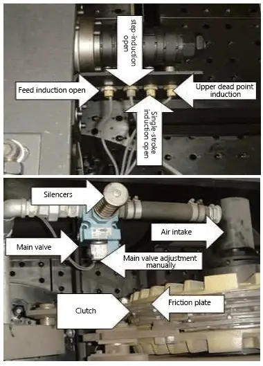
8. Mechanical clutches
The function of each switch in the upper dead point section and its adjustment method.
(1) Due to air pressure causes the dead point is not in place, in a manual way, start the motor, turntable pin into, press the dead point adjustment key F1, until the alarm disappears
(2) when the implementation of the program, there is an alarm, the machine tool is in a state of maintenance, in the case of not pressing the reset button, directly switch to manual mode, press the dead point adjustment key F1, until the alarm disappears; and then switch to automatic mode, press the cycle start, the machine will then interrupt the implementation of the program.
(3) If the machine is in a power-off state, the punch is not on the dead point, and just stopped in the rotating position, the upper and lower modes are not at the same angle, it is impossible to achieve the adjustment of the start-up state, it is necessary to adjust manually.
The step is, first confirm whether the air pressure is stable or not, then observe that there is a button on the clutch main valve that can be manually controlled.
Observe the direction of rotation of the upper dead center cam, and be sure to hold down the main valve button.
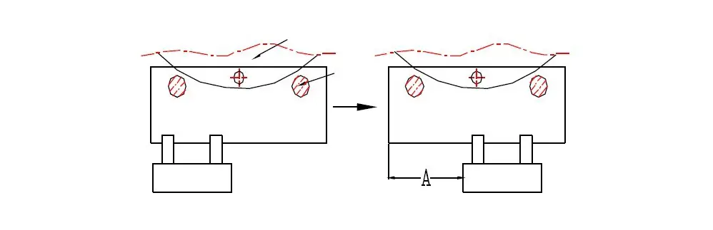
VI. Processing Range
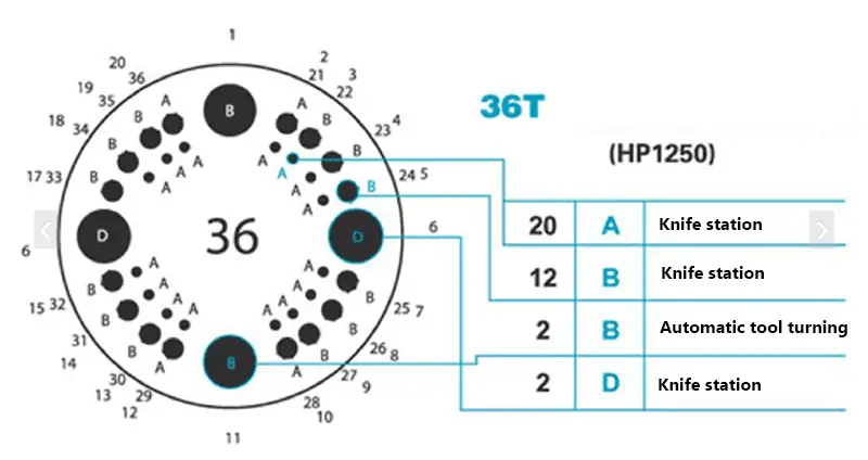
Let’s take the model HP1250 for example, which has a machining range of 1250*2500 (mm).
If the X direction is beyond this range, it can be adjusted using the automatic gripper command G27, in the form of G27X movement amount.
The diagram below shows the before and after situation when using the automatic jaws removal method.
The cross-sectional line shows two cylindrical plates that are used to hold the material in place when the jaws are loosened so that it does not move.
After the jaws are released, the jaws move outwards, and move in the X-axis in the positive direction of Amm, and then move inwards to the corresponding position, clamping, thus completing the entire movement of the jaws.
The range of work before and after the jaws is expanded as shown in the figure below.
If it’s in the Y direction beyond this range, there may be danger. This means that the jaws may be in a danger zone.
The situation in the danger zone is shown in the diagram:
In the first case, the jaws are located between the upper and lower moulds and the punch will damage the jaws;
In the second case, although the jaws will not be damaged, the material will be deformed because it is in a different plane.
The solution is to change the position of the jaws, change the tool position, change the size of the mold or design a substitute jaw.
VII. The Positioning of the Workpiece
The workpiece is positioned on the CNC turret punch by means of the jaws and Y-directional locating pins or square locating blocks, which are placed on the jaws to determine the Y-directional position, and on the locating pins or square locating blocks to determine the X-directional position.
Data on jaws
The two jaws of the CNC turret punch can be adjusted in the X-direction relative to each other to accommodate different plate sizes, but the two jaws cannot be infinitely close together, there is a minimum distance between them, see figure below. If the workpiece is smaller than the minimum, only one jaw grip can be considered.
Table of values for each knife gripper hazard zone and molding interference zone
When the jaws are holding the workpiece in motion, they may be washed out and damaged, so a safe distance must be left between the machined part and the jaw.
Minimum distance from the jaw in the Y direction = upper die radius + jaw width + deformation zone
Knife Type
Die dia. mm
Punch dia. mm
The minimum distance from the jaw in the Y direction mm
Type A
18
25.4
30
Type B
38
47.8
40
Type C
74
89
50
Type D
110
125.4
80
Type E
133
158
95
Note:
1) The material deformation area is usually 5mm, the specific value is determined by the material thickness and forming height, this value is for reference only.
2) Take 10 mm of jaw width.
Upward molding processing interference zone = upward molding radius + deformation zone
(Note: Deformation zone = radius or width of upward shaped element/2 + material deformation zone )
Type A
Type B
Type C
Type D
Type E
Min processing interference area
mm
12.7 + deformation zone
24 + deformation zone
35 + deformation zone
55 + deformation zone
67 + deformation zone
Interference zone for downward molding = radius of downward molding + deformation zone
(Note: Deformation zone = radius or width of downward shaping element/2 + material deformation zone )
Type A
Type B
Type C
Type D
Type E
Min processing interference area
mm
12.7 + deformation zone
24 + deformation zone
45 + deformation zone
63 + deformation zone
79 + deformation zone
VIII. Estimated Machining Time for CNC Turret Punch
1. Time to change the knife
Tool change time of approximately 1.5 seconds for adjacent tool positions.
An interval tool position change time of approximately 2.0 seconds.
Rotation time of approximately 2.5 seconds for tool change.
The above knife change times can probably all be uniformed to 2.0 seconds.
Even with an extremely complex workpiece with 30 knives, the changeover time should not exceed 15 seconds.
2. Number of punching holes
The maximum number of punches per second for a single hole knife is 8, with a hole distance of 4-5 mm, i.e. 480 punches per minute;
However, according to the condition of the tool and equipment, the number of punches per second is 4, i.e. 240 per minute;
The maximum number of punching times for multi-punching knives is 2 per second, i.e. 120 per minute;
However, depending on the condition of the tool and equipment, the normal punching rate is 60-70 per minute;
3. Forming time
Shaping time for a salad knife (including pre-holes) is about 1.3 seconds;
Forming time for a letter mold is about 0.7 seconds;
The forming time for a normal bale is about 3 seconds; for a taller bale it is about 4 seconds;
Due to the special molding conditions, it takes about 5 seconds to complete;
Bump approx. 1 sec.
Perforate for about 2 seconds.
About 2.5 seconds for the middle bridge.
Embossing about 1 second.
Half-cut for about 2 seconds.
Special forming in about 1.5 seconds
Self-tapping in about 2 seconds.
The offset is about 3 seconds.
Reinforcement for about 1 second.
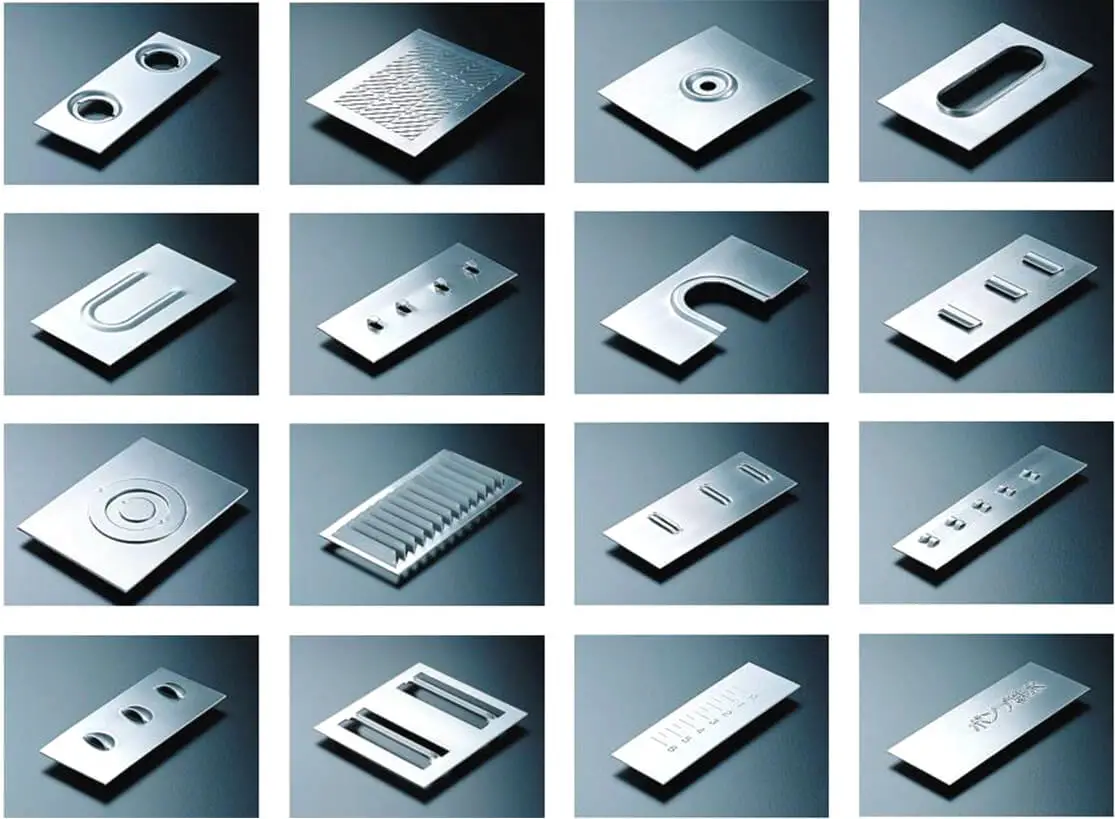
IX. Common Processing Methods
CNC turret punching can be done in various ways, such as punching mesh holes, segment punching, nibbling, cutting corners, automatic claw removal, etc.
Each machining method has a specific NC program instruction.
The use of the corresponding instructions not only makes the various types of machining easier but also less error-prone.
This section will explain some of these typical NCT machining methods.
1) Perforated hole
In practice, NCT often processes an alarming number of heat sinkholes.
The fastest processing speed is in G36 mode when punching mesh.
If more than 25% of the mesh in a unit area is punched, the material will be deformed and the process must be properly processed.
Usually, NCT stamps the whole sheet of material first, and then calibrates the workpiece after punching.
If there are very important dimensions that require accuracy, we will consider secondary processing after leveling.
If the size and distance of the holes are not the same, we will negotiate with the customer within the tolerance to change the size of the holes to the same, so that we can open the die for mass production (e.g., NCT multi-punching).
2)Continuous punch ( rectangular ) hole
In NCT processing, it is common to punch a large rectangular hole.
Punching such holes can be done in a small rectangular die with continuous punching.
3) Nibble
In the absence of a laser cutter, sometimes a larger ring or a straight circle is machined by nibbling.
4) Trim
5)Processing of salad holes
Due to the extruded shape of the salad hole, the material is deformed after stamping.
Salad hole filling range
Treatment with filler in the center position less than 10 mm from the edge.
If the edge is greater than 15mm, no filler is used.
If the distance from the edge is 10-15mm, the salad hole should be determined according to the actual condition of the salad hole to determine whether or not to replenish.
If the distance between two salad holes is greater than 5 mm, the two salad holes will not affect each other, and if the distance is less than 5 mm, the salad holes must be punched once to reduce deformation.
Salad hole filling method
The aim is to increase the processing speed and ensure the quality (reduce the number of joints).
A single salad hole filling with a large diameter as the base of both sides of the offset 5mm, this is the long side (assuming the length is A), then the other side for A/2+1 select SQA+1 square knife punch.
The two or more salad holes are filled together with a width of 10mm and length depending on the actual situation.
Pre-hole selection size for salad holes
In general, the following principles apply:
90°SaladΦpre=Φforming bottom hole+0.2&0.3
100°SaladΦPre=Φforming bottom hole+0.3&0.5
120°SaladΦPre=Φforming bottom hole+0.5&0.6
140°SaladΦ pre=Φ forming hole +0.7&0.8
The forming depth of NCT punching hole is generally not more than 85% (T<2.5mm).
6)Crimp line treatment
NCT crimping depth of 0.4T.
When using a 15*0.5 crimping tool, less than 20mm from the edge must be replaced.
When using 15*0.2 crimping tools, less than 15mm from the edge must be replaced.
The filling method is similar to the filling method of the salad hole.
The line is pressed either with a targeted line or with the entire bent line.
If one side of the bending line is pressed, the other side is not pressed, it is easy to bend, the size of one big, one small.
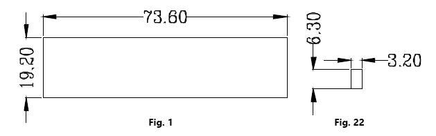
7) Die cutter
Reverse Die Cutter:
Figure 1 shows the notch size of the reverse die cutter and Figure 2 shows the die size of a word.
It can be seen that the reverse die cutter can hold up to 3 rows and up to 23 dies per row.
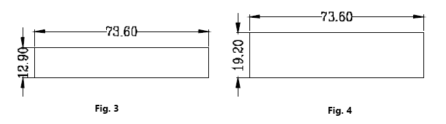
Front Die Cutter:
There are two types of notches for the front die cutter, as shown in Figure 3 and Figure 4.
The length direction is the same, but the width direction is different from the width of a die.
Therefore, in the operation, the corresponding treatment can be made according to the actual situation.
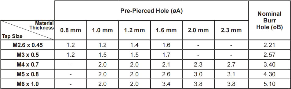
8) Perforate
Specialized knives are required for drilling holes.
The most commonly used aperture is the aperture used for the extraction of M3 buds (aperture ID 2.60.
The minimum distance from the edge of the NCT perforation is 3T and the minimum distance between two perforations is 6T.
The minimum safety distance from the bending edge (inside) is 3T + R, if small, the line must be pressed. (T indicates material thickness)
9) Tap the bottom hole
Since direct tapping can cause burrs to form, a small salad hole on the opposite side of the tapping hole can be punched to avoid this phenomenon.
The salad hole can also be used as a guide for tapping.
Salad holes are generally 0.3mm deep and 90-degree angle.
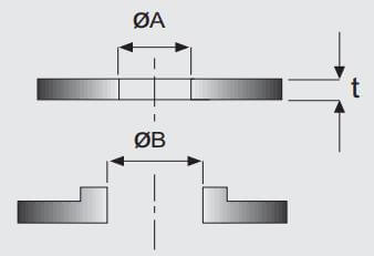
10)Draw or punching convex
There are two ways in which NCT can process the convex.
Development convex punching tool
With a normal tool, you can use the M command to draw or punch a convex, but only in the downward direction. As shown in the figure below:
The upper die of RO13 and the lower die of RO19 can be used to punch out the bumps. By the same token, it is possible to punch half shears and bumps.
Two points to note with this method: first, there must be upper and lower die available, and second, the forming depth must not exceed a material thickness.
11) Bead rolling
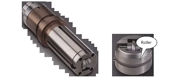
※Working principle of a roller cutting tool
When using a WILSON roller cutting tool to process the workpiece such as reinforcement, in essence, the upper and lower dies of the roller cutting tool are used to press the workpiece together, and then the gripper clamps the workpiece according to the shape of the processing element movement, so as to complete the process of processing such elements.
※ Roller cutting tool structure
The structure of the lower die:
The lower die of the roller cutting tools consists of the lower die seat and the roller wheel group (for the roller cutting tools of the lower die of the roller processing also includes the control wheel).
Roller wheel includes a bearing, you can rotate freely.
Now only to strengthen the rib roller cutter as an example of introducing the lower die of the cutting tool roller.
The die seat plays the role of supporting the roller wheel.
Upper die structure:
Rolling cutter composed of two parts which include the die seat and roller wheel group.
Now only to strengthen the tendon roller cutter as an example to introduce the upper die of the roller cutting tool, as shown in the following figure:
X. CNC Turret Punching Process
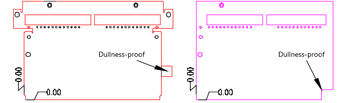
Dullness-proof treatment
For symmetrical or asymmetrical workpieces that are difficult to distinguish between left and right, anti-stalling measures are necessary to prevent the workpiece from being reversed during secondary machining on the NCT.
The following categories are commonly used.
1)Overcome by using the photoelectric induction installed by NCT itself.
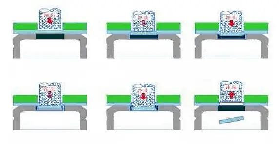
2) Use the way of adding material:
That is, on the opposite side of Y, according to the actual situation, add a small piece of material, the size is slightly smaller than the cutter used to cut this piece of material (usually SQ10-15), its position is roughly in front of the positioning pin or block, and then cut with a square knife.
As shown in the picture on the left below:
If, after the workpiece has been discharged from the NCT, other secondary processing is required to produce the shape, then an anti-still angle method can be used.
As shown above, on the right, the sluggish corner size is usually 10X10 to allow for a single punch out with the SQ10 square cutter.
Treatment where the distance between the hole and the edge is less than the thickness of the material
Punching a square hole causes the edge to be turned up, the larger the hole the more obvious the turning of the edge, in this case the LASER secondary cutting is often considered (the customer can also be consulted on whether this distortion is acceptable).
Note: The distance between the hole, the hole and the edge of the NCT punch should not be too small, its tolerance is as follows:
Material
Punch round hole
Punch square hole
Hard Steel (H-Copper)
0.5t
0.4t
Mild steel, brass (S-Copper)
0.35t
0.3t
Aluminum (AL)
0.3t
0.28t
Minimum punching size for CNC turret punching machine
Material
Punch round hole
Punch square hole
Hard Steel (H-Copper)
1.3T
1.0T
Mild steel, brass (S-Copper)
1.0T
0.7T
Aluminum (AL)
0.8T
0.6T
The upper and lower die gaps of different materials by NCT stamping:
The material properties that affect NCT processing are material plasticity and material hardness.
In general, moderate hardness and plasticity are beneficial to the punching process.
Too high a hardness will increase the punching force, which will have a bad effect on the punching head and accuracy;
Too low a hardness can cause severe deformation during punching, which limits accuracy.
The opposite of hardness is material plasticity. High hardness means low plasticity and low hardness means high plasticity.
High plasticity is good for forming, but not suitable for encroachment, continuous punching, hole punching and trimming.
Low plasticity improves machining accuracy, but the punching force will increase, but as long as it is not too low, the effect is not too great.
Toughness plays a big role in the rebound during processing.
The appropriate toughness is beneficial to the punching, it can inhibit the degree of deformation when punching;
Too much toughness can cause severe bounce after punching, which in turn affects accuracy.
Limitations of NCT processing
NCT stamping is the movement of the workpiece back and forth on the tool turret, so in general, there can be no bumps on the reverse side of the workpiece, except for small bumps of insignificant size and low height.
In the case of semi-shear bumps, the bumps are easily deformed or dislodged when the material is moved. Alternatively, it can be moved to the brush after a down-forming stroke to allow other processes to take place.
The NCT has a step of about 1mm when punching the reinforcement, so the speed of punching the reinforcement is very slow and this method is not suitable for mass production.
The NCT process has a minimum slot width of 1.2 mm.
The tool used for NCT punching must be thicker than the material. For example, RO1.5 tools cannot punch 1.6 mm material.
Materials below 0.6mm are generally not processed by NCT.
Stainless steel materials are generally not processed by NCT. (Of course, 0.6~1.5mm material can be processed by NCT, but for high tool wear, the probability of scrap is much higher than other GI materials.)
Note that the machine only has three D-rotating tool positions.
Due to the softness of aluminum, if the upper and lower die gaps are slightly large, it is easy to produce burrs, especially when punching the mesh holes, it can be clearly seen. (Solution: reduce the gap between the upper and lower die).
After field testing, NCT punching half shear bump height does not exceed 0.6T, if greater than 0.6T is very easy to fall off.
When the NCT tool punch shape or bore requires rounding, the corner radius of the shape and bore R≧0.5T.
For the processing of small workpieces in large quantities (up to the processing limit SQ80, RO113 for E commuters), consider NCT direct unloading, and making NCT blanking die.
Advantages and disadvantages of turret punching and LASER processing
The LASER is slower than the NCT perforation, with the fastest LASER flight cutting speeds of around 100 ppm compared to over 400 ppm for the NCT.
LASER’s cutting surface is smooth and fine, NCT’s step punch will leave a contact (NCT’s non-contact tool step is smaller, D-type tool is only 25mm long).
The NCT press only needs to convert the workpiece to NCTCAM and input the converted program code into the NCT press, which can be used to punch and cut with the existing common die.Fast cutting speed, high efficiency, suitable for mass production to cut the regular shape of the inner hole on the workpiece and to process other forming surfaces
LASER is suitable for cutting shape, NCT is suitable for punching, if there is no ready-made NCT tool, then making NCT tool according to the actual situation.
XI. Safe Operation and Precautions
Punchers must learn, master the structure and performance of the equipment, familiar with the operating procedures and obtain an operating license before they can operate independently.
CNC presses must be operated and maintained by a dedicated person.
The operator must be familiar with the construction and performance of the machine.
The equipment should be operated in accordance with the instruction manual and operating procedures, and it is strictly prohibited to use the equipment in excess of the specifications.
Non-operators shall not start and operate the machine without permission.
Correctly use the safety protection and control devices on the equipment, shall not be arbitrarily dismantled.
Check the drive, connection, lubrication and other parts of the machine tool and the protection and safety devices are normal, the mold screw must be solid, not move.
The machine should be used for 2-3 minutes of air rotation before work, check the flexibility of the control devices such as footbrake, confirm normal before use, shall not run with problems.
Before driving, pay attention to lubrication, remove all floating items on the bed.
When the punch is taken or the punch is in operation, the operator must stand properly, keep his hands and head at a certain distance from the punch, pay attention to the punching head movement at all times, and strictly forbid idle conversation with others.
When stamping or working on small workpieces, special tools shall be used and no direct hand feeding or picking up shall be allowed.
The area around the machine should be kept clean, roads should be clear and stacking of products and other items in hazardous areas should be prohibited.
Overload stamping is strictly prohibited, machine tool approved stamping plate thickness: iron material l.0mm-4.0mm stainless steel material l.0mm-3.0mm, processing operators should strictly implement this standard, prohibit overlapping punching and cutting, to avoid overloading machine tool work.
Check the barometric pressure value before work and do not drive if the specified pressure value (0.45-0.55 KP) is not reached.
Open the oil and water separator discharge valve before starting the machine to discharge the accumulated oil and water, and periodically replace the oil and water separator filter material according to the circumstances. Check the amount of oil in the oil atomizer and always maintain adequate oil storage.
The mold should be tight and firm, the upper and lower molds should be correct, the position should be correct, the machine should be moved by hand for test punching (empty car) to ensure that the mold is in good working condition.
The workshop has a dedicated person to program and check that each control switch knob is in the correct position before entering the program.
Single punch, hands and feet are not allowed to put on the hand, foot gate, must punch once to move (pedal) to prevent accidents.
When long body parts are punched or improperly made, safety racks or other safety measures shall be provided to prevent excavation.
Do not touch the keyboard when the console computer is started, as this may render the program unusable if data is lost.
When more than two people are working together, the person responsible for carrying (pedaling) the gate must pay attention to the movement of the feeder and it is strictly forbidden to carry (pedal) the gate while taking the parts.
When working on oversized workpieces, hazardous areas within 2M of the perimeter of the machine shall be marked and non-operators shall be prohibited from entering hazardous areas.
No debris shall be placed on the work surface and all silk and wire products shall be prohibited from approaching the drive components such as screws, rails, gears, chains, etc. The aggregate must not have dirt.
After each procedure change, the vehicle must be run empty and free of malfunctions before a full punch is allowed.
Operators shall not leave the machine or perform other work while the equipment is in operation.
The motor should be turned off when replacing the mold.
The machine is strictly manned and absolutely not allowed to be operated by uncertified personnel. And a dedicated maintenance staff was set up to carry out scheduled maintenance.
Perform the lubrication and maintenance of the equipment in strict accordance with the lubrication part of each shift, and do not start the machine without daily maintenance.
Drive components such as airlines, oil lines, screws, rails and gears are regularly cleaned and recorded.
Spare abrasives should be neatly arranged and coated with rust inhibitor oil and shielded to avoid impact with punches.
Stop in time at the end of the work, cut the power, wipe the machine and clean the environment.
Turn off the power after work and return all equipment to its original location. Organize worksites and workpieces.
XII. Maintenance and Repair of CNC Turret Presses
1. Problems that should be noted in the use of CNC turret punch press
The use of the CNC machine tool environment for CNC turret press is best to make it placed in a constant temperature environment and away from the vibration of large equipment (such as large-tonnage general presses) and electromagnetic interference equipment.
Power requirements
The power supply is put into position, well-grounded (three power lines, one grounding line, wire diameter∮10mm2 or more), the voltage range is required to 380+10%-5%, if the voltage is unstable, add a regulator power supply; if there is leakage protection, add an isolation transformer, the total power above 50KVA.
Gas source requirements
Hydraulic turret punch gas source:
Mechanical turret flushing source rated working pressure above 0.7Mpa, storage gas flow rate: more than 0.3m3/min. (The pressure should be adjustable, connected to the machine, and in areas where the air is very humid, dry with air desiccant).
Mechanical turret punch gas source:
Rated working pressure 0.55Mpa or more, storage flow rate: 1.2m3/minute or more, the gas pipe connected to the machine requires pressure resistance of 10 kg or more, the inner diameter of the pipe is about 25 mm high-pressure explosion-proof pipe.
(Pressure should be adjustable, connected to the machine, with air drying in areas with very humid air)
Hydraulic fluid requirements (hydraulic series)
Recommended hydraulic fluid type: Mobil DTE-25VG46 anti-wear hydraulic fluid.
The amount of oil used was:
Harley Economy (VT-300): 180 litres
Harley Premium (RT-300): 250 litres
To prevent dust from entering the CNC device floating dust and metal powder can easily cause the insulation resistance between components to drop, which can cause failure or even damage to components.
The lubricating oil of the centralized lubrication station is added in a timely manner, according to the handle several times per shift, to each lubrication point supply oil.
Add lubricant to the oil misters in time
Turntable gear, C-axis joint mechanism, transmission chain and other moving parts for centralized oil supply should be refueled regularly.
Turn on the air machine to drain the moisture from the airway.
Check the working condition of the mold, including the mold mouth, cleanliness of the mold guide sleeve, refueling, free reset of the upper mold, find abnormalities and deal with them in time.
Clean up the scraps on the workbench between the upper and lower turntables.
Check whether the jaws are flexible, whether they wobble left and right, whether the lower gear plate of the jaws wears more, tighten the lower gear plate fixing screws.
Inspect brushes and steel balls for wear and tear, and replace them if necessary.
(2)Power on
According to the operating procedures, correctly operate the machine
Machine tool processing operation, the operator’s hand can not leave the “keep” button, the occurrence of abnormal conditions, to stop immediately to check
When the machine tool is running, if the alarm occurs and the machine stops, it should be treated differently, not run blindly, so as not to damage the machine
Newly executed procedures require “stamping lock” to execute the procedure. Verify that the program can be run correctly before loading and stamping. Always check the first piece against the drawing to avoid batch errors
Dies are found to be abnormal in the process of stamping, they should be stopped and checked in time.
Frequently check whether the actual position of the jaws and the detection value are consistent, if there are deviations should be adjusted in time to avoid punching out the jaws, mold
Automatic setting workpiece error alarm should check whether the program has clamp protection, if so, do not start the program running
Timely clean up the waste between the workbench and turntable, so as to avoid problems such as material entrapment, bumping material
Machine tools in operation, non-emergency situations do not need to press the “emergency stop” button, especially when using the rotary die
It is forbidden to pull the rotating die timing belt by hand to avoid the C axis misalignment
(3)Power off
Clean up the waste, drop material between the up and down turntable, workbench, body
Wipe machine tools, oil stains and make it clean
Confirm the machine tool C axis in the zero position, X, Y-axis back to the feeding position
Check the condition of the mold, clean, repair and oil in time to ensure the best working condition.
Check the tension of the chain and timing belt regularly and adjust it if necessary.
Regularly check the synchronization of the upper and lower turntables, and adjust if necessary
Wipe the moving parts such as rails, screws and other moving parts regularly, and lubricate them well.
Check the dust on the components of the electrical cabinet regularly, keep the cabinet dry and dust-free
Clean heat sink fan dust and clean filter screen regularly.
Regularly check the working conditions of the hydraulic station, return oil pressure pointer to the yellow zone to clean, replace the oil filter, to the red zone to replace the hydraulic oil (VT-300 hydraulic system type machine tool)
Clean up the site and keep the worksite tidy.
Shut off the oil pump, turn off the main power of the machine
The communication cable must be plugged in when the machine tool’s computer power failure
Let down the machine guard, close the movable table, put away the tools
3. Troubleshooting of CNC turret punch
(1)Error in the size of the machined hole to the reference edge of x and y positioning
1. Causes:
(1) Poor verticality or straightness of the sheet itself.
(2) The error from each punch to the reference edge is equal.
(3) The sheet is disengaged from the jaws during processing.
(4) The gripper has a large clearance at each fit.
(1) The sheared sheet material shall be qualified in its own accuracy.
(2) Indicate the wear of the X or Y positioning surface by parameter correction.
(3) Find out why the sheet is out of the jaws and eliminate it.
(4) Adjust the jaws so that each gap is between 0.03-0.08mm.
(2)Large accuracy error after repositioning
Causes.
(1) Poor verticality and straightness of the sheet itself.
(2) The screw on the support seat that matches the repositioning cylinder is loose, and when the clamp is loosened, the plate displacement occurs.
(3) The jaw jaws are worn and not parallel to the X-way guide.
(4) The gap between the jaws is large and the tooth plate of the jaws is loose.
Troubleshooting methods:
(1) To ensure the accuracy of the processed sheet.
(2) Tighten the bolts of the support seat and fuselage coupling to eliminate displacement of the sheet after the clamp is released.
(3) Correct the mouth of the jaws so that they are parallel to the X-way rail.
(4) Adjust the clearance at each mating point of the clamps and tighten the coupling screw at the tooth plate.
(3)The rotary positioning pin does not fit into the positioning cone sleeve.
Causes.
(1) The upper and lower dials are misaligned.
(2) Low air or oil pressure.
(3) Damaged solenoid valve.
Solution.
(1) Readjust the upper and lower dials to synchronize them.
(2) Adjust the air or oil pressure to meet the requirements of the machine
(3) Replace the solenoid valve.
(4)When the clamp cylinder piston is reset, it will not fall into place
Causes.
(1) The machine has not been used for a long time, there is rust in the cylinder.
(2) Spring fatigue in the clamp cylinder.
(3) The cylinder assembly will be deformed if you do not pay attention when disassembling or assembling the cylinder.
Solution.
(1) Fill the cylinder with lubricant and work the clamp a few times.
(2) Increase spring compression or replace spring.
(3) When disassembling and assembling, take care not to deform the cylinder by knocking or pressing it. Once confirmed to be deformed, the cylinder should be replaced.
(5)Serrated when cutting edges
Causes.
(1) The keyway of the upper and lower die positions are not parallel to the Y-way guide.
(2) The gap between the jaws is large, resulting in poor machining accuracy, and the cutting edge is prone to the formation of serrations.
(3) The jaw tooth plate is loose.
Solution.
(1) Adjust the upper and lower module positions so that the keyway is parallel to the y-way guide.
(2) Adjust the jaws so that the clearance at each fit is 0.03-0.05mm.
(3) Tighten the coupling screw at the tooth plate of the jaws.
(6)Press the start button to continue with the mode change with protection
Causes.
(1) The air pressure dropped to the threshold of the alarm, suddenly a pneumatic component with a large amount of gas caused by the alarm flashing.
(2) The induction switch or induction bracket sometimes senses well and sometimes not.
Troubleshooting methods:
(1) Increase the air pressure so that the lower limit can meet the working requirements of the machine.
(2) Ensure that each inductive switch senses sensitively and reliably.
(7)The sheet is not coming off
Causes.
(1) Insufficient mold feed.
(2) Low air or oil pressure.
Troubleshooting methods:
(1) Increase the mold inlet volume.
(2) Make the air or oil pressure meet the requirements of the machine tool.
(8)Clamp protection does not work
Causes.
(1) A prohibited area sensor switch is damaged.
(2) The sensing switch bracket is loose or sensing distance is out of range.
(3) The value of the prohibited zone is set incorrectly or has been changed by the user by mistake.
Troubleshooting methods:
(1) Replace the induction switch.
(2) Adjust the sensing distance by tightening the bracket.
(3) Set the correct value of the restricted area according to the different types of machines.
4. Mechanical main drive turret punch (mechanical series)
Fault phenomenon: In the process of stamping plates, when stamping 5-7 holes, the machine will have an upper dead point alarm and the machine will stop working.
Failure Analysis: There are several main reasons for the instability of the upper dead spot.
(1) For electrical control
Electrical control failures, mainly the failure of the optocoupler controlling the punch valve.
A loose brake proximity switch causes a change in sensing distance.
(2) Mechanical transmission
Mechanical failures:
Clutch loose gap changes.
Solenoid valve spool pulling, inflexibility.
Unstable air pressure.
Loose motor belts.
There are several reasons for this, such as unstable dead spots on loose cam pads.
According to the above possible reasons, it is found that this fault is caused by the loosening of the motor seat adjustment dowel, which causes the belt to rise and tighten enough, and the energy is gradually reduced during stamping, which eventually makes the flywheel speed slow down and causes the alarm at the dead point when stamping single time.
Solution: first adjust the motor seat adjustment dowel, adjust the belt to the proper position, and then readjust the upper dead stop brake cam pads so that both the single punch and step punch can stop exactly at the upper dead stop position.
Camsheet adjustment method:
Place the machine in manual mode and press the adjustment button first to adjust the punch to the upper dead point.
After a single punch, if the stopping position of the punch exceeds the upper dead point, after proving that the braking signal has been issued, the single punch will brake the cam pads and move the corresponding angle in a clockwise direction.
This angle can be adjusted accordingly to the angle that was exceeded during the previous single punch (if the previous mark on the crankshaft face exceeds the upper dead point by 10 degrees, then the brake pads can be adjusted clockwise by 10 degrees during a single punch).
Then lock the dowels and make another single punch, if the punch stops exactly at the upper dead point it proves the adjustment is correct.
On the other hand, if the stopping position of the punch head is less than the dead point after a single stamping, which proves that the brake signal is issued too early, the corresponding angle can be adjusted in the counterclockwise direction.
After a single adjustment, make a step-stroke adjustment.
Edit a stepping punch program, run this program in automatic mode, and when the program is finished, see if the punch stops at the upper dead spot.
In case of deviation, adjust as above.
After the adjustment is made, perform the step punch procedure again until the punch stops exactly at the upper dead point and the adjustment is complete.
The other causes mentioned above, such as unstable air pressure, can be addressed on a case-by-case basis.
5. Maintenance and repair of hydraulic systems (hydraulic series)
1)Implementation of the installation process
Prohibit the use of strong force on the hydraulic system to avoid subjecting the piping system and components to lateral force or internal stress, and be sure to protect the piping system.
Absolutely prohibit the use of twine, raw material tape, adhesive as sealing material, otherwise it will contaminate the system and may cause system failure!!!
To avoid external leakage, tighten all fittings and install hoses correctly to avoid scuffing, bumping and twisting of hoses.
Prepare the appropriate hydraulic fluid. This machine is recommended to use Mobil DTE2546# anti-wear hydraulic fluid.
Add hydraulic oil with the special oil filter to the oil level of 2/3 above 4/5 below
Generally speaking, hydraulic systems do not require frequent maintenance.
Maintenance is generally limited to attention to hydraulic fluid and filter changes.
The length of time between maintenance depends on the environment in which it is used and how long it is used.
Experience has shown that approximately 80% of failures in hydraulic systems can be attributed to the selection of unsuitable oils or inadequate maintenance of the hydraulic fluid.
Therefore, it is especially important to strengthen the attention to the quality of hydraulic fluid, for the local hydraulic system, as long as attention to be able to replace the filter cartridge in a timely manner is enough.
Note: When maintaining a disassembled hydraulic system, be sure that the power source is disconnected and the oil temperature in the hydraulic system does not exceed 30°C!
Tank oil level check
Check the hydraulic system oil level condition only by observing the level gauge, not by opening the plug or cleaning cap.
Check the level every day for two weeks after the commissioning is completed.
Check level height weekly at a later time.
Maintenance of oil filters
Reliable oil filtration can improve the service life of the hydraulic system, our oil quality should be controlled within the NAS1638 class 6-8, beyond the above range it is recommended to replace the filter element or filtration to replace hydraulic oil.
Periodically check the working condition of the hydraulic station, return pressure pointer to the yellow zone to clean, replace the oil filter screen, to the red zone to replace the hydraulic oil.
The filter cartridge used in this hydraulic system is a disposable cartridge, cannot be cleaned to improve its dirt-holding capacity, if the filter alarm, it should be immediately and can only be solved by replacing the cartridge, this point must be emphasized.
General system operation 1000 hours or intermittent operation half a year requires replacement of the cartridge.
Maintenance of heat exchangers (cooling fans)
This system adopts air/oil exchange method, the suction side of the air cooling device should be cleaned frequently so that the air can circulate smoothly and achieve a normal cooling effect.
Airside cleaning can be done with compressed air or hot water, taking care that the direction of the jet is the same as usual. The motor must be disconnected and effectively protected during the cleaning process.
The exchange efficiency of the heat exchanger may be reduced when the ambient temperature exceeds 35 degrees Celsius, it is recommended to use forced cooling measures. The switch is set to start at 40°C.
Maintenance of hydraulic fluids
The service life of the oil is related to its own condition, working temperature, the amount of oil in the tank, the service time, etc.
Note: New oil and clean oil are two completely different concepts and should not be confused.
It is recommended to use β10≥75 filtration device to refuel the hydraulic system.
The hydraulic fluid should be changed around 2500-3000 hours of work, at least once a year.
Each time the hydraulic fluid is changed, the tank must be cleaned with kerosene, cleaned with a lint-free cloth or special paper wipe.
XIII. Related Chart for Punch Press
1. Die clearance for mild steel, stainless steel, aluminum, copper and brass
The table below shows the recommended die clearances for a range of materials and thicknesses.
Thickness
Mild Steel
Stainless Steel
Aluminium
Copper
Brass
0.8 mm
0.15-0.20mm
0.20-0.24mm
0.15-0.16mm
0.15-0.16mm
0.15-0.16mm
1.0mm
0.20-0.25mm
0.25-0.30mm
0.15-0.20mm
0.15-0.20mm
0.15-0.20mm
1.5mm
0.30-0.38mm
0.37-0.45mm
0.22-0.30mm
0.22-0.30mm
0.22-0.30mm
2.0mm
0.40-0.50mm
0.50-0.60mm
0.30-0.40mm
0.30-0.40mm
0.30-0.40mm
2.5mm
0.50-0.63mm
0.62-0.75mm
0.37-0.50mm
0.37-0.50mm
0.37-0.50mm
3.0mm
0.60-0.75mm
0.75-0.90mm
0.45-0.60mm
0.45-0.60mm
0.45-0.60mm
3.2mm
0.64-0.80mm
0.80-0.96mm
0.48-0.64mm
0.48-0.64mm
0.48-0.64mm
3.5mm
0.70-0.88mm
0.88-1.05mm
0.53-0.70mm
0.53-0.70mm
0.53-0.70mm
4.0mm
0.80-1.00mm
1.00-1.20mm
0.60-0.80mm
0.60-0.80mm
0.60-0.80mm
4.5 mm
0.90-1.13mm
1.13-1.35mm
0.68-0.90mm
0.68-0.90mm
0.68-0.90mm
5.0mm
1.00-1.25mm
–
0.75-1.00mm
0.75-1.00mm
0.75-1.00mm
5.5mm
1.10-1.38mm
–
0.83-1.10mm
0.83-1.10mm
0.83-1.10mm
6.0mm
1.20-1.50mm
–
0.90-1.20mm
0.90-1.20mm
0.90-1.20mm
Die clearance for mild steel, stainless steel, aluminum, copper and brass
Notes: i) The figures in the above chart are given as a range, for example 0.15 – 0.20 mm For mechanical machines choose the smaller die clearance of the range For hydraulic machines choose the larger die clearance of the range ii) For Galvatite and Zintec materials, use Mild Steel as a guide iii) The figures above are a guideline only. Please refer to your Machine Operators Manual for more specific details
2. Burring hole reference table
The table below shows the pre-pierce (mm) and burred hole (mm) sizes for Mild Steel.
Burring hole reference table
3. Countersink hole reference table
The table below shows the nominal pre-pierce hole (mm) sizes required for a countersink operation for Mild Steel.
Countersink hole reference table
4. Correct tool heights table
The table below shows the correct tool height (mm) for NEX III, NEX and Original style tooling
Note: i) The Punch setting height is the measurement taken from the top of the Punch Assembly head to the bottom cutting edge of the punch body, not the bottom of the guide or stripper plate
As the founder of MachineMFG, I have dedicated over a decade of my career to the metalworking industry. My extensive experience has allowed me to become an expert in the fields of sheet metal fabrication, machining, mechanical engineering, and machine tools for metals. I am constantly thinking, reading, and writing about these subjects, constantly striving to stay at the forefront of my field. Let my knowledge and expertise be an asset to your business.
How can you ensure that your CNC turret punch press dies perform optimally and last longer? This article reveals essential usage and maintenance practices for these critical components. From choosing…
Have you ever wondered why your CNC turret punch suddenly stops working efficiently? Maintaining and troubleshooting these machines can be quite a challenge. In this article, we dive into the…
How does a single machine streamline both punching and shearing in metal fabrication? The CNC punch and shear combination unit is revolutionizing efficiency and precision in sheet metal workshops. This…
The servo turret punch is a widely used equipment in sheet metal processing. However, with the rapid development of the mechanical manufacturing industry, laser cutting machines have replaced most of…
What makes the servo turret punch a standout in the sheet metal industry? This advanced machine offers unmatched precision, speed, and efficiency. Unlike traditional punches, it combines servo motors with…
How do you ensure optimal performance and longevity for your turret punching dies? This article explores the various classifications, selection criteria, and installation procedures essential for maintaining these critical components…
Why does a turret punch press drag material, and how can you fix it? This common issue can damage molds and compromise precision. In this article, you'll learn about the…
Ever wondered why your turret punch dies wear out so quickly? This article dives into common problems and their solutions, such as die clearance, material sticking, and spring fatigue. By…
Have you ever wondered what the secret is behind producing high-quality stamped parts? In this blog post, we'll dive into the critical role that punch and die clearance plays in…