Have you ever wondered about the fascinating world of gears? In this blog post, we’ll explore the history, types, and terminology of these essential mechanical components. Join us as we delve into the intricacies of gears, guided by the expertise of a seasoned mechanical engineer. Discover how gears have evolved over centuries and learn about their crucial role in modern machinery.
A gear is a toothed mechanical component that can mesh with other gears. Its application in mechanical transmission and the entire mechanical field is extremely extensive.
2. The history of gears
As early as 350 BC, the famous Greek philosopher Aristotle recorded about gears in his literature.
Around 250 BC, mathematician Archimedes also described the use of turbine and worm gear in a hoist in his literature.
Gears from centuries before Christ are still preserved in the Ktesibios water clock in Iraq.
The history of gears in China dates back to ancient times and has a long and extensive history. According to historical records, gears were already in use as early as 400-200 BC in ancient China.
The bronze gears excavated in Shanxi Province are the oldest gears discovered so far in the world. Guided cars that reflected the achievements of ancient science and technology were mechanical devices that revolved around gear mechanisms.
During the Italian Renaissance in the second half of the 15th century, the famous all-around genius Leonardo da Vinci not only left an indelible mark on cultural and artistic aspects but also made significant contributions to the history of gear technology.
After more than 500 years, today’s gears still retain the prototype sketches from that time.
(1) Spur Gear
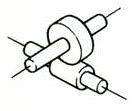
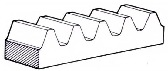
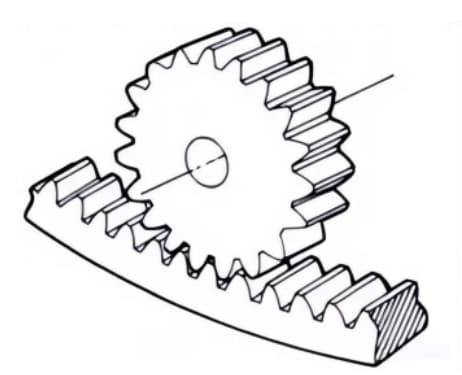
(2) Rack and Pinion
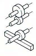
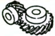
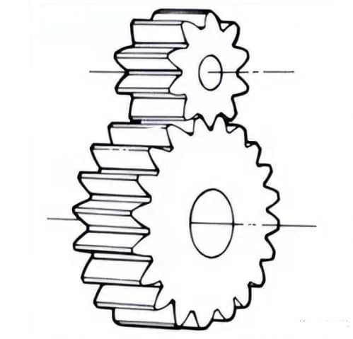
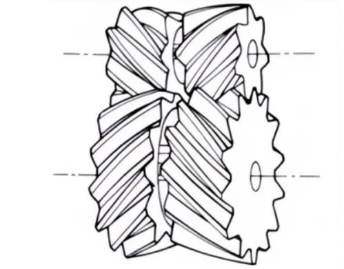
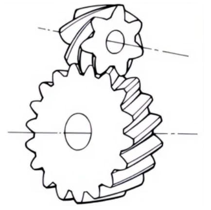
(3) Helical Gear with Crossed Axes
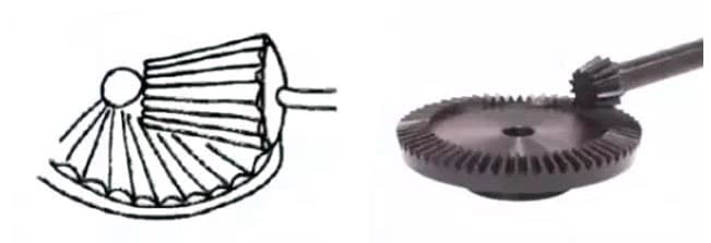
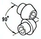
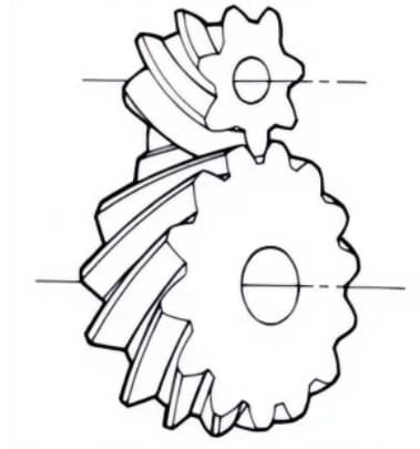
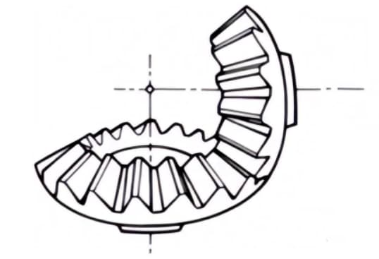
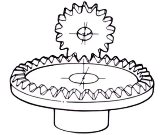
(4) Bevel Gear
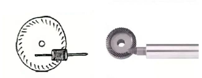
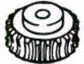
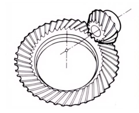
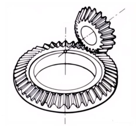
(5) High Transmission Ratio Hypoid Bevel Gear
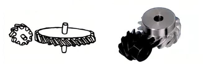
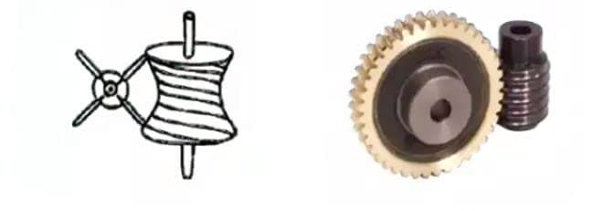
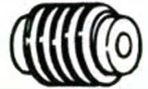
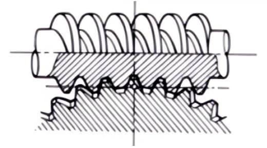
(6) Worm Gear
It wasn’t until the late 17th century that people began to study the wheel’s tooth shape, which could accurately transmit motion. After the Industrial Revolution in Europe in the 18th century, the application of gear transmission became increasingly widespread.
First, the cycloidal gear was developed, followed by the involute gear. By the beginning of the 20th century, the involute gear had become dominant in its application. Later, gears like the helical gear, arc gear, bevel gear, and skew gear were developed.
Today, modern gear technology has made great advancements. Gear modules range from 0.004 to 100 millimeters, the gear diameter can range from 1 millimeter to 150 meters. The power transmission capability can reach up to 100,000 kilowatts, and the rotational speed can be as high as 100,000 revolutions per minute. The highest circumferential speed can reach up to 300 meters per second.
Internationally, power transmission gear devices are developing towards miniaturization, high speed, and standardization. Some trends in gear design include the application of special gears, the development of planetary gear devices, and the research and development of low vibration and low noise gear systems.
3. Gears are generally divided into three main categories.
There are various types of gears, and the most common method of classification is based on the axis of the gear.
Generally, gears are classified into three types: parallel-axis, intersecting-axis, and skew-axis.
Parallel-axis gears: including spur gears, helical gears, internal gears, racks, and helical racks.
Intersecting-axis gears: including straight bevel gears, spiral bevel gears, zero-degree bevel gears, etc.
Skew-axis gears: including helical gears with crossed axes, worm gears, hypoid bevel gears, etc.
Type of Gear Transmission
Type of Gear
Transmission Efficiency (%)
3D Graphical Representation
Parallel-axis
Spur gears
98.0-99.5
Helical gears
Racks,Helical racks
Intemal gears
Intersecting-axis
Miter gears
98.0-99.0
Straight bevel gears
Spiral bevel gears
Skew-axis
Screw gears
70.0-95.0
Worms
30.0-90.0
Worm wheels
The efficiency listed in the above table is the transmission efficiency, which does not include losses from bearings and stirring lubrication. The meshing of parallel-axis and intersecting-axis gear pairs is basically rolling, and the relative sliding is very small, so the efficiency is high.
The meshing of staggered-axis gear pairs, such as helical gears and worm gears, has a significant impact of friction because they achieve power transmission through relative sliding, causing a reduction in transmission efficiency compared with other gears.
The efficiency of gears refers to the transmission efficiency of gears in their normal assembly condition.
If there is improper installation, especially when the distance of bevel gear assembly is incorrect and causes an error at the intersection of the same bevel, its efficiency will significantly decrease.
3.1 Parallel-axis Gears
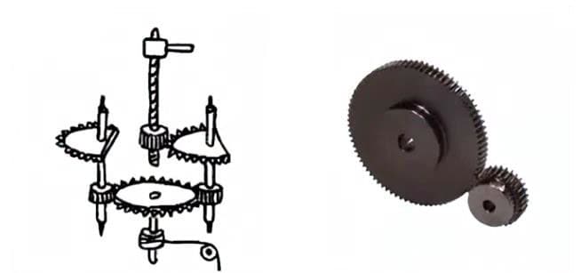
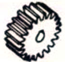
1. Spur Gears
Cylindrical gears for which tooth lines and axial lines are parallel. They are widely used in power transmission because they are easy to process.
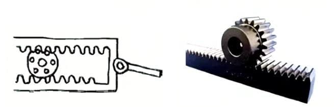
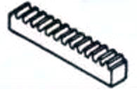
2. Rack
A straight-toothed gear that meshes with spur gears. It can be viewed as a special case where the pitch diameter of the spur gear becomes infinitely large.
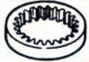
3. Internal Gears
Gears with teeth machined on the inside of a ring that mesh with spur gears. They are mainly used in applications such as planetary gear transmission mechanisms and gear couplings.
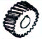
4. Helical Gears
Cylindrical gears with teeth lines in the form of helix. They are widely used because of their high strength and smooth operation, compared to spur gears. They generate axial thrust during transmission.
5. Helical Rack
A rack gear that meshes with helical gears. It is equivalent to the case where the pitch diameter of the helical gear becomes infinitely large.
6. Herringbone Gears
Gears consisting of two helical gears with opposite helix angles. They have the advantage of not generating axial thrust.
3.2 Intersecting-Axis Gears
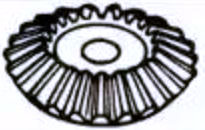
1. Straight Bevel Gears
Bevel gears with tooth lines that are parallel to the generatrix of the cone. They are relatively easy to manufacture compared to other types of bevel gears.
Therefore, they are widely used in bevel gear applications for power transmission.
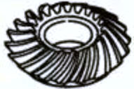
2. Spiral Bevel Gears
Bevel gears with curved tooth lines and a helix angle. Although they are more difficult to manufacture than straight bevel gears, they are widely used as high-strength and low-noise gears.
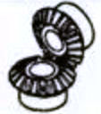
3. Zero Bevel Gears
Curved bevel gears with a helix angle of zero degrees. They have the characteristics of both straight and spiral bevel gears, with the tooth surface subjected to the same force situation as straight bevel gears.
3.3 Staggered-Axis Gears
1. Worm Gear Pair
The term “worm gear pair” refers to a combination of a worm and a worm wheel that meshes with it. The biggest characteristic of the worm gear pair is that a large transmission ratio can be obtained with just one pair, and they operate quietly. However, their low efficiency is a disadvantage.
2. Helical Gear and Worm Gear Pair
A term used when cylindrical worm gear pairs are used for transmission between staggered axes. They can be used in the case of helical gear pairs or between helical and spur gear pairs. Although they operate smoothly, they are only suitable for use under light loads.
3.4 Other Special Gears
1. Face Gears
Disk-shaped gears that can mesh with spur gears or helical gears. They are used for transmission between orthogonal axes and staggered axes.
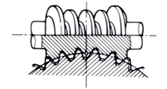
2. Hourglass Worm Gear Pair
The term “hourglass worm gear pair” refers to a combination of an hourglass worm and a worm wheel that meshes with it. Although they are more difficult to manufacture compared to cylindrical worm gear pairs, they can transmit heavy loads.
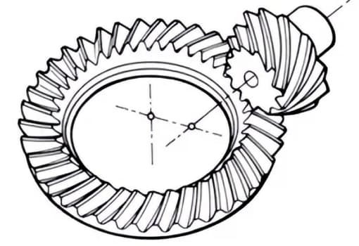
3. Hypoid Gears
Conical gears used for transmission between staggered axes. The larger and smaller gears are machined eccentrically, similar to the case of spiral bevel gears. The meshing principle is very complex.
4. Basic Terminology and Dimension Calculations of Gears
Gears have distinctive terminology and presentation methods. In order to enhance the understanding of gears, here are some commonly used basic gear terminology.
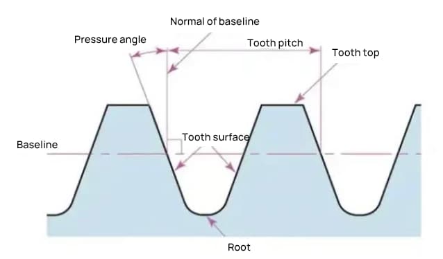
1. Names of gear parts
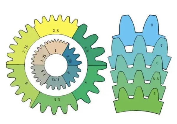
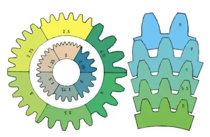
2. The term used to indicate the size of a gear is called the module
m1, m3, m8… are known as module 1, module 3, module 8 respectively. The module is universally used worldwide to indicate the size of the gear, using the symbol m (module) and numbers (millimeters) to represent the size of the teeth.
The larger the number, the larger the gear.
In countries that use imperial units, such as the United States, the size of the teeth is indicated by the symbol DP (diametral pitch) and numbers (the number of teeth for a gear with 1 inch pitch diameter).
For example: DP24, DP8 etc. There is also a comparison and special method for indicating the size of teeth using the symbol CP (circular pitch) and numbers (millimeters), such as CP5, CP10.
The pitch (p) can be obtained by multiplying the modulus by pi. The pitch is the length between adjacent teeth.
The formula is: p= pi x m
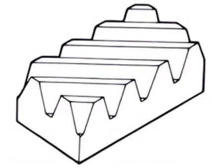
Comparison of teeth size for different modules:
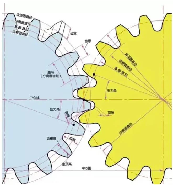
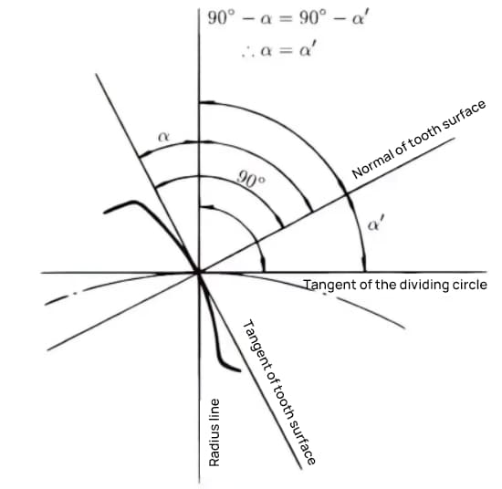
3. Pressure angle
The pressure angle is a parameter that determines the shape of the gear teeth. It refers to the inclination of the gear teeth surface and is generally set at 20 degrees (α).
Previously, gears with a pressure angle of 14.5 degrees were common.
The pressure angle is the angle formed between the radius and the tangent of the tooth shape at a specific point on the tooth surface (generally the node). As shown in the picture, α is the pressure angle. α’ is also a pressure angle since α’ = α.
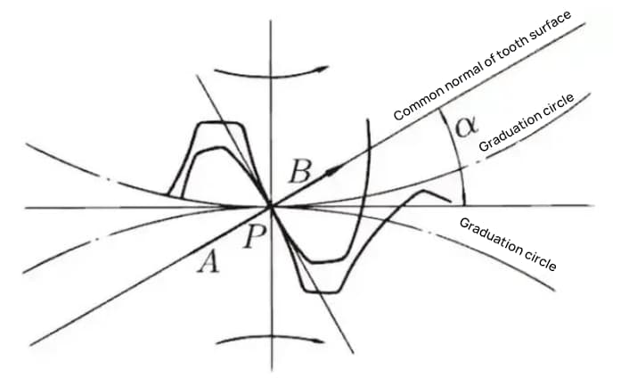
When the meshing state of Gear A and Gear B is viewed from the node, Gear A pushes Gear B from the node. At this time, the driving force acts on the common normal of Gear A and Gear B. In other words, the common normal is the direction of force and the direction of pressure bearing, with α being the pressure angle.
The module (m), pressure angle (α), and number of teeth (z) are the three basic parameters of a gear. On this basis, each part of the gear is calculated in terms of size.
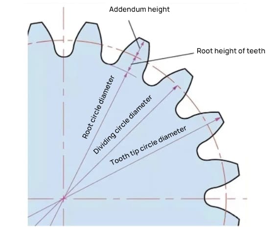
4. Addendum and Dedendum
The height of a gear tooth is determined by the module (m).
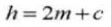
The full tooth height is h=2.25m (= addendum height + dedendum height).
The addendum height (ha) is the height from the tip of the gear tooth to the pitch circle. ha=1m.
The dedendum height (hf) is the height from the root of the gear tooth to the pitch circle. hf=1.25m.
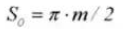
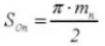
The reference for the thickness of the gear tooth (s) is half the pitch. s=πm/2.
5. Gear Diameter
The parameter that determines the size of a gear is its pitch circle diameter (d). Based on the pitch circle, the pitch, thickness, height, addendum height, and dedendum height of the gear can be determined.
The pitch circle diameter is d=zm.
The addendum circle diameter is da=d+2m.
The dedendum circle diameter is df=d-2.5m.
The pitch circle cannot be seen directly on the actual gear because it is an assumed circle used to determine the size of the gear.
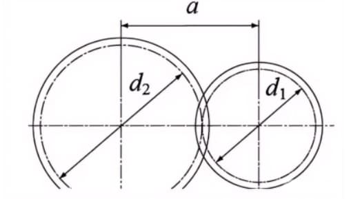
6. Center Distance and Backlash
When the pitch circles of a pair of gears mesh tangentially, the center distance is half the sum of the pitch circle diameters.
Center distance a=(d1+d2)/2
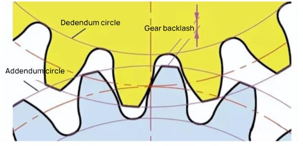
Backlash is an important factor for obtaining smooth meshing of gears during engagement. It is the space between the tooth surfaces when a pair of gears are in mesh.
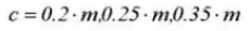
There is also clearance in the direction of gear tooth height. This clearance is known as axial clearance or clearance (c). The clearance (c) is the difference between the root circle diameter of a gear and the tip circle diameter of its mating gear.
Clearance c=1.25m-1m=0.25m
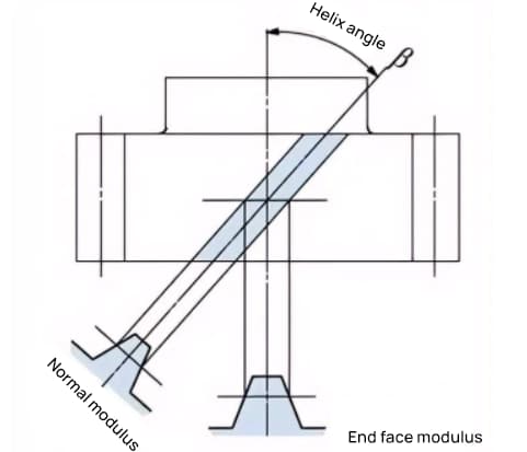
7. Helical Gear
A gear whose teeth are spirally twisted after a spur gear is called a helical gear. Most of the geometric calculations for a spur gear are applicable to a helical gear. There are two types of helical gears based on their reference surfaces:
End face (shaft perpendicular) reference (end face module / pressure angle)
The formula for the relationship between the end face module (mt) and the normal module (mn) is mt=mn/cosβ.
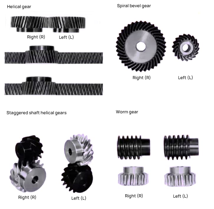
8. Helix Direction and Meshing
For helical gears, such as helical gears and cycloidal gears, whose teeth are helically shaped, the helix direction and meshing are fixed.
Helix direction refers to when the axis of the gear points up and down, the direction of the teeth is to the upper right as “right-hand,” and to the upper left as “left-hand” when viewed from the front. The meshing of various types of gears is shown below.
5. The most commonly used tooth profile for gears is the involute tooth profile.
If teeth with equal spacing are only partitioned on the outer periphery of the friction wheel, fitted with projections, and then meshed and rotated with each other, the following problems may arise:
When the gear transmission needs to be both quiet and smooth, involute curves are used.
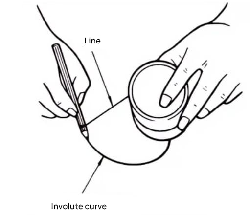
1. What is an involute curve?
An involute curve is a curve obtained by winding a wire with a pencil on the outer periphery of a cylinder and gradually releasing the wire in a tense state.
The curve drawn by the pencil is the involute curve, and the outer periphery of the cylinder is called the base circle.
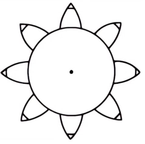
2. An Example of an 8-tooth Involute Gear
Divide the cylinder into 8 equal parts and tie 8 pencils to them to draw 8 involute curves. Then, wind the wires in the opposite direction and draw 8 more curves using the same method. This is an 8-tooth gear with involute curves as its tooth profile.
3. Advantages of Involute Gears
The advantages of involute gears include their ability to transmit a constant speed ratio, smooth operation due to their gradually changing contact pattern, and low sensitivity to center distance variations.
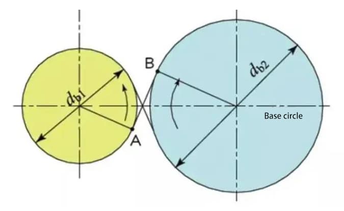
4. Base Circle and Pitch Circle
The base circle is the fundamental circle that forms the involute tooth profile. The pitch circle is the reference circle that determines the size of the gear. The base circle and pitch circle are important geometric dimensions of gears.
The involute tooth profile is a curve formed on the outside of the base circle, and the pressure angle on the base circle is zero.
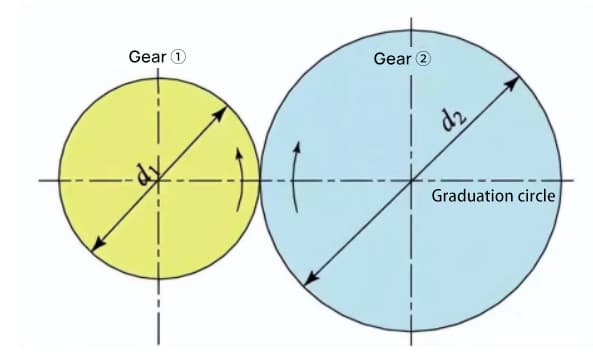
5. Meshing of Involute Gears
When two standard involute gears are meshed, their pitch circles are tangent to each other at the standard center distance. The appearance of the meshing of the two gears looks like the transmission of two friction wheels with diameters of d1 and d2, respectively.
However, the meshing of involute gears actually depends on the base circle rather than the pitch circle.
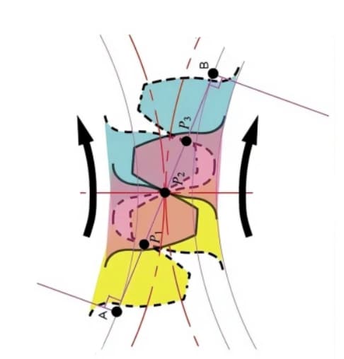
The contact points between the meshing teeth of two gears move along the line of action in the sequence of P1, P2, and P3.
Pay attention to the yellow gear tooth in the driving gear. After this tooth starts meshing, the gear is in a state of two-tooth meshing (P1, P3) for a period of time. The meshing continues, and when the contact point moves to point P2 on the pitch circle, only one tooth remains in mesh.
The meshing continues, and when the contact point moves to point P3, the next gear tooth starts meshing at point P1, forming a two-tooth meshing state again. In this way, the two-tooth meshing and single-tooth meshing of gears interact and repeatedly transmit rotational motion.
The common tangent line between the base circles, A-B, is called the line of action. The contact points of the gear pairs are all on this line of action.
With an illustrative diagram, it is like a belt running on the outer peripheries of two base circles and transmitting power through rotational motion.
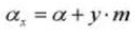
6. Gear displacement is divided into positive displacement and negative displacement.
The tooth profile of the gears we usually use is generally a standard involute, but there are also situations in which the gear teeth need to be displaced, such as adjusting the center distance or preventing undercutting of the smaller gear.
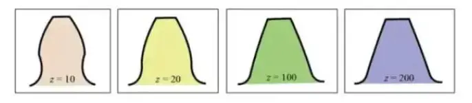
1. Number and Shape of Gear Teeth
The involute tooth form curve varies with the number of teeth. The more teeth there are, the more the tooth form curve tends toward a straight line.
As the number of teeth increases, the tooth root shape becomes thicker, and the strength of the toothed wheel increases.
From the above graph, it can be seen that for a gear with 10 teeth, part of the involute tooth profile at the tooth root is removed, resulting in undercutting.
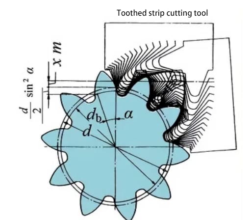
However, by adopting a positive displacement for the gear with z=10, increasing the diameter of the addendum circle and increasing the tooth thickness of the gear teeth, the same gear strength as that of a gear with 200 teeth can be achieved.
2. Displaced gears
The following diagram shows the schematic diagram of a 10-tooth gear with positive displacement. During gear cutting, the amount of tool movement along the radial direction is called the radial displacement amount (referred to as displacement amount) xm(mm).
xm = Displacement amount (mm)
x = Displacement coefficient
m = Module (mm)
Through the positive displacement of the tooth profile, the tooth thickness of the gear increases and the outer diameter (addendum circle diameter) also increases.
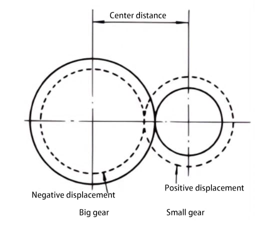
By adopting positive displacement, gear undercutting can be avoided. Displacement of gears can also achieve other purposes, such as changing the center distance. Positive displacement can increase the center distance, while negative displacement can reduce it.
Regardless of whether it is a gear with positive or negative displacement, there are limitations to the displacement amount.
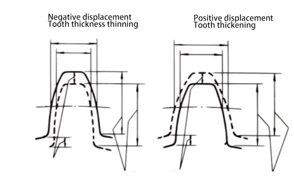
3. Positive and Negative Displacement
Displacement can be positive or negative. Although the tooth height is the same, the tooth thickness is different. A gear with a thickened tooth thickness is a positive displacement gear, while a gear with a reduced tooth thickness is a negative displacement gear.
When it is not possible to change the center distance between two gears, positive displacement can be applied to the smaller gear (to avoid undercutting) and negative displacement to the larger gear, in order to achieve the same center distance. In this case, the absolute value of the displacement amount is equal.
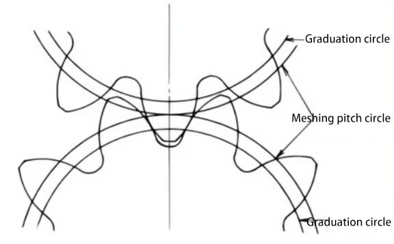
4. Meshing of Displaced Gears
Standard gears mesh when their pitch circles are tangent to each other. The meshing of displaced gears, as shown in the figure, is tangent to each other on the meshing circle.
The pressure angle on the meshing circle is called the meshing angle. The meshing angle is different from the pressure angle on the pitch circle (pitch circle pressure angle), and is an important factor in the design of displaced gears.
5. Function of Gear Displacement
Gear displacement can prevent undercutting caused by a small number of teeth during machining. The desired center distance can be obtained by displacement.
In a pair of gears with a large difference in the number of teeth, positive displacement can be applied to the easily worn smaller gear to increase the tooth thickness, while negative displacement can be applied to the larger gear to reduce the tooth thickness, in order to make the life expectancy of the two gears more comparable.
7. Gear Accuracy
Gears are mechanical components that transmit power and rotation. The main requirements for gear performance are:
In order to meet the above requirements, improving gear accuracy will become a necessary task.
1. Classification of Gear Accuracy
The accuracy of gears can be roughly divided into three categories:
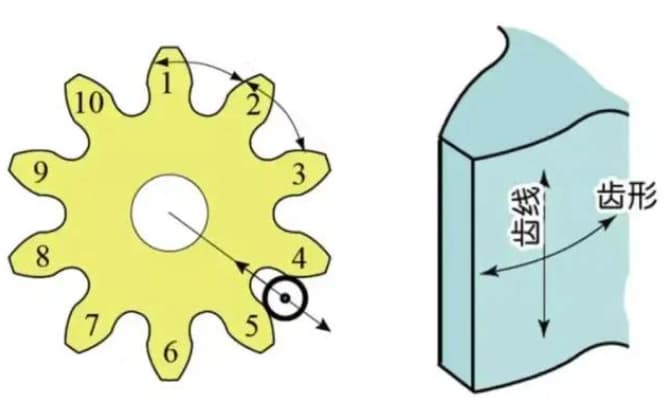
a) Accuracy of involute tooth profile – tooth profile accuracy
b) Accuracy of tooth flank line on the tooth surface – tooth line accuracy
c) Accuracy of teeth/slots position.
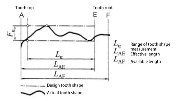
2. Tooth profile error
Tooth profile error refers to the error between the actual tooth profile of the gear and the theoretical tooth profile.
There are many factors that affect the tooth profile error, such as the tool and the machine tool vibrations during the cutting process.
The tooth profile error affects gear meshing performance and noise. Therefore, it is necessary to control the tooth profile error within the allowable range.
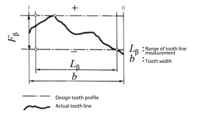
3. Tooth line error
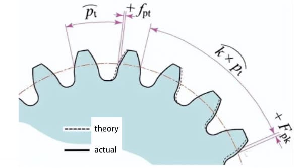
4. Pitch error
Measure the pitch value on the measuring circumference centered on the gear shaft.
Single tooth pitch deviation (fpt) is the difference between the actual pitch and theoretical pitch.
Total cumulative pitch deviation (Fp) is used to evaluate the deviation of the whole gear pitch. The total amplitude value of the pitch cumulative deviation curve represents the total pitch deviation.
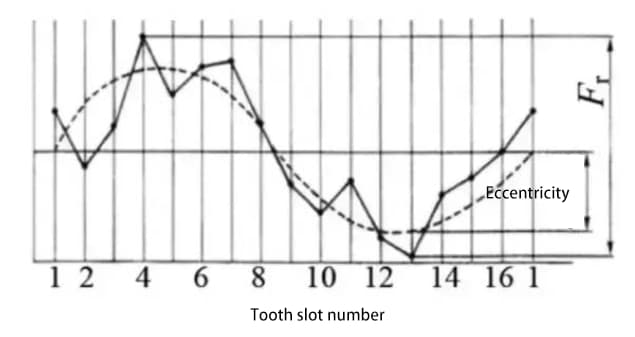
5. Radial Runout (Fr)
Place a probe (either spherical or cylindrical) successively in the teeth groove and measure the difference between the maximum and minimum radial distances from the probe to the gear axis. Eccentricity of the gear shaft is one of the contributing factors to radial runout.
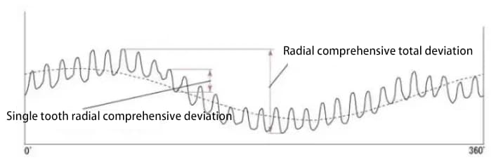
6. Radial Composite Deviation (Fi”)
Up until now, the methods we have described for evaluating the accuracy of gears, such as tooth shape, pitch, and tooth flank accuracy, are all methods for evaluating the accuracy of an individual gear.
In contrast, there is another method that evaluates gear accuracy by performing a two-tooth meshing test on the gear in combination with a measuring gear. The two surfaces of the tested gear mesh with the measuring gear and rotate for an entire cycle. The change in center distance is recorded.
The figure below shows the test results for a gear with 30 teeth. There are a total of 30 wave lines for the single tooth radial composite deviation.
The radial composite deviation value is approximately the sum of radial runout deviation and single tooth radial composite deviation.
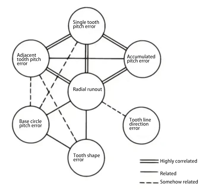
7. The correlation among various accuracy aspects of gears
The various parts of the gear accuracy are related to each other. Generally speaking, radial runout is strongly correlated with other errors, and there is also a strong correlation between various pitch errors.
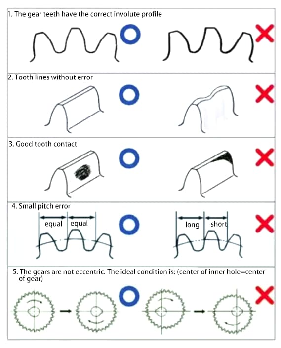
8. The requirements for high precision gears are:
8. Gear calculation formulas:
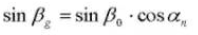
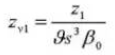
Spiral angle on a normal cylindrical section:
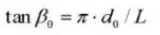
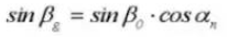
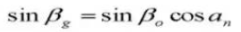
Spiral angle on a base cylinder:
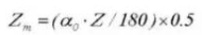
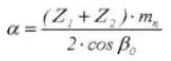
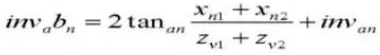
Tooth thickness centering angle:
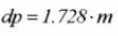
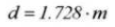
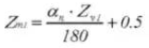
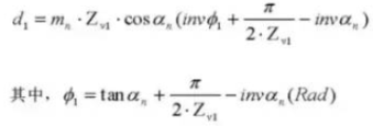
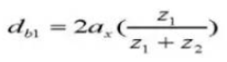
Pin diameter:
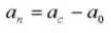
Center distance correction factor:
Calculation of Standard Spur Gears (Pinion Gear ①, Gear Wheel ②)
1. Number of Teeth on Gear Standard
2. Standard Involute Gear Profile Straight Tooth Gear
3. Module m
4. Pressure Angle
5. Number of Teeth
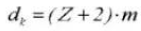
6. Effective Tooth Depth
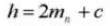
7. Whole Depth of Tooth
8. Cog Clearance
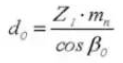
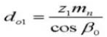
9. Reference Pitch Circle Diameter
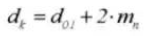
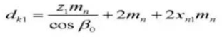
10. Outside Diameter
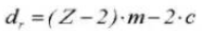
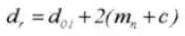
11. Root Diameter
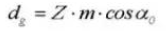
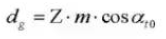
12. Base Circle Diameter
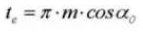
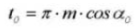
13. Circular Pitch
14. Normal Diametral Pitch
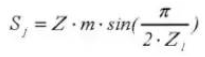
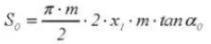
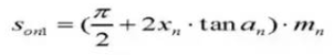
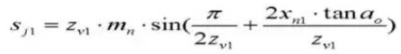
15. Circular Tooth Thickness
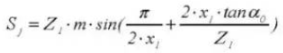
16. Chordal Tooth Thickness
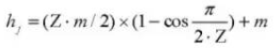
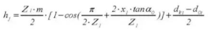
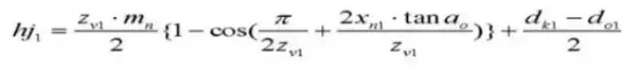
17. Gear oil dipstick tooth height
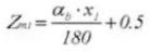
18. Number of Teeth Across
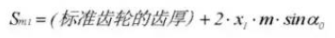
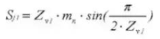
19. Tooth Thickness Across
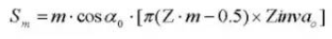
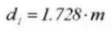
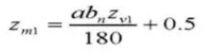
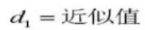
20. Pin Diameter
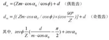
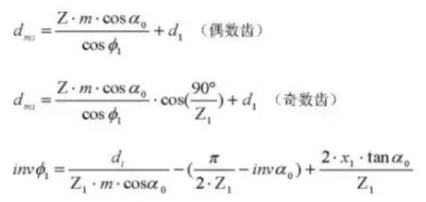
21. Cylindrical Measuring Dimension
Formula for Calculating Displaced Spur Gears (Pinion ①, Gear ②):
1. Gear Tooth Profile Transverse
2. Tool Tooth Profile Contact Ratio
3. Module m
4. Pressure Angle
5. Number of Teeth Z
6. Effective Tooth Depth
7. Whole Depth of Tooth
8. Gear Backlash C
9. Transverse Contact Ratio X
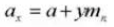
10. Center Distance
11. Reference Pitch Circle Diameter
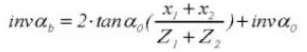
12. Operating Pressure Angle
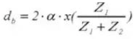
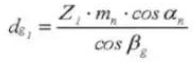
13. Pitch Circle Diameter
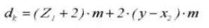
14. Outside Diameter
15. Addendum Diameter
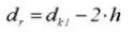
16. Pitch Diameter
17. Circular Pitch
18. Normal Diametral Pitch
19. Circular Tooth Thickness
20. Chordal Tooth Thickness
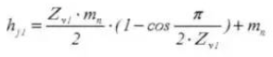
21. Gear Vernier Caliper Tooth Height
22. Number of Teeth Across
23. Tooth Thickness Across
24. Tip Diameter
25. Transverse Measuring Dimension
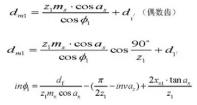
Formula for Calculating Standard Helical Gears (Normal System) (Pinion ①, Gear ②)
1. Gear Tooth Profile Standard
2. Reference Section of Tooth Profile Normal System
3. Tool Tooth Profile Helical Gear
4. Module
5. Pressure Angle
6. Number of Teeth
7. Helix Direction
8. Effective Tooth Depth
9. Whole Depth of Tooth
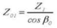
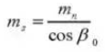
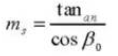
10. Front Pressure Angle
11. Center Distance
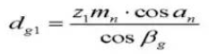
12. Reference Pitch Circle Diameter
13. Outside Diameter
14. Root Diameter
15. Pitch Diameter
16. Helix Angle on Base Circle
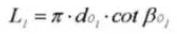
17. Pitch
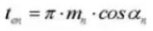
18. Circular Pitch (Normal System)
19. Normal Diametral Pitch (Normal System)
20. Circular Tooth Thickness (Normal System)
21. Equivalent Number of Teeth on a Standard Spur Gear
22. Chordal Tooth Thickness
23. Gear Vernier Caliper Tooth Depth
24. Number of Teeth Across
25. Tooth Thickness Across
26. Tip Diameter
27. Cylindrical Measuring Dimension
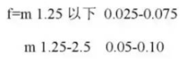
28. Gear Backlash f
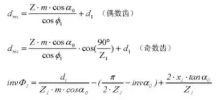
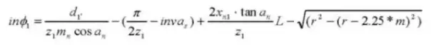
Formula for Calculating Displaced Helical Gears (Normal System) (Pinion ①, Gear ②):
1. Gear Tooth Profile Displaced
2. Reference Section of Tooth Profile Normal System
3. Tool Tooth Profile Helical Gear
4. Module (Normal System)
5. Pressure Angle (Normal System)
6. Number of Teeth
7. Helix Direction
8. Effective Tooth Depth
9. Whole Depth of Tooth
10. Transverse Contact Ratio
11. Center Distance
12. Normal Module
13. Front Pressure Angle (Normal System)
14. Equivalent Number of Teeth on a Standard Spur Gear
As the founder of MachineMFG, I have dedicated over a decade of my career to the metalworking industry. My extensive experience has allowed me to become an expert in the fields of sheet metal fabrication, machining, mechanical engineering, and machine tools for metals. I am constantly thinking, reading, and writing about these subjects, constantly striving to stay at the forefront of my field. Let my knowledge and expertise be an asset to your business.
Attention all mechanical engineers and manufacturing professionals! Are you struggling with pesky anodizing defects in your aluminum products? Look no further! In this blog post, we'll dive deep into the…
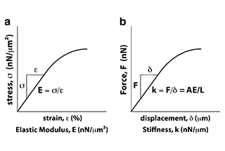
Ever wondered why some materials bend easily while others remain rigid? This blog dives into the fascinating world of elastic modulus and stiffness, unraveling their crucial roles in engineering. By…
Have you ever wondered what makes a perfect circle? In the world of mechanical engineering, roundness is a crucial concept that affects the performance and longevity of rotating components. This…
In today's fast-paced manufacturing world, efficient deburring is crucial. With numerous methods available, choosing the right one can be daunting. In this blog post, we'll explore various deburring techniques, from…
Have you ever wondered what keeps the world spinning smoothly? The unsung heroes behind the scenes are bearings. These small but mighty components play a crucial role in reducing friction…
Gears are the unsung heroes of the mechanical world, quietly working behind the scenes to keep machines running smoothly. But have you ever wondered what materials these critical components are…
This article explores the top 5 cooling tower manufacturers shaping our world. Learn how these companies innovate to keep industries running smoothly and efficiently. Get ready to uncover the secrets…
Have you ever wondered what keeps our gas systems running smoothly and safely? In this article, we explore top gas regulator manufacturers, uncovering their innovations and contributions to the industry.…
Ever wondered why connecting copper and aluminum wires is problematic? This article explains the risks associated with connecting these two metals due to their differing electrochemical properties, which can lead…