| Process | Inspection Items: | Property | Quality Standards | Inspection Methods and Instruments |
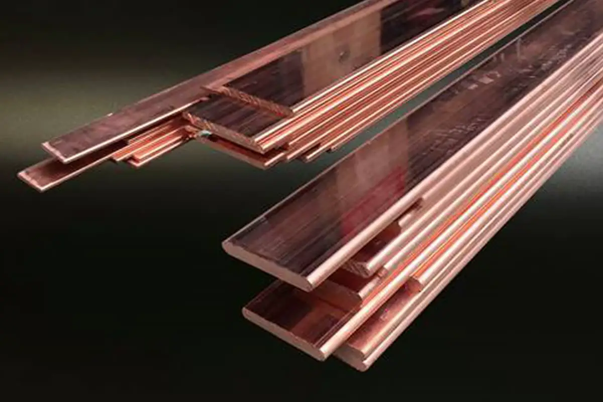
| Busbar Processing Configuration | Visual Inspection | Surface Inspection | | Smooth, free from cracks and creases | Observation and inspection. |
| External Inspection | | Flat, devoid of deformations and twists |
| Threaded Surface Machining | Overlap Length | Mainly | Compliant with GBJ 149-1990 regulations | Check against the standard. Inspect with a ruler. |
| Screw Hole Layout and Specifications | Mainly |
| Center Distance Error Between Screw Holes | | ±0.5mm | Inspect with a ruler. |
| End Face Appearance | | Flat, smooth, free of sharp corners and burrs. | Observation and inspection. |
| Contact Surface Flatness | | Even and void of local depressions. | Measure with a steel ruler. |
| Contact Surface Cross-Section Reduction | Mainly | Copper ≤3%, Aluminum ≤5%. | Inspect with a vernier caliper. |
| Busbar bending | Allowed Minimum Bending Radius | Mainly | In accordance with GBJ 149-1990 regulations. | Check against standards using a template. |
| Minimum Distance from Bending Start Point to Joint Edge | | ≥50mm | Inspect with a ruler. |
| Distance from Bending Start Point to Busbar Supporter Edge | | ≥50mm; ≤0.25 pivot distance. |
| Twisting Length of 90° Bend in mm | | 2.5 to 5 times the width of the busbar |
| Appearance of Bending Part | Mainly | No cracks, no noticeable creases. | Observation and inspection. |
| Bending Radius on the Same Section of Three Phases | | Consistent. | Inspect using a template. |
| Bending Radius of Multiple Busbars in the Same Phase | | Consistent. | Observation and inspection. |
| Bending Radius of Branch Busbars with Same Layout | |
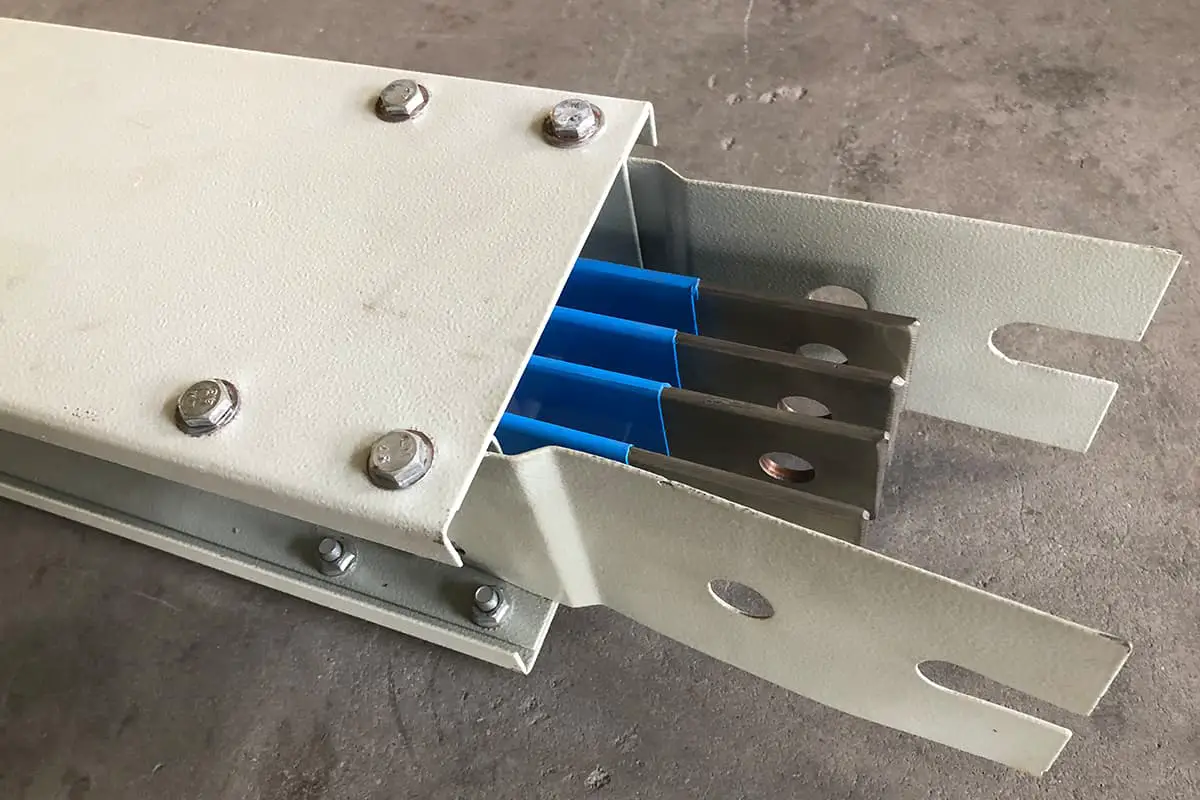
| Busbar Installation | Hardware Installation | Hardware Inspection | | Clean, undamaged. | Observation and inspection. |
| Single-Phase AC Busbar Hardware Connection | Mainly | Secure, with no closed magnetic circuit. |
| Appearance of Fixing Device | | No sharp angles or burrs. |
| Busbar Installation | Gap Between Busbar and Upper Clamp When Busbar is Horizontal | | 1mm~1.5mm | Inspect with a ruler. |
| Distance Between Upper Clamp and Busbar When Busbar is Vertical | | 1.5mm~2mm |
| Stress Check Between Busbar and Support | Mainly | No external stress. | Observation and inspection. |
| Interlayer Gap of Multiple Layers of Busbar in the Same Phase | | Uniform thickness along the generatrix. | Inspect with a ruler. |
| Busbar Fixation Dead Point on Insulator | | Set one for each segment, either along the entire length or at the midpoints of the two expansion sections. | 观察检查 |
| Busbar connection | Distance Between Supporter and Joint Edge | | ≥50mm | Inspect with a ruler. |
| Connections Between Busbars and Between Busbar and Equipment Terminals | Mainly | No external stress | Check during connection. |
| Overlap Surface | Mainly | Smooth, without an oxidation layer, the silver plating must not be ground, coated with electrical load grease. | Observation and inspection. |
| Terminal Connection and Screw Shape | Appearance | Mainly | No spring pads | |
| Flat Washer | |
Tin-coated copper | Observation and inspection. |
| Lock Nut | | Complete and tight-fitting |
| Connecting Bolt | Matched with Hole Diameter | | ≤1mm | Inspect with bolts |
| Bolt Insertion Direction | | When the busbar is laid flat, it goes from bottom to top, and all other nuts are on the maintenance side. | Observation and inspection. |
| Anti-loose Component Appearance | | Complete, intact, and flattened. |
| Tightening Torque | | According to the stipulations of GBJ 149-1990. | Inspect with a torque wrench according to the standard. |
| Exposed Length After Bolt Tightening | | 2~3 buttons | Observation and inspection. |
| Gap Between Adjacent Washers | Mainly | ≥3mm | Observe or inspect with a ruler |
| Installation of Expansion Joint | | No streaking, breakage, or creasing phenomena. | Observation and inspection. |
| Overall inspection | The distance between charged bodies and between charged bodies and other objects. | Mainly | In accordance with GBJ 149-1990 regulations. | Inspect according to the standard using a ruler. |
| Color matching and painting. | | Complete and correct | Observation and inspection. |