0° – 180° Bend Allowance Chart for Sheet Metal Bending
Have you ever wondered how sheet metal parts are designed and manufactured with precision? In this blog post, we'll dive into the fascinating world of bend allowance - a crucial…
Attention all sheet metal fabricators and designers! Are you struggling to determine the optimal bending radius for your projects? Look no further! In this blog post, we’ll dive into the factors that influence bending radius and provide practical guidelines to help you achieve precise and consistent bends. Drawing from the expertise of seasoned professionals, you’ll gain valuable insights and techniques to elevate your sheet metal fabrication skills. Get ready to bend with confidence!
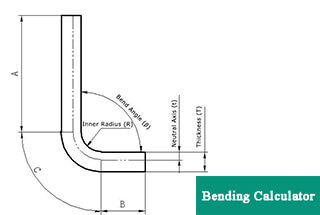
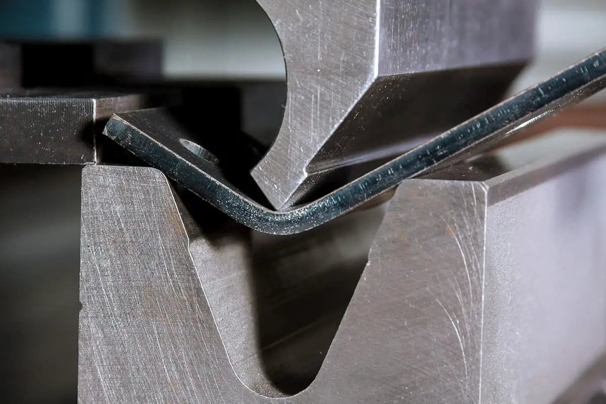
The sheet metal bending radius is a critical value in sheet metal drawing that can be difficult to determine during the actual processing.
This radius is dependent on the material thickness, the pressure of the press brake machine, and the width of the bending die’s lower die groove.
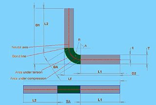
A simple and rough method to determine the bending radius is:
Experience in actual sheet metal processing shows that when the plate thickness is generally no more than 6mm, the inner radius of sheet metal bending can directly use the plate thickness as the radius.
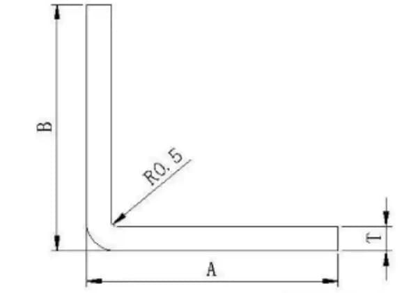
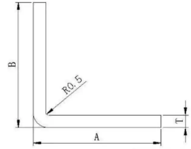
When the bending radius is r = 0.5, the general sheet metal thickness t is equal to 0.5mm.
If a bending radius different from the plate thickness is required, a special die must be used for processing.
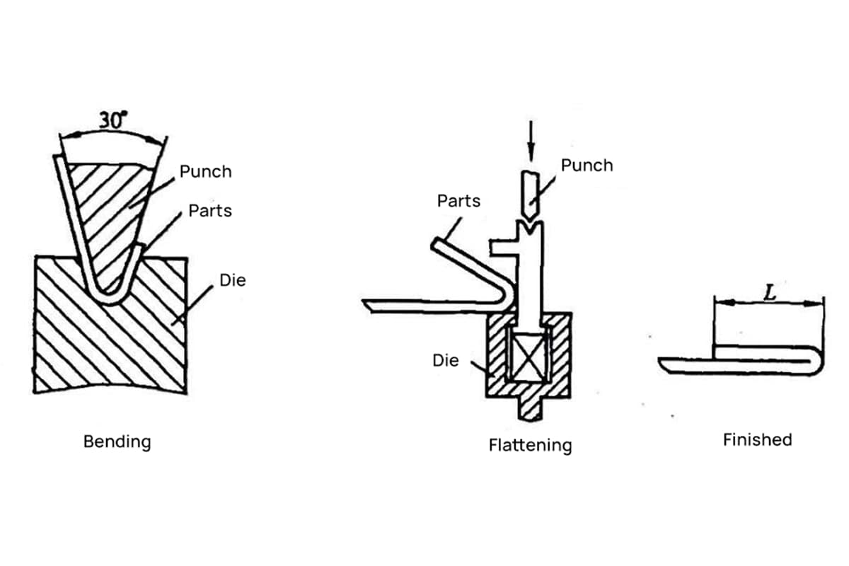
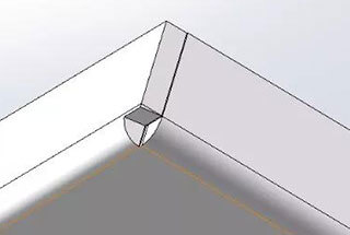
When the sheet metal drawing calls for a 90-degree bend with a particularly small bending radius, the sheet metal should first be grooved and then bent.
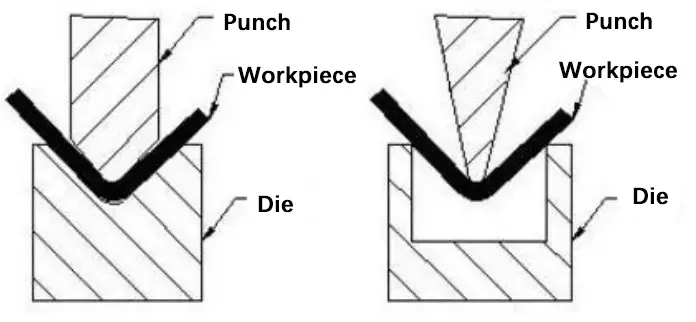
Special press brake tooling, such as punches and dies, can also be used.
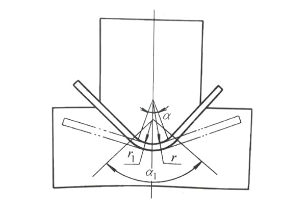
The relationship between the bending radius of sheet metal and the width of the lower die groove of the bending die has been established through numerous experiments in sheet metal processing.
For example, when a 1.0mm plate is bent with an 8mm groove width, the ideal bending radius is R1.
If the groove width is increased to 20mm, the depth of the stretched plate increases, resulting in a larger tensile area and a larger R angle.
To avoid damaging the press brake die and to maintain the desired bending radius, it is recommended to bend with a narrow groove, following the standard ratio of 1:8 between plate thickness and groove width.
The minimum recommended ratio is 1:6 and bending with a ratio of less than 1:4 is not recommended.
Suggestion: If the strength allows, it is preferable to groove first and then bend in order to achieve a small sheet metal bending radius.
The following figure is a table provided by the press brake manufacturer, which shows the corresponding relationship between bending radius, pressure, and minimum bending height.
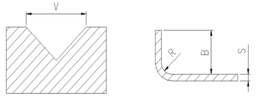
Note: The data with gray scale in the table represents the required bending pressure P (KN/m), and the maximum bending force of the press brake machine is 1700KN. There are five available bending knife edges: V = 12, 16, 25, 40, and 50.
Please refer to your available knife edge and bending length to determine the bending radius, which will help you calculate the accurate length of the material to be unfolded.
The above information pertains to the pressure parameters and bending die width of a single press brake.
The actual calculations should be based on the pressure and bending die of your own sheet metal processing facility.
When considering sheet metal design, it’s important to understand how the bend radius affects your choice of materials. In this section, we’ll discuss some popular material options, such as mild steel, stainless steel, and aluminum alloys.
Mild steel is a versatile material for sheet metal fabrication due to its formability and cost-effectiveness. When bending low carbon steel, you should aim for a minimum bend radius equal to the sheet thickness or greater. Some common thicknesses and their respective minimum bend radii include:
| Thickness | Minimum Bend | Bend Radius |
| (0.02″ | 0.51mm ) | 0.75″ | 19.05mm | 0.605″ | 15.37mm |
| (0.02″ | 0.51mm ) | 0.2″ | 5.08mm | 0.05″ | 1.27mm |
| (0.03″ | 0.76mm ) | 0.2″ | 5.08mm | 0.05″ | 1.27mm |
| (0.25″ | 6.35mm ) | 1.375″ | 34.92mm | 0.17″ | 4.32mm |
| (0.25″ | 6.35mm ) | 1.375″ | 34.92mm | 0.25″ | 6.35mm |
| (0.25″ | 6.35mm ) | 1.5″ | 38.10mm | 0.35″ | 8.89mm |
| (0.25″ | 6.35mm ) | 1.5″ | 38.10mm | 0.25″ | 6.35mm |
| 11 gauge (0.12″ | 3.05mm ) | 1.375″ | 34.92mm | 0.375″ | 9.52mm |
| 11 gauge (0.12″ | 3.05mm ) | 0.75″ | 19.05mm | 0.16″ | 4.06mm |
| 11 gauge (0.12″ | 3.05mm ) | 0.5″ | 12.70mm | 0.115″ | 2.92mm |
| 11 gauge (0.12″ | 3.05mm ) | 0.5″ | 12.70mm | 0.085″ | 2.16mm |
| 11 gauge (0.12″ | 3.05mm ) | 0.5″ | 12.70mm | 0.06″ | 1.52mm |
| 11 gauge (0.12″ | 3.05mm ) | 0.5″ | 12.70mm | 0.06″ | 1.52mm |
| 11 gauge (0.12″ | 3.05mm ) | 0.5″ | 12.70mm | 0.045″ | 1.14mm |
| 12 gauge (0.105″ | 2.67mm ) | 0.5″ | 12.70mm | 0.085″ | 2.16mm |
| 12 gauge (0.105″ | 2.67mm ) | 0.5″ | 12.70mm | 0.07″ | 1.78mm |
| 12 gauge (0.105″ | 2.67mm ) | 0.5″ | 12.70mm | 0.065″ | 1.65mm |
| 12 gauge (0.105″ | 2.67mm ) | 0.5″ | 12.70mm | 0.05″ | 1.27mm |
| 13 gauge (0.09″ | 2.29mm ) | 0.375″ | 9.52mm | 0.045″ | 1.14mm |
| 13 gauge (0.09″ | 2.29mm ) | 0.375″ | 9.52mm | 0.04″ | 1.02mm |
| 13 gauge (0.09″ | 2.29mm ) | 1.375″ | 34.92mm | 0.28″ | 7.11mm |
| 13 gauge (0.09″ | 2.29mm ) | 0.375″ | 9.52mm | 0.055″ | 1.40mm |
| 13 gauge (0.09″ | 2.29mm ) | 0.5″ | 12.70mm | 0.065″ | 1.65mm |
| 13 gauge (0.09″ | 2.29mm ) | 0.5″ | 12.70mm | 0.08″ | 2.03mm |
| 13 gauge (0.09″ | 2.29mm ) | 0.5″ | 12.70mm | 0.075″ | 1.90mm |
| 13 gauge (0.09″ | 2.29mm ) | 0.375″ | 9.52mm | 0.06″ | 1.52mm |
| 13 gauge (0.09″ | 2.29mm ) | 0.375″ | 9.52mm | 0.05″ | 1.27mm |
| 13 gauge (0.09″ | 2.29mm ) | 1.375″ | 34.92mm | 0.375″ | 9.52mm |
| 13 gauge (0.09″ | 2.29mm ) | 0.5″ | 12.70mm | 0.08″ | 2.03mm |
| 13 gauge (0.09″ | 2.29mm ) | 0.5″ | 12.70mm | 0.06″ | 1.52mm |
| 14 gauge (0.075″ | 1.90mm ) | 0.375″ | 9.52mm | 0.04″ | 1.02mm |
| 14 gauge (0.075″ | 1.90mm ) | 0.3″ | 7.62mm | 0.062″ | 1.57mm |
| 14 gauge (0.075″ | 1.90mm ) | 1.375″ | 34.92mm | 0.375″ | 9.52mm |
| 14 gauge (0.075″ | 1.90mm ) | 0.275″ | 6.98mm | 0.062″ | 1.57mm |
| 14 gauge (0.075″ | 1.90mm ) | 0.3″ | 7.62mm | 0.04″ | 1.02mm |
| 14 gauge (0.075″ | 1.90mm ) | 0.3″ | 7.62mm | 0.06″ | 1.52mm |
| 14 gauge (0.075″ | 1.90mm ) | 0.5″ | 12.70mm | 0.08″ | 2.03mm |
| 14 gauge (0.075″ | 1.90mm ) | 0.375″ | 9.52mm | 0.06″ | 1.52mm |
| 14 gauge (0.075″ | 1.90mm ) | 0.3″ | 7.62mm | 0.045″ | 1.14mm |
| 14 gauge (0.075″ | 1.90mm ) | 0.3″ | 7.62mm | 0.055″ | 1.40mm |
| 14 gauge (0.075″ | 1.90mm ) | 0.5″ | 12.70mm | 0.1″ | 2.54mm |
| 14 gauge (0.075″ | 1.90mm ) | 0.5″ | 12.70mm | 0.125″ | 3.18mm |
| 16 gauge (0.06″ | 1.52mm ) | 0.2″ | 5.08mm | 0.045″ | 1.14mm |
| 16 gauge (0.06″ | 1.52mm ) | 0.3″ | 7.62mm | 0.06″ | 1.52mm |
| 16 gauge (0.06″ | 1.52mm ) | 1.5″ | 38.10mm | 0.995″ | 25.27mm |
| 16 gauge (0.06″ | 1.52mm ) | 0.375″ | 9.52mm | 0.075″ | 1.90mm |
| 16 gauge (0.06″ | 1.52mm ) | 0.2″ | 5.08mm | 0.04″ | 1.02mm |
| 16 gauge (0.06″ | 1.52mm ) | 0.265″ | 6.73mm | 0.05″ | 1.27mm |
| 16 gauge (0.06″ | 1.52mm ) | 0.5″ | 12.70mm | 0.24″ | 6.10mm |
| 16 gauge (0.06″ | 1.52mm ) | 0.265″ | 6.73mm | 0.055″ | 1.40mm |
| 16 gauge (0.06″ | 1.52mm ) | 0.265″ | 6.73mm | 0.062″ | 1.57mm |
| 16 gauge (0.06″ | 1.52mm ) | 0.375″ | 9.52mm | 0.065″ | 1.65mm |
| 16 gauge (0.06″ | 1.52mm ) | 0.5″ | 12.70mm | 0.08″ | 2.03mm |
| 16 gauge (0.06″ | 1.52mm ) | 0.3″ | 7.62mm | 0.055″ | 1.40mm |
| 16 gauge (0.06″ | 1.52mm ) | 0.5″ | 12.70mm | 0.125″ | 3.18mm |
| 16 gauge (0.06″ | 1.52mm ) | 1.5″ | 38.10mm | 0.985″ | 25.02mm |
| 16 gauge (0.06″ | 1.52mm ) | 0.55″ | 13.97mm | 0.03″ | 0.76mm |
| 16 gauge (0.06″ | 1.52mm ) | 0.3″ | 7.62mm | 0.062″ | 1.57mm |
| 16 gauge (0.06″ | 1.52mm ) | 1.375″ | 34.92mm | 0.375″ | 9.52mm |
| 18 gauge (0.048″ | 1.22mm ) | 0.3″ | 7.62mm | 0.06″ | 1.52mm |
| 18 gauge (0.048″ | 1.22mm ) | 0.265″ | 6.73mm | 0.05″ | 1.27mm |
| 18 gauge (0.048″ | 1.22mm ) | 0.2″ | 5.08mm | 0.03″ | 0.76mm |
| 18 gauge (0.048″ | 1.22mm ) | 0.375″ | 9.52mm | 0.05″ | 1.27mm |
| 18 gauge (0.048″ | 1.22mm ) | 0.265″ | 6.73mm | 0.065″ | 1.65mm |
| 18 gauge (0.048″ | 1.22mm ) | 0.2″ | 5.08mm | 0.04″ | 1.02mm |
| 18 gauge (0.048″ | 1.22mm ) | 1.5″ | 38.10mm | 1.1″ | 27.94mm |
| 18 gauge (0.048″ | 1.22mm ) | 0.375″ | 9.52mm | 0.125″ | 3.18mm |
| 18 gauge (0.048″ | 1.22mm ) | 0.55″ | 13.97mm | 0.03″ | 0.76mm |
| 18 gauge (0.048″ | 1.22mm ) | 0.265″ | 6.73mm | 0.062″ | 1.57mm |
| 18 gauge (0.048″ | 1.22mm ) | 0.2″ | 5.08mm | 0.045″ | 1.14mm |
| 18 gauge (0.048″ | 1.22mm ) | 0.5″ | 12.70mm | 0.12″ | 3.05mm |
| 18 gauge (0.048″ | 1.22mm ) | 0.3″ | 7.62mm | 0.04″ | 1.02mm |
| 18 gauge (0.048″ | 1.22mm ) | 1.375″ | 34.92mm | 0.375″ | 9.52mm |
| 18 gauge (0.048″ | 1.22mm ) | 0.5″ | 12.70mm | 0.105″ | 2.67mm |
| 20 gauge (0.036″ | 0.91mm ) | 0.5″ | 12.70mm | 0.11″ | 2.79mm |
| 20 gauge (0.036″ | 0.91mm ) | 0.265″ | 6.73mm | 0.055″ | 1.40mm |
| 20 gauge (0.036″ | 0.91mm ) | 0.2″ | 5.08mm | 0.05″ | 1.27mm |
| 20 gauge (0.036″ | 0.91mm ) | 0.2″ | 5.08mm | 0.04″ | 1.02mm |
| 20 gauge (0.036″ | 0.91mm ) | 0.2″ | 5.08mm | 0.035″ | 0.89mm |
| 20 gauge (0.036″ | 0.91mm ) | 0.375″ | 9.52mm | 0.07″ | 1.78mm |
| 20 gauge (0.036″ | 0.91mm ) | 0.55″ | 13.97mm | 0.03″ | 0.76mm |
| 20 gauge (0.036″ | 0.91mm ) | 0.265″ | 6.73mm | 0.065″ | 1.65mm |
| 20 gauge (0.036″ | 0.91mm ) | 1.375″ | 34.92mm | 0.375″ | 9.52mm |
| 22 gauge (0.03″ | 0.76mm ) | 0.5″ | 12.70mm | 0.09″ | 2.29mm |
| 22 gauge (0.03″ | 0.76mm ) | 0.2″ | 5.08mm | 0.05″ | 1.27mm |
| 22 gauge (0.03″ | 0.76mm ) | 0.2″ | 5.08mm | 0.04″ | 1.02mm |
| 22 gauge (0.03″ | 0.76mm ) | 0.265″ | 6.73mm | 0.055″ | 1.40mm |
| 22 gauge (0.03″ | 0.76mm ) | 0.265″ | 6.73mm | 0.065″ | 1.65mm |
| 22 gauge (0.03″ | 0.76mm ) | 0″ | 0.00mm | 0.025″ | 0.64mm |
| 22 gauge (0.03″ | 0.76mm ) | 0.265″ | 6.73mm | 0.07″ | 1.78mm |
| 22 gauge (0.03″ | 0.76mm ) | 0.375″ | 9.52mm | 0.085″ | 2.16mm |
Keep in mind that tighter bends can lead to cracks or distortions in the material. Thicker sheets may also require increased force during the bending process.
Stainless steel is known for its corrosion resistance and durability. For most stainless steel grades, you’ll need a larger bend radius compared to low carbon steel. The ratio of the bend radius to the sheet thickness typically varies between 1:1 and 2:1, depending on factors like the type, hardness, and thickness of the stainless steel. Some guidelines for minimum bend radii include:
| Thickness | Minimum Bend | Bend Radius |
| (0.12″ | 3.05mm ) | 0.75″ | 19.05mm | 0.22″ | 5.59mm |
| (0.12″ | 3.05mm ) | 1.5″ | 38.10mm | 1.05″ | 26.67mm |
| (0.12″ | 3.05mm ) | 0.75″ | 19.05mm | 0.2″ | 5.08mm |
| (0.125″ | 3.18mm ) | 0.5″ | 12.70mm | 0.09″ | 2.29mm |
| (0.125″ | 3.18mm ) | 0.5″ | 12.70mm | 0.08″ | 2.03mm |
| (0.125″ | 3.18mm ) | 0.5″ | 12.70mm | 0.125″ | 3.18mm |
| (0.125″ | 3.18mm ) | 0.5″ | 12.70mm | 0.1″ | 2.54mm |
| 12 gauge (0.109″ | 2.77mm ) | 0.5″ | 12.70mm | 0.06″ | 1.52mm |
| 12 gauge (0.109″ | 2.77mm ) | 0.5″ | 12.70mm | 0.095″ | 2.41mm |
| 12 gauge (0.109″ | 2.77mm ) | 0.75″ | 19.05mm | 0.18″ | 4.57mm |
| 12 gauge (0.109″ | 2.77mm ) | 0.5″ | 12.70mm | 0.095″ | 2.41mm |
| 12 gauge (0.109″ | 2.77mm ) | 0.75″ | 19.05mm | 0.22″ | 5.59mm |
| 14 gauge (0.078″ | 1.98mm ) | 0.275″ | 6.98mm | 0.062″ | 1.57mm |
| 14 gauge (0.078″ | 1.98mm ) | 1.375″ | 34.92mm | 0.4″ | 10.16mm |
| 14 gauge (0.078″ | 1.98mm ) | 0.3″ | 7.62mm | 0.05″ | 1.27mm |
| 14 gauge (0.078″ | 1.98mm ) | 0.275″ | 6.98mm | 0.075″ | 1.90mm |
| 14 gauge (0.078″ | 1.98mm ) | 0.375″ | 9.52mm | 0.07″ | 1.78mm |
| 14 gauge (0.078″ | 1.98mm ) | 0.5″ | 12.70mm | 0.11″ | 2.79mm |
| 14 gauge (0.078″ | 1.98mm ) | 0.5″ | 12.70mm | 0.12″ | 3.05mm |
| 14 gauge (0.078″ | 1.98mm ) | 0.5″ | 12.70mm | 0.13″ | 3.30mm |
| 14 gauge (0.078″ | 1.98mm ) | 0.5″ | 12.70mm | 0.09″ | 2.29mm |
| 14 gauge (0.078″ | 1.98mm ) | 0.275″ | 6.98mm | 0.05″ | 1.27mm |
| 14 gauge (0.078″ | 1.98mm ) | 0.5″ | 12.70mm | 0.115″ | 2.92mm |
| 14 gauge (0.078″ | 1.98mm ) | 0.75″ | 19.05mm | 0.26″ | 6.60mm |
| 14 gauge (0.078″ | 1.98mm ) | 0.375″ | 9.52mm | 0.105″ | 2.67mm |
| 14 gauge (0.078″ | 1.98mm ) | 1.5″ | 38.10mm | 1.125″ | 28.58mm |
| 14 gauge (0.078″ | 1.98mm ) | 0.3″ | 7.62mm | 0.055″ | 1.40mm |
| 16 gauge (0.063″ | 1.60mm ) | 0.5″ | 12.70mm | 0.25″ | 6.35mm |
| 16 gauge (0.063″ | 1.60mm ) | 0.5″ | 12.70mm | 0.04″ | 1.02mm |
| 16 gauge (0.063″ | 1.60mm ) | 0.2″ | 5.08mm | 0.04″ | 1.02mm |
| 16 gauge (0.063″ | 1.60mm ) | 0.3″ | 7.62mm | 0.05″ | 1.27mm |
| 16 gauge (0.063″ | 1.60mm ) | 0.5″ | 12.70mm | 0.12″ | 3.05mm |
| 16 gauge (0.063″ | 1.60mm ) | 0.3″ | 7.62mm | 0.055″ | 1.40mm |
| 16 gauge (0.063″ | 1.60mm ) | 0.3″ | 7.62mm | 0.08″ | 2.03mm |
| 16 gauge (0.063″ | 1.60mm ) | 0.265″ | 6.73mm | 0.055″ | 1.40mm |
| 16 gauge (0.063″ | 1.60mm ) | 0.375″ | 9.52mm | 0.07″ | 1.78mm |
| 16 gauge (0.063″ | 1.60mm ) | 0.2″ | 5.08mm | 0.05″ | 1.27mm |
| 16 gauge (0.063″ | 1.60mm ) | 0.265″ | 6.73mm | 0.075″ | 1.90mm |
| 16 gauge (0.063″ | 1.60mm ) | 0.2″ | 5.08mm | 0.05″ | 1.27mm |
| 16 gauge (0.063″ | 1.60mm ) | 0.265″ | 6.73mm | 0.08″ | 2.03mm |
| 16 gauge (0.063″ | 1.60mm ) | 0.5″ | 12.70mm | 0.1″ | 2.54mm |
| 16 gauge (0.063″ | 1.60mm ) | 0.2″ | 5.08mm | 0.035″ | 0.89mm |
| 16 gauge (0.063″ | 1.60mm ) | 0.5″ | 12.70mm | 0.105″ | 2.67mm |
| 18 gauge (0.05″ | 1.27mm ) | 0.2″ | 5.08mm | 0.05″ | 1.27mm |
| 18 gauge (0.05″ | 1.27mm ) | 0.5″ | 12.70mm | 0.04″ | 1.02mm |
| 18 gauge (0.05″ | 1.27mm ) | 0.5″ | 12.70mm | 0.12″ | 3.05mm |
| 18 gauge (0.05″ | 1.27mm ) | 0.5″ | 12.70mm | 0.115″ | 2.92mm |
| 18 gauge (0.05″ | 1.27mm ) | 0.3″ | 7.62mm | 0.07″ | 1.78mm |
| 18 gauge (0.05″ | 1.27mm ) | 0.375″ | 9.52mm | 0.1″ | 2.54mm |
| 18 gauge (0.05″ | 1.27mm ) | 0.3″ | 7.62mm | 0.06″ | 1.52mm |
| 18 gauge (0.05″ | 1.27mm ) | 0.2″ | 5.08mm | 0.045″ | 1.14mm |
| 18 gauge (0.05″ | 1.27mm ) | 0.265″ | 6.73mm | 0.08″ | 2.03mm |
| 18 gauge (0.05″ | 1.27mm ) | 0.5″ | 12.70mm | 0.12″ | 3.05mm |
| 18 gauge (0.05″ | 1.27mm ) | 0.375″ | 9.52mm | 0.125″ | 3.18mm |
| 18 gauge (0.05″ | 1.27mm ) | 0.5″ | 12.70mm | 0.24″ | 6.10mm |
| 18 gauge (0.05″ | 1.27mm ) | 0.265″ | 6.73mm | 0.085″ | 2.16mm |
| 18 gauge (0.05″ | 1.27mm ) | 1.375″ | 34.92mm | 0.4″ | 10.16mm |
| 18 gauge (0.05″ | 1.27mm ) | 0.2″ | 5.08mm | 0.04″ | 1.02mm |
| 18 gauge (0.05″ | 1.27mm ) | 0.265″ | 6.73mm | 0.06″ | 1.52mm |
| 18 gauge (0.05″ | 1.27mm ) | 0.375″ | 9.52mm | 0.09″ | 2.29mm |
| 18 gauge (0.05″ | 1.27mm ) | 0.3″ | 7.62mm | 0.08″ | 2.03mm |
| 20 gauge (0.038″ | 0.97mm ) | 0.3″ | 7.62mm | 0.06″ | 1.52mm |
| 20 gauge (0.038″ | 0.97mm ) | 0.5″ | 12.70mm | 0.125″ | 3.18mm |
| 20 gauge (0.038″ | 0.97mm ) | 0.5″ | 12.70mm | 0.11″ | 2.79mm |
| 20 gauge (0.038″ | 0.97mm ) | 0.5″ | 12.70mm | 0.1″ | 2.54mm |
| 20 gauge (0.038″ | 0.97mm ) | 0.375″ | 9.52mm | 0.095″ | 2.41mm |
| 20 gauge (0.038″ | 0.97mm ) | 0.2″ | 5.08mm | 0.05″ | 1.27mm |
| 20 gauge (0.038″ | 0.97mm ) | 0.3″ | 7.62mm | 0.07″ | 1.78mm |
| 20 gauge (0.038″ | 0.97mm ) | 0.265″ | 6.73mm | 0.07″ | 1.78mm |
| 20 gauge (0.038″ | 0.97mm ) | 0.5″ | 12.70mm | 0.4″ | 10.16mm |
| 22 gauge (0.031″ | 0.79mm ) | 0.55″ | 13.97mm | 0.03″ | 0.76mm |
| 22 gauge (0.031″ | 0.79mm ) | 0.265″ | 6.73mm | 0.08″ | 2.03mm |
| 22 gauge (0.031″ | 0.79mm ) | 0.375″ | 9.52mm | 0.08″ | 2.03mm |
| 22 gauge (0.031″ | 0.79mm ) | 0.3″ | 7.62mm | 0.08″ | 2.03mm |
| 22 gauge (0.031″ | 0.79mm ) | 0.5″ | 12.70mm | 0.09″ | 2.29mm |
| 22 gauge (0.031″ | 0.79mm ) | 0.3″ | 7.62mm | 0.075″ | 1.90mm |
| 22 gauge (0.031″ | 0.79mm ) | 0.2″ | 5.08mm | 0.04″ | 1.02mm |
| 22 gauge (0.031″ | 0.79mm ) | 0.2″ | 5.08mm | 0.05″ | 1.27mm |
| 24 gauge (0.024″ | 0.61mm ) | 0.2″ | 5.08mm | 0.04″ | 1.02mm |
| 24 gauge (0.024″ | 0.61mm ) | 0.265″ | 6.73mm | 0.08″ | 2.03mm |
| 24 gauge (0.025″ | 0.64mm ) | 0.5″ | 12.70mm | 0.1″ | 2.54mm |
Remember to consider the grade and properties of your chosen stainless steel when determining the appropriate bend radius for your application.
Aluminum alloys offer lightweight, strong, and corrosion-resistant options for sheet metal fabrication. Similar to low carbon steel, the minimum bend radius for aluminum alloys is typically equal to the sheet thickness. However, some specific alloys can exhibit better or worse formability. Here’s a general guide to minimum bend radii for a few popular aluminum alloys:
| Thickness | Minimum Bend | Bend Radius |
| (0.032″ | 0.81mm ) | 0.2″ | 5.08mm | 0.04″ | 1.02mm |
| (0.032″ | 0.81mm ) | 0.2″ | 5.08mm | 0.035″ | 0.89mm |
| (0.1285″ | 3.26mm ) | 1.375″ | 34.92mm | 0.375″ | 9.52mm |
| (0.25″ | 6.35mm ) | 1.375″ | 34.92mm | 0.16″ | 4.06mm |
| (0.25″ | 6.35mm ) | 1.375″ | 34.92mm | 0.375″ | 9.52mm |
| (0.25″ | 6.35mm ) | 0.75″ | 19.05mm | 0.125″ | 3.18mm |
| 10 gauge (0.102″ | 2.59mm ) | 0.5″ | 12.70mm | 0.078″ | 1.98mm |
| 10 gauge (0.102″ | 2.59mm ) | 0.5″ | 12.70mm | 0.045″ | 1.14mm |
| 10 gauge (0.102″ | 2.59mm ) | 0.5″ | 12.70mm | 0.125″ | 3.18mm |
| 10 gauge (0.102″ | 2.59mm ) | 1.5″ | 38.10mm | 1.063″ | 27.00mm |
| 10 gauge (0.102″ | 2.59mm ) | 0.5″ | 12.70mm | 0.04″ | 1.02mm |
| 10 gauge (0.102″ | 2.59mm ) | 1.5″ | 38.10mm | 1.125″ | 28.58mm |
| 10 gauge (0.102″ | 2.59mm ) | 0.5″ | 12.70mm | 0.04″ | 1.02mm |
| 10 gauge (0.102″ | 2.59mm ) | 0.5″ | 12.70mm | 0.07″ | 1.78mm |
| 11 gauge (0.091″ | 2.31mm ) | 0.5″ | 12.70mm | 0.05″ | 1.27mm |
| 11 gauge (0.091″ | 2.31mm ) | 0.75″ | 19.05mm | 0.24″ | 6.10mm |
| 11 gauge (0.091″ | 2.31mm ) | 0.375″ | 9.52mm | 0.04″ | 1.02mm |
| 11 gauge (0.091″ | 2.31mm ) | 0.375″ | 9.52mm | 0.04″ | 1.02mm |
| 11 gauge (0.091″ | 2.31mm ) | 1.375″ | 34.92mm | 0.24″ | 6.10mm |
| 11 gauge (0.091″ | 2.31mm ) | 1.375″ | 34.92mm | 0.375″ | 9.52mm |
| 11 gauge (0.091″ | 2.31mm ) | 0.375″ | 9.52mm | 0.05″ | 1.27mm |
| 11 gauge (0.091″ | 2.31mm ) | 0.5″ | 12.70mm | 0.045″ | 1.14mm |
| 11 gauge (0.091″ | 2.31mm ) | 0.5″ | 12.70mm | 0.125″ | 3.18mm |
| 11 gauge (0.091″ | 2.31mm ) | 0.375″ | 9.52mm | 0.062″ | 1.57mm |
| 11 gauge (0.091″ | 2.31mm ) | 0.5″ | 12.70mm | 0.05″ | 1.27mm |
| 11 gauge (0.091″ | 2.31mm ) | 0.375″ | 9.52mm | 0.045″ | 1.14mm |
| 11 gauge (0.091″ | 2.31mm ) | 0.5″ | 12.70mm | 0.04″ | 1.02mm |
| 11 gauge (0.0914″ | 2.32mm ) | 0.375″ | 9.52mm | 0.04″ | 1.02mm |
| 12 gauge (0.081″ | 2.06mm ) | 0.3″ | 7.62mm | 0.0622″ | 1.58mm |
| 12 gauge (0.081″ | 2.06mm ) | 0.5″ | 12.70mm | 0.045″ | 1.14mm |
| 12 gauge (0.081″ | 2.06mm ) | 0.375″ | 9.52mm | 0.04″ | 1.02mm |
| 12 gauge (0.081″ | 2.06mm ) | 0.5″ | 12.70mm | 0.04″ | 1.02mm |
| 12 gauge (0.081″ | 2.06mm ) | 1.375″ | 34.92mm | 0.375″ | 9.52mm |
| 12 gauge (0.081″ | 2.06mm ) | 1.5″ | 38.10mm | 1.1″ | 27.94mm |
| 12 gauge (0.081″ | 2.06mm ) | 1.5″ | 38.10mm | 1″ | 25.40mm |
| 12 gauge (0.081″ | 2.06mm ) | 0.275″ | 6.98mm | 0.04″ | 1.02mm |
| 12 gauge (0.081″ | 2.06mm ) | 0.5″ | 12.70mm | 0.125″ | 3.18mm |
| 12 gauge (0.081″ | 2.06mm ) | 0.3″ | 7.62mm | 0.04″ | 1.02mm |
| 12 gauge (0.081″ | 2.06mm ) | 0.5″ | 12.70mm | 0.055″ | 1.40mm |
| 12 gauge (0.081″ | 2.06mm ) | 0.275″ | 6.98mm | 0.062″ | 1.57mm |
| 12 gauge (0.081″ | 2.06mm ) | 0.75″ | 19.05mm | 0.24″ | 6.10mm |
| 14 gauge (0.064″ | 1.63mm ) | 1.5″ | 38.10mm | 1.2″ | 30.48mm |
| 14 gauge (0.064″ | 1.63mm ) | 0.3″ | 7.62mm | 0.035″ | 0.89mm |
| 14 gauge (0.064″ | 1.63mm ) | 0.55″ | 13.97mm | 0.03″ | 0.76mm |
| 14 gauge (0.064″ | 1.63mm ) | 1.375″ | 34.92mm | 0.375″ | 9.52mm |
| 14 gauge (0.064″ | 1.63mm ) | 0.265″ | 6.73mm | 0.04″ | 1.02mm |
| 14 gauge (0.064″ | 1.63mm ) | 0.265″ | 6.73mm | 0.035″ | 0.89mm |
| 14 gauge (0.064″ | 1.63mm ) | 0.3″ | 7.62mm | 0.04″ | 1.02mm |
| 14 gauge (0.064″ | 1.63mm ) | 0.5″ | 12.70mm | 0.125″ | 3.18mm |
| 14 gauge (0.064″ | 1.63mm ) | 1.5″ | 38.10mm | 0.7″ | 17.78mm |
| 14 gauge (0.064″ | 1.63mm ) | 0.3″ | 7.62mm | 0.062″ | 1.57mm |
| 14 gauge (0.064″ | 1.63mm ) | 0.2″ | 5.08mm | 0.045″ | 1.14mm |
| 14 gauge (0.064″ | 1.63mm ) | 0.2″ | 5.08mm | 0.035″ | 0.89mm |
| 14 gauge (0.064″ | 1.63mm ) | 1.5″ | 38.10mm | 1.225″ | 31.12mm |
| 14 gauge (0.064″ | 1.63mm ) | 0.375″ | 9.52mm | 0.06″ | 1.52mm |
| 14 gauge (0.064″ | 1.63mm ) | 0.5″ | 12.70mm | 0.22″ | 5.59mm |
| 14 gauge (0.064″ | 1.63mm ) | 0.5″ | 12.70mm | 0.045″ | 1.14mm |
| 14 gauge (0.064″ | 1.63mm ) | 0.375″ | 9.52mm | 0.04″ | 1.02mm |
| 14 gauge (0.064″ | 1.63mm ) | 0.5″ | 12.70mm | 0.05″ | 1.27mm |
| 14 gauge (0.064″ | 1.63mm ) | 0.2″ | 5.08mm | 0.04″ | 1.02mm |
| 14 gauge (0.064″ | 1.63mm ) | 0.265″ | 6.73mm | 0.062″ | 1.57mm |
| 14 gauge (0.064″ | 1.63mm ) | 0.5″ | 12.70mm | 0.04″ | 1.02mm |
| 14 gauge (0.064″ | 1.63mm ) | 0.2″ | 5.08mm | 0.035″ | 0.89mm |
| 14 gauge (0.064″ | 1.63mm ) | 1.5″ | 38.10mm | 1.13″ | 28.70mm |
| 16 gauge (0.051″ | 1.30mm ) | 1.5″ | 38.10mm | 1.2″ | 30.48mm |
| 16 gauge (0.051″ | 1.30mm ) | 0.375″ | 9.52mm | 0.04″ | 1.02mm |
| 16 gauge (0.051″ | 1.30mm ) | 0.265″ | 6.73mm | 0.035″ | 0.89mm |
| 16 gauge (0.051″ | 1.30mm ) | 0.3″ | 7.62mm | 0.04″ | 1.02mm |
| 16 gauge (0.051″ | 1.30mm ) | 0.5″ | 12.70mm | 0.125″ | 3.18mm |
| 16 gauge (0.051″ | 1.30mm ) | 0.3″ | 7.62mm | 0.062″ | 1.57mm |
| 16 gauge (0.051″ | 1.30mm ) | 0.55″ | 13.97mm | 0.03″ | 0.76mm |
| 16 gauge (0.051″ | 1.30mm ) | 0.5″ | 12.70mm | 0.23″ | 5.84mm |
| 16 gauge (0.051″ | 1.30mm ) | 0.2″ | 5.08mm | 0.035″ | 0.89mm |
| 16 gauge (0.051″ | 1.30mm ) | 0.5″ | 12.70mm | 0.04″ | 1.02mm |
| 16 gauge (0.051″ | 1.30mm ) | 0.2″ | 5.08mm | 0.045″ | 1.14mm |
| 16 gauge (0.051″ | 1.30mm ) | 0.375″ | 9.52mm | 0.05″ | 1.27mm |
| 16 gauge (0.051″ | 1.30mm ) | 0.265″ | 6.73mm | 0.05″ | 1.27mm |
| 16 gauge (0.051″ | 1.30mm ) | 0.5″ | 12.70mm | 0.05″ | 1.27mm |
| 16 gauge (0.051″ | 1.30mm ) | 1.375″ | 34.92mm | 0.4″ | 10.16mm |
| 16 gauge (0.051″ | 1.30mm ) | 0.265″ | 6.73mm | 0.062″ | 1.57mm |
| 16 gauge (0.051″ | 1.30mm ) | 0.2″ | 5.08mm | 0.04″ | 1.02mm |
| 18 gauge (0.04″ | 1.02mm ) | 0.375″ | 9.52mm | 0.045″ | 1.14mm |
| 18 gauge (0.04″ | 1.02mm ) | 0.375″ | 9.52mm | 0.04″ | 1.02mm |
| 18 gauge (0.04″ | 1.02mm ) | 0.2″ | 5.08mm | 0.04″ | 1.02mm |
| 18 gauge (0.04″ | 1.02mm ) | 0.2″ | 5.08mm | 0.035″ | 0.89mm |
| 18 gauge (0.04″ | 1.02mm ) | 1.375″ | 34.92mm | 0.45″ | 11.43mm |
| 18 gauge (0.04″ | 1.02mm ) | 0.5″ | 12.70mm | 0.125″ | 3.18mm |
| 18 gauge (0.04″ | 1.02mm ) | 0.265″ | 6.73mm | 0.04″ | 1.02mm |
| 18 gauge (0.04″ | 1.02mm ) | 0.265″ | 6.73mm | 0.05″ | 1.27mm |
| 18 gauge (0.04″ | 1.02mm ) | 0.55″ | 13.97mm | 0.04″ | 1.02mm |
| 18 gauge (0.04″ | 1.02mm ) | 0.5″ | 12.70mm | 0.06″ | 1.52mm |
| 18 gauge (0.04″ | 1.02mm ) | 0.3″ | 7.62mm | 0.07″ | 1.78mm |
| 18 gauge (0.04″ | 1.02mm ) | 0.265″ | 6.73mm | 0.062″ | 1.57mm |
| 18 gauge (0.04″ | 1.02mm ) | 0.2″ | 5.08mm | 0.045″ | 1.14mm |
| 18 gauge (0.04″ | 1.02mm ) | 0.5″ | 12.70mm | 0.04″ | 1.02mm |
| 18 gauge (0.04″ | 1.02mm ) | 0.5″ | 12.70mm | 0.24″ | 6.10mm |
| 18 gauge (0.04″ | 1.02mm ) | 0.3″ | 7.62mm | 0.04″ | 1.02mm |
| 20 gauge (0.032″ | 0.81mm ) | 0.5″ | 12.70mm | 0.06″ | 1.52mm |
| 20 gauge (0.032″ | 0.81mm ) | 0.375″ | 9.52mm | 0.055″ | 1.40mm |
| 20 gauge (0.032″ | 0.81mm ) | 1.375″ | 34.92mm | 0.4″ | 10.16mm |
| 20 gauge (0.032″ | 0.81mm ) | 0.2″ | 5.08mm | 0.035″ | 0.89mm |
| 20 gauge (0.032″ | 0.81mm ) | 0.265″ | 6.73mm | 0.062″ | 1.57mm |
| 20 gauge (0.032″ | 0.81mm ) | 0.3″ | 7.62mm | 0.045″ | 1.14mm |
| 20 gauge (0.032″ | 0.81mm ) | 0.2″ | 5.08mm | 0.04″ | 1.02mm |
| 20 gauge (0.032″ | 0.81mm ) | 0.55″ | 13.97mm | 0.03″ | 0.76mm |
| 20 gauge (0.032″ | 0.81mm ) | 0.3″ | 7.62mm | 0.07″ | 1.78mm |
| 20 gauge (0.032″ | 0.81mm ) | 0.265″ | 6.73mm | 0.05″ | 1.27mm |
| 20 gauge (0.032″ | 0.81mm ) | 0.3″ | 7.62mm | 0.04″ | 1.02mm |
| 20 gauge (0.032″ | 0.81mm ) | 0.265″ | 6.73mm | 0.04″ | 1.02mm |
| 20 gauge (0.032″ | 0.81mm ) | 0.5″ | 12.70mm | 0.04″ | 1.02mm |
| 5 gauge (0.188″ | 4.78mm ) | 0.75″ | 19.05mm | 0.12″ | 3.05mm |
| 5 gauge (0.188″ | 4.78mm ) | 1.375″ | 34.92mm | 0.355″ | 9.02mm |
| 5 gauge (0.188″ | 4.78mm ) | 1.5″ | 38.10mm | 0.375″ | 9.52mm |
| 5 gauge (0.188″ | 4.78mm ) | 1.375″ | 34.92mm | 0.125″ | 3.18mm |
| 5 gauge (0.188″ | 4.78mm ) | 1.375″ | 34.92mm | 0.22″ | 5.59mm |
| 5 gauge (0.188″ | 4.78mm ) | 1.375″ | 34.92mm | 0.16″ | 4.06mm |
| 5 gauge (0.188″ | 4.78mm ) | 1.375″ | 34.92mm | 0.375″ | 9.52mm |
| 8 gauge (0.1285″ | 3.26mm ) | 1.375″ | 34.92mm | 0.225″ | 5.72mm |
| 8 gauge (0.1285″ | 3.26mm ) | 0.5″ | 12.70mm | 0.06″ | 1.52mm |
| 8 gauge (0.1285″ | 3.26mm ) | 0.5″ | 12.70mm | 0.04″ | 1.02mm |
| 8 gauge (0.1285″ | 3.26mm ) | 0.5″ | 12.70mm | 0.065″ | 1.65mm |
| 8 gauge (0.1285″ | 3.26mm ) | 0.75″ | 19.05mm | 0.125″ | 3.18mm |
| 8 gauge (0.1285″ | 3.26mm ) | 1.375″ | 34.92mm | 0.375″ | 9.52mm |
| 8 gauge (0.1285″ | 3.26mm ) | 0.5″ | 12.70mm | 0.125″ | 3.18mm |
| 8 gauge (0.1285″ | 3.26mm ) | 0.5″ | 12.70mm | 0.045″ | 1.14mm |
| 8 gauge (0.1285″ | 3.26mm ) | 1.5″ | 38.10mm | 1″ | 25.40mm |
| 8 gauge (0.1285″ | 3.26mm ) | 1.5″ | 38.10mm | 1.05″ | 26.67mm |
Be mindful of the alloy’s specific properties when planning your project. An improper bend radius can result in damage to the material or the need for additional post-bending processes to correct distortions.
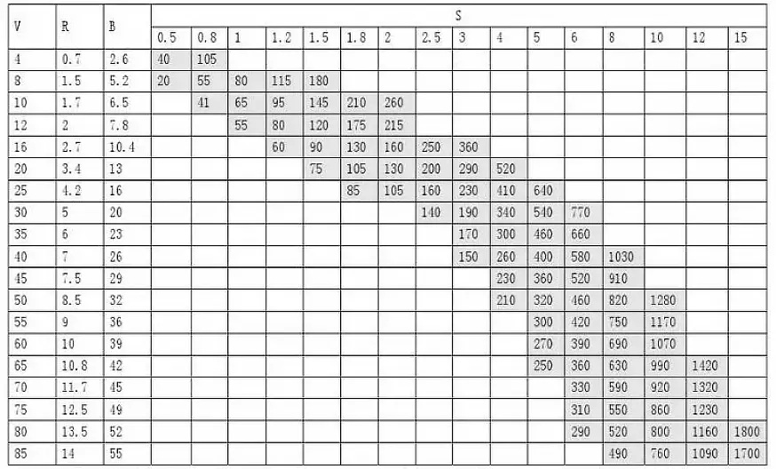
Before discussing the internal radii (R-angles) of workpieces, it’s beneficial to understand the characteristics of metal materials.
As illustrated in the stress-strain curve below, the initial portion represents the elastic deformation phase, where the material can return to its original position after the tensile force is released.
Upon continuing to apply force past the yield point, the material enters the strain-hardening phase, where further tensile force causes permanent plastic deformation. To induce greater plastic deformation, increased force is necessary.
After reaching the peak stress, further tensile force leads to necking and eventually complete fracture. During the bending process, the deformation of the sheet metal primarily occurs in the strain-hardening phase, characterized by an increased stress requirement as strain grows.
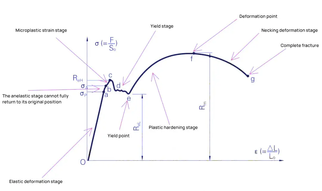
The internal R-angle of a workpiece is related to the material, as shown in the graph below.
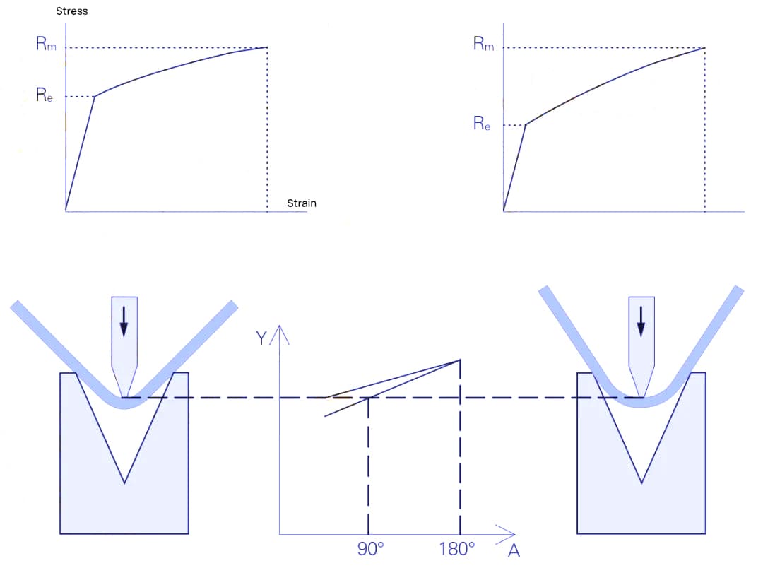
Materials with low strain-hardening have smaller internal R-angles, while those with high strain-hardening exhibit larger internal R-angles. The internal R-angle is also influenced by the die opening of the lower mold; the smaller the opening, the smaller the internal R-angle, as indicated in Table below.
Table: Relationship Between the Internal Radius of the Workpiece and the Die Opening
| Material | Bending angle | Internal R angle |
| DC01 (mild steel) | 135 ° | 0.33V |
| 90 ° | 0.17V | |
| 45 ° | 0.12V | |
| AW-5754H22 (aluminum) | 135 ° | 0.20V |
| 90 ° | 0.10V | |
| 45 ° | 0.07V | |
| X5CrNi1810 (stainless steel) | 135 ° | 0.37V |
| 90 ° | 0.20V | |
| 45 ° | 0.17V |
The selection range for the bending lower die opening is typically:
Therefore, the desired internal R-angle for a bent workpiece can be achieved by considering the material properties in conjunction with the choice of die opening.
Requirements for the upper mold: As long as the upper mold’s R-angle does not exceed the standard R-angle, it has almost no effect on the internal R-angle of the bent workpiece.
For some materials with poor ductility, a larger R-radius at the mold’s tip might also be necessary to bend a larger internal R-angle to prevent material fracture.
Sheet metal bend radius is an essential aspect to consider when fabricating or designing parts. It has a significant impact on the quality and functionality of the final product.
In this section, you’ll learn about bend radius, factors that influence it, and guidelines for selecting the appropriate minimum bend radius.
The bend radius depends on various factors, such as:
Understanding these factors and their impact on bend radius can help you make informed decisions during the design process and improve the quality and durability of your parts.
To avoid crack formation or part deformation while bending, it’s essential to adhere to minimum bend radius guidelines. These guidelines can vary based on the material and its properties:
These are general guidelines, and it’s crucial to consult material-specific recommendations or experiment with your specific sheet metal and tooling combinations to achieve the desired outcome. By adhering to appropriate bend radius guidelines, you can ensure a high-quality end product with fewer defects, less waste, and increased strength.

As the founder of MachineMFG, I have dedicated over a decade of my career to the metalworking industry. My extensive experience has allowed me to become an expert in the fields of sheet metal fabrication, machining, mechanical engineering, and machine tools for metals. I am constantly thinking, reading, and writing about these subjects, constantly striving to stay at the forefront of my field. Let my knowledge and expertise be an asset to your business.