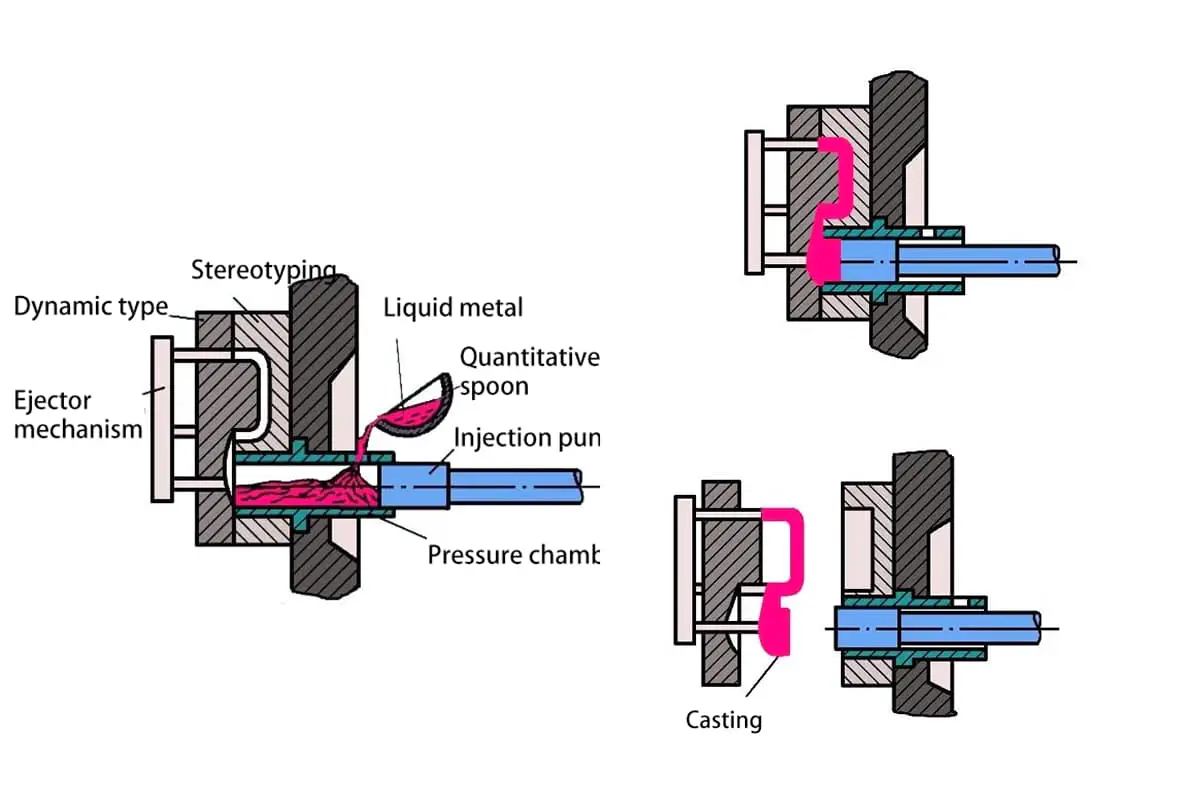
Unveiling the Secrets of the Die Casting Process: A Complete Guide
Ever wondered how your car parts are made with such precision? Dive into the fascinating world of die casting—a process where molten metal is shaped under high pressure and speed.…
Have you ever wondered how frequency converters work and why they are essential in modern electrical systems? This article dives into 40 frequently asked questions about frequency converters, shedding light on their functions, differences in modulation techniques, and practical applications. You’ll learn about their impact on motor performance, energy efficiency, and operational safety. Whether you’re a seasoned engineer or just curious, this comprehensive guide will enhance your understanding of these vital devices.
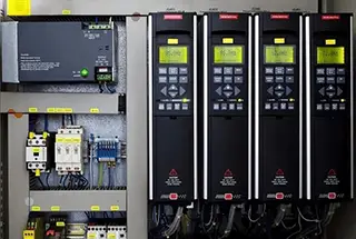
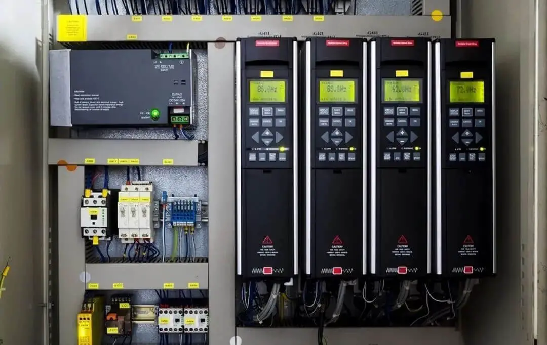
A frequency converter is an electrical device that adjusts the frequency of a power supply by using power semiconductor devices to switch on and off. It can perform several functions, including soft start, regulating frequency conversion speed, increasing operational accuracy, adjusting the power factor, and providing protection against overcurrent, overvoltage, and overload.
PWM stands for Pulse Width Modulation and is a technique for adjusting the output and waveform by changing the width of the pulses in a pulse train.
PAM stands for Pulse Amplitude Modulation and is a method of adjusting the output value and waveform by altering the amplitude of the pulses in a pulse train according to a specific law.
The main circuit of a frequency converter can be broadly classified into two types:
The voltage type frequency converter converts the DC voltage source into AC. The DC circuit filter in this type of frequency converter is a capacitor.
The current mode frequency converter, on the other hand, converts the DC current source into AC. The DC loop filter in this type of frequency converter is an inductor.
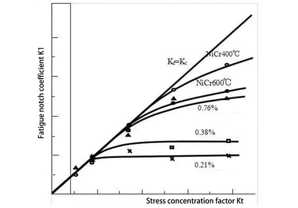
The electromagnetic torque of a motor is generated by the interaction between current and magnetic flux. It is crucial to keep the current within the rated value to avoid overheating of the motor.
If the magnetic flux decreases, the electromagnetic torque will also decrease, leading to a reduction in the load capacity of the motor.
As seen from the formula E=4.44KFNΦ, during variable frequency speed regulation, the magnetic circuit of the motor changes significantly with the operating frequency fX, which can easily cause saturation of the magnetic circuit, leading to serious distortion of the excitation current waveform and high peak current.
To avoid weak magnetic field and magnetic saturation, it is important to change frequency and voltage in proportion, i.e., control the output voltage of the frequency converter while changing the frequency to maintain a certain level of magnetic flux in the motor.
This control mode is commonly used in energy-saving frequency converters for fans and pumps.
When the frequency decreases (at low speed), if the same power output is maintained (constant power), the current will increase. However, if the condition of a certain torque is maintained (constant torque), the current remains nearly unchanged.
The frequency converter is utilized during operation by gradually increasing the frequency and voltage of the motor. The starting current is limited to less than 150% of the rated current (ranging from 125% to 200% depending on different models).
In contrast, when starting directly with a power frequency power supply, the starting current can reach 6 to 7 times the rated current, causing mechanical and electrical impact.
By using frequency converter drive, the starting process becomes smoother, with a starting current of 1.2 to 1.5 times the rated current, and a starting torque of 70% to 120% of the rated torque.
For frequency converters with automatic torque enhancement function, the starting torque exceeds 100% and allows for starting with full load.
As the frequency decreases, the voltage (V) also decreases proportionally. This relationship between V and f was previously explained in answer 4.
The proportional relationship between V and f is pre-determined based on the characteristics of the motor. Typically, several characteristic options are stored in the memory device (ROM) of the controller and can be selected through a switch or dial.
When the voltage is reduced in proportion as the frequency decreases, the ground torque generated at low speed tends to decrease as the AC impedance becomes smaller and the DC resistance remains unchanged.
To obtain a certain starting torque at low frequency, the output voltage should be increased. This compensation is known as enhanced starting.
It can be achieved through various methods, including an automatic method, selecting a V/f mode, or adjusting a potentiometer.
Although power can still be output below 6Hz, the minimum usable frequency is around 6Hz, considering factors such as motor temperature rise, starting torque, and other conditions. At this frequency, the motor can produce the rated torque without causing significant heating issues.
The actual output frequency (starting frequency) of the frequency converter varies from 0.5 to 3Hz depending on the model.
Typically, no. When the voltage is above 60Hz (there are also modes above 50Hz), it exhibits a constant power characteristic, requiring the same torque at high speed.
The motor device used is equipped with a speed detector (PG) that feeds back the actual speed to the control device for control, referred to as a “closed loop.” Conversely, a motor device without PG operation is called an “open loop.”
Most frequency converters operate in an open-loop mode, although some machines offer the option for PG feedback.
The speed sensorless closed-loop control mode calculates the actual speed of the motor using a pre-determined mathematical model and magnetic flux, effectively forming a closed-loop control with a virtual speed sensor.
In an open-loop system, even if the frequency converter outputs a specific frequency, the speed of the motor can change within the range of the rated slip rate (1% to 5%) when it is running with a load.
For applications that require high speed regulation accuracy and require the motor to operate near the specified speed even if the load changes, a frequency converter with PG feedback function can be used (as an optional feature).
The frequency converter with PG feedback function improves accuracy. However, the speed accuracy is dependent on both the accuracy of the PG and the resolution of the frequency converter’s output frequency.
If the specified acceleration time is too short and the output frequency of the frequency converter changes much more quickly than the change in speed (electric angular frequency), the frequency converter may trip and stop operating due to overcurrent, referred to as stall.
To prevent stall and ensure the motor continues running, it is necessary to monitor the current and control the frequency.
If the acceleration current becomes too high, the acceleration rate should be slowed down accordingly. The same applies during deceleration.
The combination of these actions is known as the stall function.
Acceleration and deceleration can be specified separately. This is appropriate for short-duration acceleration and slow deceleration, or for small machine tools where production beat time needs to be strictly defined.
However, for fan transmissions and other applications with long acceleration and deceleration times, the acceleration and deceleration times can be specified together.
If the command frequency of the motor is decreased during operation, the motor becomes an asynchronous generator and acts as a brake, known as regenerative (electrical) braking.
The energy generated by the motor during regenerative braking is stored in the filter capacitor of the frequency converter.
However, the regenerative braking force of a general frequency converter is limited to around 10% to 20% of the rated torque due to the relationship between the capacitor capacity and withstand voltage.
By using an optional brake unit, the regenerative braking force can be increased to 50% to 100%.
Protection functions can be divided into two categories:
(1) Automatically performs correction actions after detecting an abnormal state, such as overcurrent stall prevention and regeneration overvoltage stall prevention.
(2) Blocks the PWM control signal of the power semiconductor device after detecting an abnormality, causing the motor to stop automatically. Examples include overcurrent cutoff, regeneration overvoltage cutoff, overheating of the semiconductor cooling fan, and instantaneous power failure protection.
When a clutch is used to connect the load, the motor suddenly transitions from a no-load state to an area with a high slip rate at the moment of connection. The resulting large current flow causes the frequency converter to trip due to over-current, preventing operation.
When the motor starts, a starting current proportional to its capacity will flow, causing a voltage drop in the transformer on the stator side of the motor. If the motor has a large capacity, this voltage drop can have a significant impact.
A frequency converter connected to the same transformer may detect an undervoltage or trigger an instantaneous stop. As a result, the protection function (IPE) may activate, causing the operation to stop.
For digitally controlled frequency converters, even if the frequency command is an analog signal, the output frequency is set in increments. The smallest unit of this increment is called the frequency conversion resolution, which is typically 0.015 to 0.5Hz.
For example, if the resolution is 0.5Hz, the frequency can be changed in increments of 0.5Hz, such as from 23Hz to 23.5Hz and 24.0Hz, causing the motor to also operate in increments.
This can create issues for applications that require continuous coiling control. In such cases, a resolution of about 0.015Hz is recommended. With this resolution, a one-stage difference in a 4-stage motor is less than 1R/min, providing sufficient accuracy. Note that the specified resolution for some models may not match the actual output resolution.
The cooling effect of the frequency converter is considered in its internal and back structure design. Proper ventilation also depends on the orientation of the unit.
Therefore, it is recommended to install panel type units and wall-mounted units vertically whenever possible.
Starting a motor at very low frequency is possible, but if the specified frequency is high, it is similar to starting directly with a power frequency power supply. This will result in a large starting current (6 to 7 times the rated current), causing the frequency converter to trip due to overcurrent and preventing the motor from starting.
The following items should be taken into account when operating above 60Hz:
(1) Ensure that the machinery and devices are capable of operating at this speed, taking into account factors such as mechanical strength, noise, and vibration.
(2) When the motor reaches the constant power output range, its output torque should be sufficient to maintain operation. Note that the output power of fan, pump, and other shafts increases in proportion to the cube of speed, so be cautious when the speed increases.
(3) Consider the impact on bearing life.
(4) For motors with medium or higher capacity, especially 2-pole motors, it is important to consult with the manufacturer before operating above 60Hz.
When using a reducer, several issues should be kept in mind, depending on its structure and lubrication method.
In gear structures, a maximum limit of 70 to 80Hz should be considered.
When using oil lubrication, continuous operation at low speed can cause damage to the gear.
Basically, no. For single-phase motors with a governor switch starting type, the auxiliary winding can burn out in the speed regulation range below the operating point.
For capacitor starting or capacitor operation mode, capacitor explosions can occur.
The power supply for frequency converters is typically three-phase, but for small capacities, single-phase power supply can also be used.
The efficiency of a frequency converter depends on several factors, including the model, operating state, and frequency of use. It is difficult to provide a definitive answer.
However, it is estimated that the efficiency of frequency converters operating below 60Hz is approximately 94% to 96%. This can be used as a basis for calculating losses.
It is important to note that the power consumption may be higher when considering the loss during braking.
Designing an effective operation panel is also crucial and should be given careful attention.
Generally, the motor is cooled by an external fan installed on the shaft or by blades on the rotor end ring.
If the speed is reduced, the cooling effect will also decrease, making it unable to handle the same level of heat as it would during high-speed operation.
To prevent this, it is necessary to either reduce the load torque at low speed, use a high-capacity frequency converter in combination with the motor, or choose a special motor designed for low-speed operation.
The power source for the brake excitation circuit should be taken from the input side of the frequency converter.
If the brake engages while the frequency converter is still outputting power, it may result in an overcurrent cutoff.
To prevent this, it is important to ensure that the brake engages only after the frequency converter has stopped outputting power.
Regarding the impact of the capacitor of the frequency converter on the effective power factor after the frequency converter has been removed, steps should be taken to improve the power factor caused by the current flowing into the capacitor of the frequency converter.
Although the frequency converter is a static device, it also includes consumable components such as filter capacitors and cooling fans.
With proper maintenance, these components can be expected to have a service life of over 10 years.
For small capacity models with or without cooling fans:
For models with fans, air flows from bottom to top, so it is important not to place any mechanical equipment that could obstruct suction and exhaust at the upper and lower parts of the location where the frequency converter is installed.
Additionally, it is also important to avoid placing heat-sensitive components above the frequency converter.
In the event of a fan failure, the frequency converter is protected by either the stop detection of the electric fan or the overheat detection on the cooling fan.
For the capacitor used as a filter capacitor, its electrostatic capacity gradually decreases over time.
It is recommended to regularly measure the electrostatic capacity and assess its service life based on whether it has reached 85% of the rated capacity of the product.
Typically, the capacitor should be stored in a disc-shaped container.
However, fully enclosed disc-shaped containers can be quite large, occupy a significant amount of space, and are relatively expensive.
To address these issues, the following measures can be taken:
(1) The design of the disc should take into account the heat dissipation requirements of the device;
(2) Aluminum fins and a finned coolant can be used to increase the cooling area.
To reduce high-order harmonic interference in the input current and improve the power factor of the input power supply.
The sinusoidal filter enables the frequency converter to function with a long motor cable and is also appropriate for circuits that include an intermediate transformer between the frequency converter and the motor.
The resistance value of the potentiometer provided with the frequency converter is typically in the range of 1K Ω to 10K Ω.
(1) Radiation interference;
(2) Conducted interference.
For interference signals transmitted through radiation, they can be effectively reduced by properly routing and shielding the source of the radiation and the disturbed line.
Interference signals transmitted through the line can be addressed by adding filters, reactors, or magnetic rings on the input and output side of the frequency converter.
The specific methods and precautions for reducing interference are as follows:
(1) The signal and power lines should be crossed or bundled vertically.
(2) Avoid connecting wires made of different metals to each other.
(3) The shielding layer should be properly grounded and the grounding should be continuous and reliable along its entire length.
(4) A twisted pair shielded cable should be used in signal circuits.
(5) The grounding point for the shielding layer should be as far away from the frequency converter as possible and separate from the grounding point of the frequency converter.
(6) A magnetic ring can be used on the input power line and output line of the frequency converter.
The specific method for using a magnetic ring is as follows: The input line can be wound four times in the same direction, while the output line can be wound three times in the same direction.
It is important to keep the magnetic ring as close to the frequency converter as possible when winding.
(7) Additionally, to prevent interference, shielding and other anti-interference measures can be implemented for disturbed equipment and instruments.
The power consumed by the conveyor belt is directly proportional to its speed.
Therefore, if you wish to operate at 80Hz, the power of the frequency converter and motor must be increased proportionally, which means an increase of 60% from the 50Hz capacity. This means that the capacity of the frequency converter and motor must be increased by 60%.
In VVC (Variable Voltage and Variable Frequency) control, the control circuit utilizes a mathematical model to calculate the optimal motor excitation in response to changes in motor load and compensates for the load accordingly.
Additionally, the control circuit incorporates a synchronous 60° PWM method implemented on an ASIC (Application-Specific Integrated Circuit) which determines the optimal switching time for the inverter semiconductor devices (IGBTs).
The overall circuit of a variable frequency power supply is comprised of components such as AC constant current and AC filters, resulting in pure sine wave output voltage and current waveforms that closely resemble ideal AC power supply.
It is capable of generating grid voltage and frequency for any country in the world.
On the other hand, the frequency converter is made up of components such as AC constant current AC (modulation wave) and other circuits. The standard name for this device is a variable frequency governor.
However, the output voltage waveform of the frequency converter is a pulse square wave with numerous harmonic components. The voltage and frequency change proportionally at the same time and cannot be adjusted independently, making it unsuitable for use as a power supply.
It is typically only used for regulating the speed of a three-phase asynchronous motor.

As the founder of MachineMFG, I have dedicated over a decade of my career to the metalworking industry. My extensive experience has allowed me to become an expert in the fields of sheet metal fabrication, machining, mechanical engineering, and machine tools for metals. I am constantly thinking, reading, and writing about these subjects, constantly striving to stay at the forefront of my field. Let my knowledge and expertise be an asset to your business.