U Channel Weight Chart
Ever wondered how the weight of U channel steel affects your construction project? This article breaks down the theoretical weights of various U channel sizes, helping you choose the right…
Have you ever wondered how to select the perfect I-beam for your construction or manufacturing project? In this blog post, our expert mechanical engineer will guide you through the process of choosing the right I-beam specification and model based on your specific application. Discover the key factors to consider and unlock the secrets to optimizing your project’s success.
I-beams, also known as H-beams or W-beams, are structural steel members with an I-shaped cross-section. They are widely used in construction and manufacturing due to their excellent load-bearing capacity, high strength-to-weight ratio, and torsional stability.
Hot-rolled I-beams are produced through a controlled rolling process and come in various standard sizes, such as 8#, 10#, 12#, 14#, 16#, 18#, 20a, 20b, 22a, 22b, 25a, 25b, 28a, 28b, 30a, and 30b, to cater to different structural requirements and load conditions.
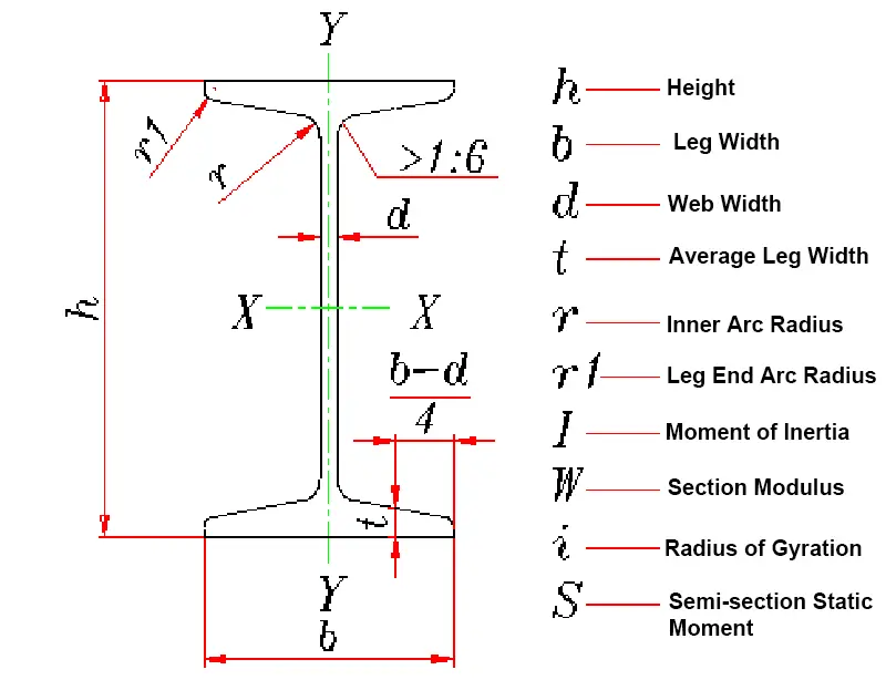
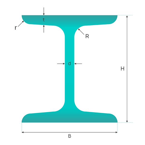
The dimensions of an I-beam are typically represented by its web height (h), flange width (b), and web thickness (d), all measured in millimeters.
For instance, an I-beam with a web height of 160mm, flange width of 88mm, and web thickness of 6mm would be denoted as “I-160x88x6”.
This standardized notation system allows for precise communication among engineers, fabricators, and suppliers.
Alternatively, I-beams can also be identified by their web height in centimeters followed by a “#” symbol, such as I-16# for the same beam, which is commonly used in quick reference scenarios.
I-beams with identical web heights may have varying web thicknesses, flange widths, and flange thicknesses to optimize performance for specific load conditions. To differentiate between these variations, letters “a”, “b”, or “c” are appended to the size designation.
For example, 32a#, 32b#, and 32c# represent I-beams with the same web height of 320mm but different cross-sectional properties. This system offers engineers flexibility in selecting the most suitable beam for their specific application, balancing factors such as load capacity, deflection limits, and material efficiency.
I-beams find extensive use in various industries due to their superior load-bearing capacity, structural stability, and versatility. In construction, they are primarily employed as primary support members in large structures such as industrial buildings, warehouses, multi-story buildings, and bridges. Their ability to resist bending moments and shear forces makes them ideal for spanning large distances.
In the manufacturing sector, I-beams play a crucial role in the production of vehicles, ships, and heavy machinery, where they serve as essential structural components, providing strength and rigidity while minimizing weight.
Additionally, I-beams are frequently used in material handling systems, such as overhead cranes and conveyor supports, due to their excellent load distribution properties and resistance to lateral-torsional buckling.
The provided chart can be used as a reference guide for the standard sizes in mm and weight of I-beams in kg.
| Spec. | Height (mm) | Flange Width (mm) | Web Thickness (mm) | Theoretical Weight (kg/m) |
|---|---|---|---|---|
| 10 | 100 | 68 | 4.5 | 11.261 |
| 12.6 | 126 | 74 | 5 | 14.223 |
| 14 | 140 | 80 | 5.5 | 16.89 |
| 16 | 160 | 88 | 6 | 20.513 |
| 18 | 180 | 94 | 6.5 | 24.143 |
| 20a | 200 | 100 | 7 | 27.929 |
| 20b | 200 | 102 | 9 | 31.069 |
| 22a | 220 | 110 | 7.5 | 33.07 |
| 22b | 220 | 112 | 9.5 | 36.524 |
| 25a | 250 | 116 | 8 | 38.105 |
| 25b | 250 | 118 | 10 | 42.03 |
| 28a | 280 | 122 | 8.5 | 43.492 |
| 28b | 280 | 124 | 10.5 | 47.888 |
| 32a | 320 | 130 | 9.5 | 52.717 |
| 32b | 320 | 132 | 11.5 | 57.741 |
| 32c | 320 | 134 | 13.5 | 62.765 |
| 36a | 360 | 136 | 10 | 60.037 |
| 36b | 360 | 138 | 12 | 65.689 |
| 36c | 360 | 140 | 14 | 71.341 |
| 40a | 400 | 142 | 10.5 | 67.598 |
| 40b | 400 | 144 | 12.5 | 73.878 |
| 40c | 400 | 146 | 14.5 | 80.158 |
| 45a | 450 | 150 | 11.5 | 80.42 |
| 45b | 450 | 152 | 13.5 | 87.485 |
| 45c | 450 | 154 | 15.5 | 94.55 |
| 50a | 500 | 158 | 12 | 93.654 |
| 50b | 500 | 160 | 14 | 101.504 |
| 50c | 500 | 162 | 16 | 109.354 |
| 56a | 560 | 166 | 12.5 | 106.316 |
| 56b | 560 | 168 | 14.5 | 115.108 |
| 56c | 560 | 170 | 16.5 | 123.9 |
| 63a | 630 | 176 | 13 | 121.407 |
| 63b | 630 | 178 | 15 | 131.298 |
| 63c | 630 | 180 | 17 | 141.189 |
| Spec. | Height (mm) | Flange Width (mm) | Web Thickness (mm) | Theoretical Weight (kg/m) |
|---|---|---|---|---|
| 8 | 80 | 50 | 4.5 | 7.52 |
| 10 | 100 | 55 | 4.5 | 9.46 |
| 12 | 120 | 64 | 4.8 | 11.5 |
| 14 | 140 | 73 | 4.9 | 13.7 |
| 16 | 160 | 81 | 5 | 15.9 |
| 18 | 180 | 90 | 5.1 | 18.4 |
| 18a | 180 | 100 | 5.1 | 19.9 |
| 20 | 200 | 100 | 5.2 | 21 |
| 20a | 200 | 110 | 5.2 | 22.7 |
| 22 | 220 | 110 | 5.4 | 24 |
| 22a | 220 | 120 | 5.4 | 25.8 |
| 24 | 240 | 115 | 5.6 | 27.3 |
| 24a | 240 | 125 | 5.6 | 29.4 |
| 27 | 270 | 125 | 6 | 31.5 |
| 27a | 270 | 135 | 6 | 33.9 |
| 30 | 300 | 135 | 6.5 | 36.5 |
| 30a | 300 | 145 | 6.5 | 39.2 |
| 33 | 330 | 140 | 7 | 42.2 |
| 36 | 360 | 145 | 7.5 | 48.6 |
| 40 | 400 | 155 | 8 | 56.1 |
| 45 | 450 | 160 | 8.6 | 65.2 |
| 50 | 500 | 170 | 9.5 | 76.8 |
| 55 | 550 | 180 | 10.3 | 89.8 |
| 60 | 600 | 190 | 11.1 | 104 |
| 65 | 650 | 200 | 12 | 120 |
| 70 | 700 | 210 | 13 | 138 |
| 70a | 700 | 210 | 15 | 158 |
| 70b | 700 | 210 | 17.5 | 184 |
I Beam Sizes Chart PDF Download:
It’s crucial to understand that the theoretical weight calculated by our tool may differ slightly from the actual weight of the I-beam. This discrepancy typically falls within a tolerance range of 0.2% to 0.7%. Several factors contribute to this variance:
For most practical applications, this small difference is negligible. However, for high-precision engineering projects, large-scale construction, or precise inventory management, it’s advisable to:
Remember to consider these factors when using the calculated weight for critical load-bearing calculations, material cost estimations, or transportation planning. Always err on the side of caution and consult with a structural engineer for projects where precise weight calculations are crucial for safety and performance.
Related reading:
The theoretical weight of I-beams made from different materials (such as Q235, Q345, etc.) varies, primarily due to their differing alloy contents. Q235 is ordinary carbon steel, while Q345 is low alloy steel. This means that Q345 contains more alloy elements than Q235, which can enhance the strength, toughness, and other properties of the steel.
Therefore, due to the difference in alloy content, the theoretical weight of Q345 is usually heavier than that of Q235.
For the calculation formula, the theoretical weight of the I-beam can be calculated using the formula W = 0.00785 [hd +2t (bd) +0.615 (r2 r12)], where W represents the theoretical weight (in kg/m), h is the height, b is the leg length, d is the waist thickness, t is the average leg thickness, r is the inner arc radius, and r1 is the end arc radius.
This formula applies to I-beams of different materials, but in actual calculations, the density value will vary due to the material difference. For example, the density of low carbon steel (like Q235) is calculated as 7.85g/cm3, while the density of stainless steel might be slightly lower.
The difference in the theoretical weight of I-beams made from different materials is primarily due to their different alloy contents. Although the specific theoretical weight needs to be determined according to the specific dimensions and material characteristics of the I-beam through the calculation formula, generally speaking, the theoretical weight of low alloy steel (like Q345) will be heavier than that of ordinary carbon steel (like Q235).
Choosing the appropriate I-beam size and model requires understanding the basic parameters and application scenarios of the I-beam. The specifications of the I-beam can be represented by its height/depth (h), width (b), and weight or mass (w). Additionally, the model of the I-beam can also be represented by the number of centimeters in the waist height, for example, I16# represents an I-beam with a waist height of 160mm.
In different application scenarios, such as construction and mechanical manufacturing, the selection of I-beams also needs to consider its mechanical properties and size range. For instance, the weight of the 18# national standard I-beam should be between 39.2-79.5kg/m with a size range of 100-400mm, suitable for scenarios requiring larger bearing capacity and a certain length. The model standards of European standard I-beams are mainly distinguished based on their cross-sectional sizes and belly plate heights, with common models including IPE80, IPE100, etc., suitable for scenarios with specific shape and size requirements.
For cantilever structures, the selection of I-beams also needs to consider thickness as it directly impacts the stability and safety of the cantilever structure. Furthermore, the selection of I-beams must comply with relevant national standards and regulations to ensure their safe and reliable performance.
When choosing the appropriate I-beam size and model, it’s essential to take into account the specific application scenario, the required bearing capacity, the stability of the structure, as well as the relevant standards and regulations to be complied with. For example, in building structures, you might need to choose I-beams with larger bearing capacity and specific size range, while in fields like mechanical manufacturing, the shape and size of the I-beam to fit specific design requirements might be more emphasized.
Standard I-beams are processed from regular steel, while light I-beams are made from lightweight alloys such as aluminum and magnesium. When compared to standard I-beams, light I-beams have wider flanges and thinner webs and flanges. Given the same depth, light I-beams offer better stability while ensuring the same load-bearing capacity, thus saving metal and providing better economic efficiency.
Regardless of whether they are standard or light, I-beams tend to have relatively high and narrow cross-sectional dimensions, resulting in a significant difference in the moment of inertia about the two main axes.
Therefore, they are typically used directly for members subjected to bending within the plane of their web or as part of a lattice force member. When used individually, they can only serve as general bending members and eccentric compression members, such as secondary beams or eccentric columns in work platforms.
However, when used as composite sections, they can function as the main compression members.
I-beams come in standard and light varieties.
Compared to the same model of standard I-beam, light I-beams have a smaller thickness and lighter weight. The flange width varies with the model size: smaller models (I32# and below) have narrower flange widths than standard I-beams, while larger models (I40# and above) have wider flange widths.

As the founder of MachineMFG, I have dedicated over a decade of my career to the metalworking industry. My extensive experience has allowed me to become an expert in the fields of sheet metal fabrication, machining, mechanical engineering, and machine tools for metals. I am constantly thinking, reading, and writing about these subjects, constantly striving to stay at the forefront of my field. Let my knowledge and expertise be an asset to your business.