Bending Strength Calculation of Section Steel: A Comprehensive Guide
How does a steel beam withstand the weight of a bridge or the pressure from a crane? This article delves into the bending strength calculations of section steel, explaining the concepts of elastic, elastic-plastic, and plastic stages. By understanding the strength and stiffness of different sections, readers will learn how to ensure the safety and stability of structures under various loads. Dive in to grasp the fundamental principles that keep our constructions standing tall and resilient.
Supports lateral loads such as floor beams, crane beams, purlins, bridges, etc.
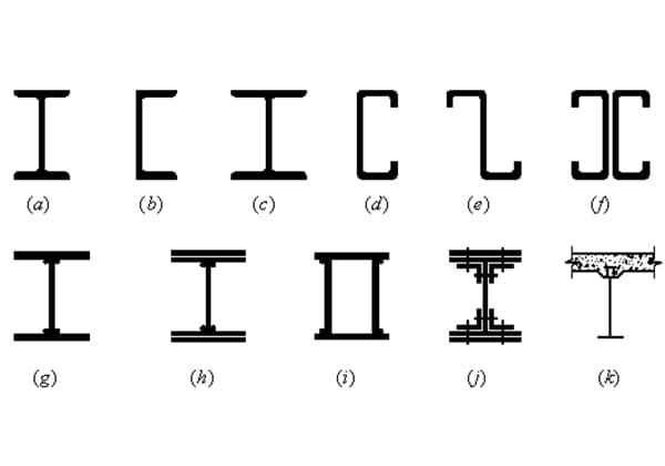
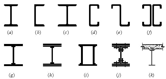
2. Classification:
(1) Solid web:
H-shaped steel section: Easy to process, simple to manufacture, and low cost.
Composite section: When the H-shaped steel cannot meet the requirements of strength and stiffness.
(2) Lattice structure:
When the span exceeds 40m, it is best to use a lattice truss.
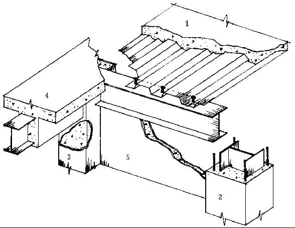
3. Beam grid:
A planar system composed of main and secondary beams that intersect vertically and horizontally.
(1) Simplified beam grid: Single main beam.
(2) Ordinary beam grid: Divided into main and secondary beams.
(3) Compound beam grid: Divided into main beams, horizontal and vertical secondary beams.
4. Interaction between beams and plates:
(1) Co-working: Composite floor slab.
(2) Non-cooperative work: General reinforced concrete slab.
Chapter Two: Bending Strength.
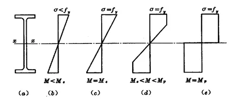
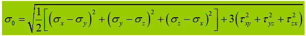
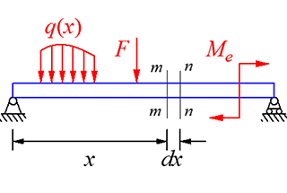
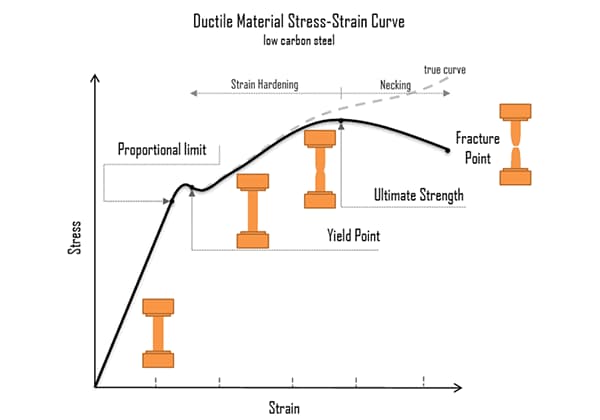
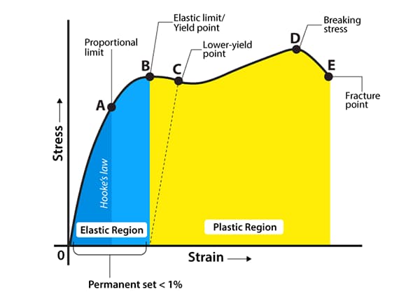
Development of normal stress in the cross-section can be divided into three stages:
(1) Elastic stage: Under dynamic load.
(2) Elastic-plastic stage: Under static load or indirect dynamic load.
(3) Plastic stage:
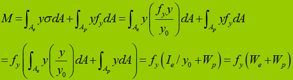
Bending capacity during the elastic-plastic stage of a cross-section:
For a rectangular section:
(1) Elastic stage:
(2) Plastic stage:
(3) Elastic-plastic stage:
Section shape factor:
Chapter Three: Strength Calculation Formulas Adopted by Codes.
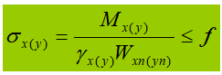
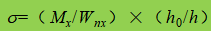
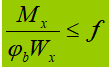
I. Bending normal stress:
Partial section plastic development (1/4 section, a = h/8) as limit state:
In the formula:
γ is the partial safety factor for the moment, which can be determined based on Table 5.1 in Section 5 of the design code.
There are two cases where the partial safety factor for moment should be taken as 1.0.
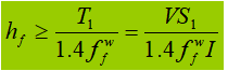
II. Shear strength:
Method:
S:
The shear strength can be calculated using the shear flow theory, assuming that it is uniformly distributed along the thickness direction of the thin wall.
(1) When calculating the vertical shear stress at any point on the web, it is necessary to calculate the area moment of inertia of the gross section above or below that point with respect to the neutral axis x.
(2) When calculating the horizontal shear stress at any point on the flange, it is necessary to calculate the area moment of inertia of the gross section to the left or right of that point with respect to the neutral axis x.
Where tw is the thickness of the section at the location where the shear stress is being calculated.
III. Local buckling stress of the web:
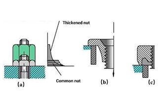
Mobile centralized crane wheel press
Fixed central load (support reaction force).
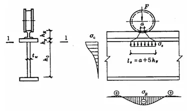
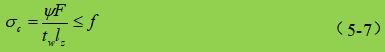
When the flange of a beam is subjected to a large fixed central load (including support reactions) and no stiffeners are provided in accordance with Figure 5-5 (a), or when it is subjected to a mobile concentrated load (such as crane wheel pressure) according to Figure 5-5 (b), the local compressive strength at the edge of the web height should be calculated. Assuming that the concentrated load spreads from the point of application to a height range of hy at a ratio of 1:2.5, and spreads at a ratio of 1:1 within a height range of hR, it is uniformly distributed over the height of the web edge calculation. The resulting σc is very close to the maximum theoretical local pressure. The local compressive strength can be calculated by the following formula:
In the formula,
F – concentrated load, which should be multiplied by the dynamic coefficient for dynamic loads;
ψ – the concentrated load amplification factor. For heavy-duty working-level crane wheel pressure, ψ = 1.35; for other loads, ψ = 1.0;
lz – the assumed distribution length of a concentrated load at the calculated height of the web plate. For a concentrated load at mid-span, lz=a+5hy+2hR; for beam end support reaction force, lz=a+2.5hy+a1;
a – the bearing length of a concentrated load along the span direction. For crane wheel pressure, when there is no data available, it can be taken as 50mm;
hy – the distance from the top of the beam to the calculated height of the web plate;
hR – the height of the track. If there is no track on the top of the beam, hR=0;
a1 – the distance from the end of the beam to the outer edge of the support plate, and its value should not be greater than 2.5hy.
When the calculation is not satisfactory, the bearing fixed concentrated load or support can be strengthened by setting transverse stiffeners or modifying the section size. However, when bearing moving concentrated loads, only the section size can be modified.
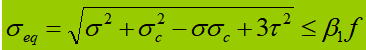
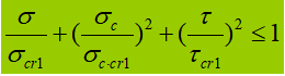
IV. Equivalent stress under complex stress state.
When the abdomen vibrator is subjected to significant normal stress, shear stress, or local compressive stress at the calculated height, the equivalent stress at that location needs to be calculated.
In the formula:
σ, τ, σc – bending normal stress, shear stress, and local compressive stress at the same point of the abdomen plate calculation height, positive for tensile stress and negative for compressive stress;
β1 – coefficient for increasing design value of compressive strength at a local point. When σ and σc have the same sign or σc=0, β1=1.1; when σ and σc have opposite signs, β1=1.2.
Section Four: Overall Stability Calculation of Beams
1. Basic Concepts
Overall instability phenomenon:
Mechanism analysis:
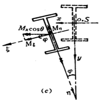
After the beam is deformed by bending, the upper flange is subjected to compression. Due to insufficient lateral stiffness of the beam, the beam will experience a lateral buckling deformation. The bending deformation in the plane caused by moment also occurs along with torsional deformation due to unequal bending from top to bottom of the beam section.
Therefore, the overall instability of the beam takes on the form of flexural-torsional buckling, or more accurately, lateral-bending and torsional buckling.
2. Calculation Formula for Critical Bending Moment of Simply Supported Beam with Uniaxial Symmetric Cross-Section:
(1) C1, C2, C3 – Related to load type
(2) Iy, Iw, It – Moment of inertia of the cross-section
(3) L – Unbraced length in lateral direction
(4) a – Location of the point of action in the height direction.
(5)
Load condition
Coefficient
G
C2
G
Mid-span concentrated load
1.35
0.55
0.41
Uniformly distributed load over the full span
1.13
0.46
0.53
Pure bending
1.00
0.00
1.00
The main factors affecting the overall stability of steel beams are:
(1) The unbraced length in the lateral direction or the distance L1 between the lateral support point of the compressed flange. The smaller the value of L1, the better the overall stability of the beam and the higher the critical bending moment.
(2) The size of the cross-section, including various moments of inertia. The larger the moment of inertia, the better the overall stability of the beam. In particular, increasing the width of the compressed flange b1 can also increase the value of βy in the formula.
(3) The constraints on the section by the end supports of the beam. If the constraints on the rotation around the y-axis of the section can be improved, the overall stability of the beam will be greatly improved.
(4) Loading type: Pure bending, uniformly distributed load, concentrated load at mid-span.
(5) The location of the point of action of the load along the height direction of the cross-section, a value; negative for the upper flange and positive for the lower flange.
3. Verification of Overall Stability
Single-plane bending:
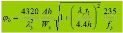
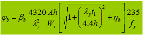
4. Overall Stability Coefficient
1. Welded I-shaped cross-section, biaxially symmetric, pure bending load.
2. Welded I-shaped cross-section, uniaxially symmetric (effects of asymmetric cross-section and different loads)
5. A double-axis symmetric I-shaped cantilever beam.
5. Ensure overall stability.
The compressed flange of the beam is covered with a decking (reinforced concrete or steel plate) and firmly connected to prevent lateral displacement of the compressed flange.
For simply supported H-beams or I-beams, the ratio of the free length L1 to the width b of the compressed flange does not exceed the value specified in Table 5.4.
Table 5.4: Maximum value of L1/b1 for which overall stability calculation is not required for simply supported H-beams or I-beams.
Steel grade
A beam without lateral support points at midspan.
A beam with a flange subjected to compression across the span and with lateral support points, regardless of where the load is applied.
1. Determine whether overall stability verification is required.
2. Calculate the section parameters.
3.Obtain the equivalent critical bending moment coefficient βb according to the load conditions.
4. Substitute the values into the formulas to obtain the overall stability coefficient ϕb, and verify the overall stability.
Example: 5-2,5-3
Section 5 – Local stability and stiffener design of beams
1. Overview:
Flange Plate: The load is relatively simple, and the local stability is ensured by limiting the width-to-thickness ratio of plate.
Web Plate: The load is complex and in order to meet strength requirements, the section height is often large. If we continue to limit the height-to-thickness ratio of the web plate, the value of the web plate will be very large which is uneconomical. Therefore, stiffeners are generally used to reduce the size of the plate and improve the local stability bearing capacity.
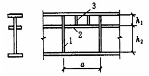
1. Transverse stiffeners
2. Longitudinal stiffeners
3. Short stiffeners
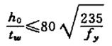
2. Local stability of wing flange plate.
Design principle: Equal strength principle.
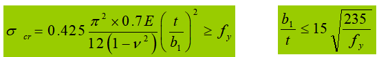
According to elastic design (with γ=1.0 for not considering plastic development), due to the influence of residual stress, the actual cross-section has entered the elastic-plastic stage. The “Specification” takes Et=0.7E.
If plastic development is considered (γ > 1.0), the plastic development will be greater, and Et=0.5E.
3. Buckling of web plate
No.
The condition of the web plate.
Stiffener arrangement specifications
1
στ=0
Stiffeners can be omitted.
2
στ≠0
It is recommended to install transverse stiffeners that meet the structural and calculation requirements.
3
It is recommended to install transverse stiffeners that meet the structural and calculation requirements.
4
The compressed flange is restrained against twisting.
Longitudinal stiffeners should be added in the compression zone of the section where bending stress is high, meeting the structural and calculation requirements.
5
The compressed flange is free to twist.
6
When necessary for calculation purposes.
7
When local compressive stress is high.
If necessary, short stiffeners should be arranged in the compression zone to meet the structural and calculation requirements.
8
At the beam support
It is advisable to install supporting stiffeners that meet the structural and calculation requirements.
9
Where the flange is subjected to a large fixed concentrated load.
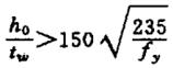
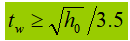
10
In any case
h0/tw should not exceed
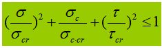
1. Buckling of composite stressed plates
Only the web plate with transverse stiffeners is configured.
The web plate is configured with both transverse and longitudinal stiffeners at the same time.
(1) Between compressed flange and longitudinal stiffeners.
(2) Between tension flange and longitudinal stiffeners.
Short transverse stiffeners are installed between the compressed flange and longitudinal stiffeners.
2. Construction requirements of stiffeners for web plate
(1) Steel transverse stiffeners configured in pairs on both sides of the web plate.
Outward protruding width:
Thickness:
(2) Steel transverse stiffeners configured on one side of the web plate.
Outward protruding width: should be greater than 1.2 times the value calculated according to the above formula.
Thickness: should not be less than 1/15 of its outward protruding width.
(3) In the web plate reinforced with both transverse and longitudinal stiffeners, the longitudinal stiffeners should be disconnected at their intersections while the transverse stiffeners remain continuous.
The moment of inertia around the z-axis should also satisfy:
(4) Treatment of the end of transverse stiffeners:
3. Stiffeners for support
(1) Stability calculation:
The stability of the stiffeners for support is calculated as a compression member subjected to fixed concentrated loads or beam support reactions along its axis. The cross-sectional area A of this compression member includes both the stiffener and the web plate area within 15tw on each side of the stiffener. The calculation length is approximately taken as h0.
(2) Compressive strength calculation:
The end of the support stiffeners for beam should be calculated according to the fixed concentrated load or support reaction that they bear. When the end of the stiffeners is trimmed flat and tight, the compressive stress on the end face should be calculated as follows:
where:
fce is the strength design value of steel end face compression;
Ace is the area where the support stiffeners contact the flange plate or column cap.
Design steps for web plate transverse stiffeners:
1. Determine if cross bars are necessary to be installed;
2. Install the crossbars and determine the spacing a, bs, ts;
3. Verify the composite stress state of the web plate;
4. Verify the supporting stiffener: including the weld (connection between the crossbars and the web plate), axial compression stability verification (stabilization outside of the z-axis plane), and strength verification.
Example 5-3: Based on the conditions and results in Example 5-2, verify whether the main beam section shown in Figure 5-9(b) meets the requirements. The main beam is a simply supported beam at both ends, made of Q235 steel and welded with E43 series manual welding electrodes.
Solution:
1. Load bearing capacity of the main beam:
The simplified calculation diagram of the main beam is shown in Figure 5-9(a). The pressure exerted on the main beam by the secondary beams on both sides is 2×73.69+2×2.33=152.04 kN, and the pressure of the secondary beams at the end of the beam is half of that of the middle secondary beam.
Figure 5-9. Simplified calculation diagram of main beam.
The support reaction of the main beam is R=2×152.04=304.08 kN.
The maximum bending moment of the beam is M=(304.08-76.02)x5-152.04×2.5=760.2 kN.m
2. Calculate the section characteristics:
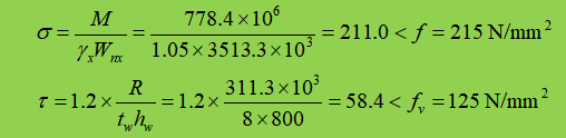
A=131.2 cm², Ix=145449 cm⁴, Wx=3513.3 cm³. The self-weight of the main beam is 131.2×10²x7850x10⁻⁶x1.2=123.6 kg/m=1.211 kN/m. The factor of 1.2 is to consider the increased coefficient of the main beam stiffener. The design value of the bending moment after considering the weight of the main beam is M=760.2+1.2×1.211×10²/8=760.2+18.2=778.4 kN·m.
Considering the design value of reaction force on the support after accounting for the self-weight of the main beam is R=304.08+1.2×1.211×10/2=304.08+7.27=311.3kN.
3. Strength check
Supporting stiffeners are provided at the connection of the secondary beam, and there is no local compressive stress. Additionally, since the shear stress is relatively small, there is no need to verify other section converted stresses.
4. There is a rigid plate on the secondary beam, which ensures the stability of the secondary beam and can serve as a lateral support point for the main beam.
At this point, since l1/b1=2500/240=10.4<16, overall stability can be ensured without calculation.
5. Stiffness check
The total standard value of the load transmitted by the secondary beam is FT=(15.5+0.52)×7.5=120.2kN, therefore,
The total standard value of load transmitted by the secondary beam is FQ=2.5×4.2×7.5=78.75kN, therefore,
6. Local stability
Flange: b/t=(120-4)/14=8.3<13, which meets the requirement of local stability, and γx can be taken as 1.05; Web plate: h0/tw=800/8=100, transverse stiffeners need to be provided, details are omitted.
Section 6. Strength after Buckling of Thin Plates
1. The concept and analysis of strength after buckling of thin plates:
After the thin plate buckles, transverse tensile stresses are generated in the middle of the plate, which further restricts the longitudinal bending deformation of the plate, enabling it to continue to withstand increased pressure.
2. Analysis of Shear Bearing Capacity of Web Plate Considering Strength after Buckling:
1. Shear bearing capacity after buckling: Formula (5-94)
2. Shear bearing capacity includes two parts: Buckling shear force (buckling strength) + tension field shear force (strength after buckling).
3. Tension field shear force:
(1) Tension field method (complex);
(2) Code specification.
3. Analysis of Bending Bearing Capacity of Web Plate Considering Strength after Buckling:
Considering that the bending bearing capacity of the web plate decreases slightly after buckling.
Two assumptions:
(1) Effective height;
(2) Symmetry between the tension zone and compression zone.
The formula for calculating the bearing capacity:
4. Calculation formula for beams considering strength after buckling (simultaneously subjected to bending moment and shear force):
In the formula,
M and V are the design values of bending moment and shear force on the same cross-section of the beam
When V < 0.5Vu, take V=0.5Vu
When M < Mf, take M = Mf
This indicates that:
(1) When M on the section is less than Mf that the flange can withstand, the web plate can bear the shear force Vu;
(2) When V on the section is less than 0.5Vu, take M = Meu.
5. Design of Transverse Stiffeners Considering Post-Buckling Strength
(1) If supporting stiffeners alone cannot satisfy Equation (5.99), paired transverse stiffeners should be added on both sides of the web to reduce the length of the buckling region.
(2) The cross-sectional dimensions of the transverse stiffeners should meet the construction requirements for the web stiffeners as per Equation 5.85.
(3) According to the steel structure specifications, the central transverse stiffener should be treated as an axial compression member and its stability outside the plane of the web should be calculated based on axial force using the following formula:
When the stiffener is subjected to a concentrated transverse load F, Ns should be increased by F.
Section 7. Design of Steel Beams
1. Design of Rolled Steel Beams
Calculate the design value of the maximum bending moment Mmax for the beam based on actual conditions.
Determine the required section modulus based on bending strength and overall stability:
Determine the steel section based on the section tables.
Verification of the section:
(1) Strength verification: bending, shear, local compression, and equivalent stress.
(2) Stiffness verification: verify the deflection-to-span ratio of the beam.
(3) Overall stability verification (local stability of the steel section usually does not require verification).
(4) Adjust the section based on the verification results, and perform verification again until it meets the design requirements.
2. Section Design of Composite Beams
1) Determine the required section modulus based on the load conditions.
2) Determine the beam height:
Minimum height: hmin is determined by the beam stiffness.
Maximum height: hmax is determined by the architectural design requirements.
Economical height: he is determined by the minimum steel consumption.
Selected height: hmin ≤ h ≤ hmax.
3). Determine the thickness of the web (assuming that all shear forces are borne by the web), then:
Alternatively, the web thickness can be determined using empirical formulas:
4). Determine the flange width:
After determining the web thickness, the flange area Af can be determined based on bending strength requirements. Taking an I-shaped section as an example:
Once Af is determined, either b or t can be selected to determine the other value.
5). Verification of the section:
Strength verification: bending, shear, local compression, and equivalent stress strength.
Stiffness verification: verify the deflection-to-span ratio of the beam.
Overall stability verification.
Local stability verification (flange plate).
Adjust the section based on the verification results, and perform verification again until it meets the design requirements.
Calculate and arrange stiffeners according to actual conditions.
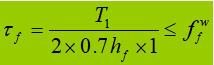
6). Calculation of Welds between Web and Flange
The connection weld is mainly used to resist bending shear, and the shear per unit length is:
When the beam is subjected to a fixed concentrated load without support stiffeners, the upper flange weld bears both shear force T1 and concentrated force F. The force per unit length generated by F is V1:
3. Change of Section for Welded Composite Beams
Purpose: To save steel and to deal with changes in bending moment.
Methods of section change:
Change the flange width.
Change the flange thickness or number of layers.
Change the web height and thickness.
Points to note:
This method is only used for long spans.
The section change should be gradual to prevent severe stress concentration.
The equivalent stress should be verified.
Section 8. Splicing of Steel Beams
1. Classification: factory splicing and on-site splicing.
2. Rolled steel sections: butt welding and splice plate welding.
3. In composite beam splicing: The web and flanges are staggered in factory splicing. The web and flanges are spliced on the same section in on-site splicing.
Points to note:
All splices should be arranged where the bending stress is relatively small.
It is difficult to ensure the quality of on-site welding.
Section 9. Connection of Primary and Secondary Steel Beams and Beam Supports
1. Connection of primary and secondary steel beams: overlap and butt joint.
As the founder of MachineMFG, I have dedicated over a decade of my career to the metalworking industry. My extensive experience has allowed me to become an expert in the fields of sheet metal fabrication, machining, mechanical engineering, and machine tools for metals. I am constantly thinking, reading, and writing about these subjects, constantly striving to stay at the forefront of my field. Let my knowledge and expertise be an asset to your business.
How do engineers ensure the strength and durability of beams under various loads? This article dives into the principles of bending shear stress and the conditions needed to maintain beam…
Have you ever wondered why some metal parts fail unexpectedly? Fatigue strength, a critical factor in mechanical engineering, holds the answer. In this insightful article, we delve into the fascinating…
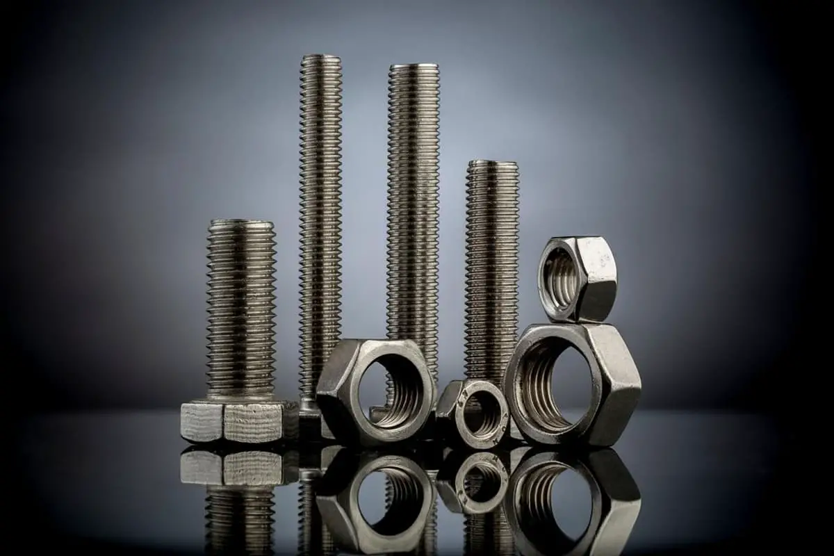
How can we make bolts last longer under stress? This article explores methods to boost the fatigue strength of bolts, essential for preventing failures in high-stress environments like engines. Learn…
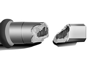
Why do high-strength bolts fail during manufacturing? This article dives into the investigation of fractured high-strength bolts, revealing that casting defects and improper hot forging are the culprits. By examining…
What makes some metal components last while others fail? Fatigue strength is key, influenced by factors like stress concentration, material quality, and environmental conditions. This article explores these critical elements,…
What makes one material bend while another breaks under the same load? The difference lies in their strength and stiffness. This article explores these crucial properties, defining strength as a…
1. Experimental Materials 1.1 Material Performance Parameters The experiment studied DP590 high-strength steel, whose chemical composition is shown in Table 1, and performance parameters are shown in Table 2. Table…
How can you ensure your bolted connections are both strong and reliable? This article delves into practical techniques to enhance bolt strength, covering crucial areas like load distribution, stress reduction,…
Yield strength, a crucial yet often overlooked property, plays a vital role in materials selection. In this article, we'll delve into the fundamentals of yield strength and explore its significance…