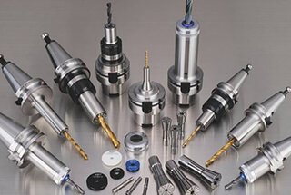
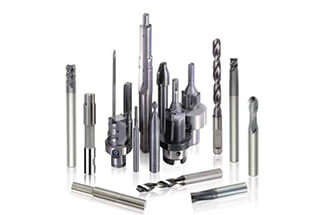
Have you ever wondered what the secret is behind high-precision machining? In this blog post, we’ll dive into the world of tool holders, exploring their types, features, and best practices. Our expert mechanical engineer will guide you through the intricacies of tool holders, helping you understand how they impact machining accuracy and efficiency. Get ready to learn valuable insights that can take your machining skills to the next level!
According to the taper of the tool hole of the machining center spindle, it is usually divided into two categories:
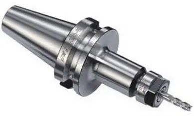
SK universal tool holder with a taper of 7:24
HSK vacuum tool holder with a taper of 1:10
SK universal tool holder with a taper of 7:24
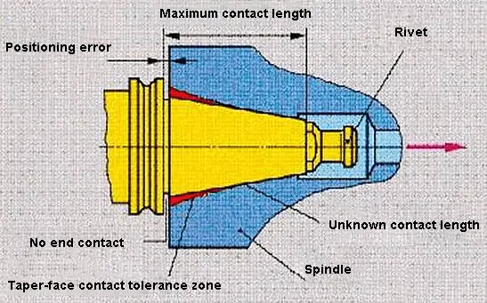
7:24 means that the taper of the tool holder is 7:24, which is a single taper surface positioning with a longer taper shank.
The tapered surface serves two important functions at the same time, which are the precise positioning of the tool holder relative to the spindle and the clamping of the tool holder.
Advantages:
The non-self-locking design allows for quick tool loading and unloading. The cost of the tool holder is relatively low since the taper angle can be machined to a high degree of accuracy, ensuring a precise connection.
Disadvantages:
During high-speed rotation, the tapered hole at the front end of the spindle will expand. The amount of expansion increases with the increase in rotation radius and speed, which decreases the taper connection rigidity. The axial displacement of the tool holder will also change under the action of the drawbar tension. After each tool change, the radial dimension of the to
There are usually five standards and specifications for universal tool holders with a taper of 7:24:
HSK vacuum tool holder with a taper of 1:10
International Standard: IS0 7388/1 (abbreviated as IV or IT)
Japanese standard: MAS BT (abbreviated as BT)
German standard: DIN 2080 type (abbreviated as NT or ST)
American Standard: ANSI/ASME (abbreviated as CAT)
DIN 69871 type (abbreviated as JT, DIN, DAT or DV)
Tensioning Method.
Type NT tool holders are tightened by a drawbar on conventional machines, which is also known domestically as ST.
The other four tool holders are tightened on the machining center through a spigot at the end of the tool holder.
Universality.
(1) At present, the most widely used tool holders in China are DIN 69871 (JT) and Japanese MAS BT.
2) DIN 69871 tool holders can also be mounted on machines with ANSI/ASME spindle taper bores.
(3) The international standard IS0 7388/1 tool holder can also be installed on DIN 69871, ANSI/ASME spindle tapered bore machine tools. So in terms of versatility, the IS0 7388/1 tool holder is the best.
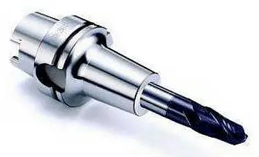
HSK vacuum tool holders with a taper of 1: 10
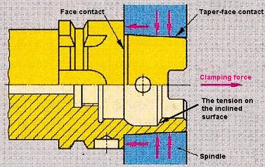
HSK vacuum tool holders rely on the elastic deformation of the tool holder, not only the tool holder with a taper of 1: 10 in contact with the 1:10 taper of the machine tool spindle bore, but also the flange face of the tool holder is in close contact with the spindle face.
This double-sided contact system is superior to a 7:24 universal tool holder in terms of high-speed machining, connection rigidity and overlap accuracy.
The HSK vacuum tool holder can improve the rigidity, stability, and product accuracy during high-speed machining, and also shorten the time of tool replacement, which is essential for high-speed machining. It is suitable for machine tool spindle speeds of up to 60,000 rpm. The HSK tool system is being widely used in the aerospace, automotive, and precision mold industries, among others.
HSK tool holders are available in types A, B, C, D, E, and F, with types A, E, and F being commonly used on machining centers with an automatic tool change (ATC) process.
The biggest difference between Type A and Type E:
(1) Type A has a transmission groove, but Type E does not. Therefore, Type A has a relatively larger transfer torque, which can handle heavy cutting. The torque transmitted by Type E is relatively small, so it can only handle light cutting.
(2) Type A tool holder has manual fixing holes and direction grooves, in addition to the transmission groove, resulting in relatively poor balance. Type E does not have these features, making it more suitable for high-speed processing.
The mechanisms of Type E and Type F are identical. The difference between them is that for handles with the same name (such as E63 and F63), the taper of the Type F handle is one size smaller. This means that both E63 and F63 have a flange diameter of φ63, but the F63 taper is only the same size as the E50. Therefore, the F63 will rotate faster (with a smaller spindle bearing) compared to the E63.
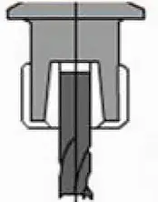
Tool Clamping Form of the Tool Holder
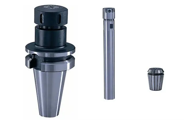
Spring cartridge tool holder
It is mainly used for straight tool holders such as drills, milling cutters and taps, or tool clamping.
The elastic deformation of the circlip is 1mm, and the clamping range is 0.5~32mm in diameter.
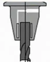
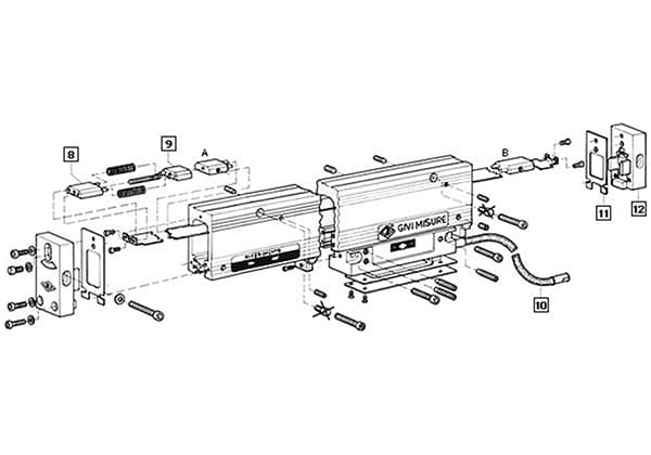
Hydraulic chuck
A- Locking screw, which use an Allen key to tighten the locking screw;
B- Locking piston, which presses the hydraulic medium into the expansion chamber;
C- Expansion chamber, which pressurized by liquid to generate pressure;
D-Thin expansion bushing, which enables the center of the tool clamping rod to be positioned and evenly enveloped during the locking process.
E- Special seals, which ensure ideal sealing and long service life.
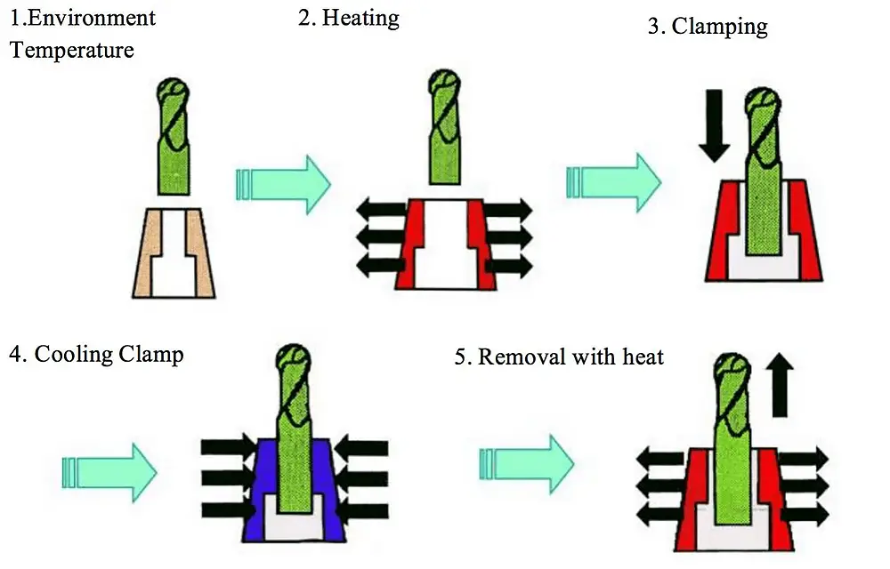
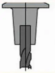
Heated tool holder
Sensing heating technology is used to heat the tool clamping part of the tool holder, causing it to expand in diameter. The cold shank is then inserted into the hot tool holder. This results in a high clamping force and good dynamic balance, making it suitable for high-speed machining.
The technology also provides high repeatability accuracy within 2μm and radial runout within 5μm, and has good resistance to stains and interference during machining.
However, only one tool of a specific shank diameter can be installed for each tool holder specification, and a set of heating equipment is also required.
The principle of pyrocondensational tool holder clamping:
Comprehensive evaluation and comparison of tool holders
Evaluation
Spring clamp type
Hydraulic type
Pyrocondensational type
Structure Diagram
Versatility
be used in all processes; highly versatile
limited for high-speed machining; high maintenance costs
excellent performance in a wide range of high-speed machining applications
Toolholder beating
quality spring clip <10µm
>5µm
about 3µm
Rigid
good
good
Dynamic Equilibrium
good
general
good
Vibrations
no advantage
can absorb vibrations
no advantage
Convenience
accuracy depends on the operator
clamping structure is easily damaged
standardized operation
Cost
general
expensive
Cheaper than Hydraulic type
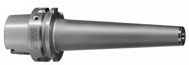
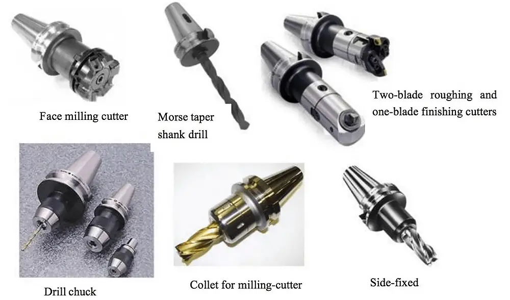
Other types of tool holders
Tool Holder Selection and Maintenance
Factors Influencing Selection
When choosing a tool holder, several key factors should be considered to ensure optimal performance and compatibility with your machinery:
Compatibility: Ensure that the tool holder fits your machine spindle. This involves checking the taper size and type (e.g., CAT, BT, HSK) to match your machine’s specifications.
Tool Type and Size: Select the appropriate holder for the specific tool required. Consider the tool’s diameter, length, and the type of machining operation (e.g., milling, drilling, turning).
Material: The material of the tool holder affects its durability and performance. Common materials include:
Steel: Offers high strength and durability, suitable for heavy-duty applications.
Aluminum: Lightweight and resistant to corrosion, ideal for high-speed applications but less durable than steel.
Plastic: Generally used for lighter applications or specific environments where metal might cause issues, but less common in industrial settings.
Balance: For high-speed applications, look for tool holders with better balance and minimum runout. Balanced tool holders reduce vibrations and improve machining accuracy and tool life.
Proper Care and Handling
To prolong the life of your tool holders and maintain their performance, follow these steps:
Storage: Store tool holders in a dry and clean environment, away from contaminants and moisture. Use designated storage racks or cabinets to prevent damage.
Cleaning: Clean tool holders with a soft cloth before and after usage to remove debris. Avoid using harsh chemicals that could damage the tool holder’s surface.
Inspection: Regularly inspect tool holders for signs of wear, damage, or corrosion. Look for any cracks, dents, or deformities. Replace tool holders if they show significant wear or damage to prevent compromising machining quality.
Lubrication: Apply lubricants as needed to prevent rust and ensure smooth operation. Use appropriate lubricants recommended by the tool holder manufacturer.
Handling: Handle tool holders with care to avoid damage. Avoid dropping them or knocking them against hard surfaces. Use protective covers or sleeves when transporting tool holders to prevent accidental damage.
By considering these factors and following proper maintenance practices, you can ensure that your tool holders remain in good condition, providing reliable and accurate performance in your machining operations.
As the founder of MachineMFG, I have dedicated over a decade of my career to the metalworking industry. My extensive experience has allowed me to become an expert in the fields of sheet metal fabrication, machining, mechanical engineering, and machine tools for metals. I am constantly thinking, reading, and writing about these subjects, constantly striving to stay at the forefront of my field. Let my knowledge and expertise be an asset to your business.
Have you ever wondered how CNC machine tools are chosen for optimal performance? In CNC machining, the selection of cutting tools is crucial for efficiency and accuracy. This article dives…
Imagine having the perfect tool for every unique challenge in mold making. From intricate free-form surfaces to high-precision requirements, selecting the right cutting tools for CNC milling can dramatically influence…
Imagine your CNC machine tool is out of alignment—just a tiny miscalculation could lead to costly mistakes. This article breaks down essential methods for accurate tool alignment in CNC milling…
Imagine a world where CNC machines can diagnose their own problems, program themselves, and achieve unprecedented levels of precision and speed. This is the future of the CNC machine tool…
What happens when a CNC machine tool malfunctions? The intricate systems of CNC machinery, which are crucial for modern manufacturing, can be daunting to repair. This article delves into the…
Ever wondered how modern factories achieve such precision and efficiency? This article explores the fascinating world of Computer Numerical Control (CNC) systems, revealing how they revolutionize manufacturing. Discover the key…
Imagine if the precision of your CNC machine could be constantly monitored, ensuring each movement is exact. This is the role of the grating ruler, acting as the machine’s "eyes."…
With the development of science and technology, mechanical manufacturing technology has undergone profound changes. Due to the stronger social demand for product diversification and the obvious increase in the proportion…
Have you ever wondered why CNC machining tools fail prematurely? Tool damage and wear can disrupt production, leading to costly delays. This article explores common issues like micro-chipping, thermal cracking,…