Have you ever wondered how a flat sheet of metal can be transformed into a complex, hollow part? Deep drawing, a fascinating forming process, makes this possible. In this article, we’ll dive into the intricacies of deep drawing, exploring its principles, challenges, and applications. Whether you’re a curious engineer or a manufacturing enthusiast, join us on this journey to uncover the secrets behind this remarkable process.
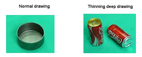
Deep drawing is a processing method that uses a drawing die to press the flat blank into various open hollow parts or process the manufactured hollow parts into other shapes of hollow parts under the pressure of a press.
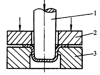
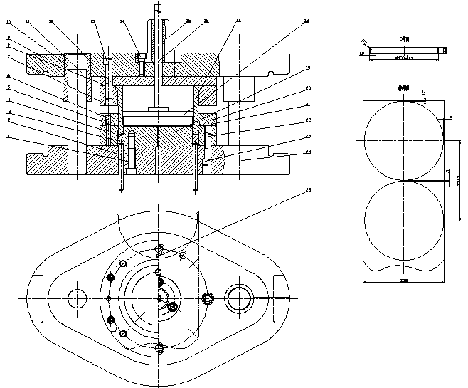
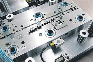
The mold for deep drawing is been called deep drawing die.
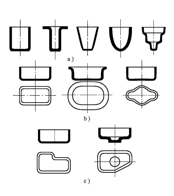
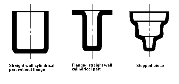
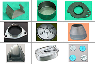
Types of deep drawing parts
a) Deep drawing of axisymmetric rotating parts
b) Box parts
c) Asymmetric drawing parts
Deep drawing parts with more complicated shape
Analysis of Deep Deformation Process
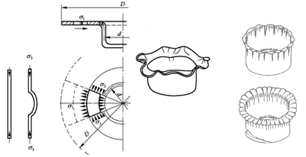
1.1 Deep deformation process and characteristics
Deep drawing is the process of plastic flow of materials
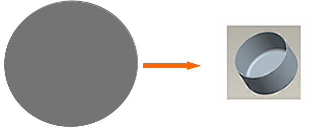
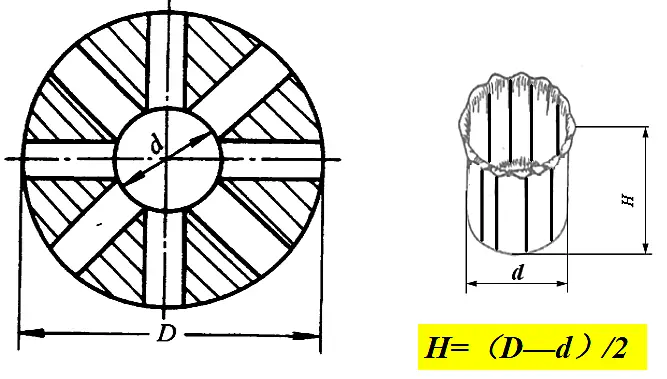
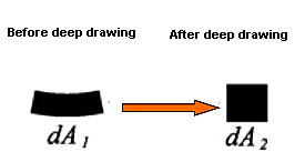
How to process a round flat blank into an open hollow part without a mold?
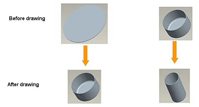
Before deep drawing:
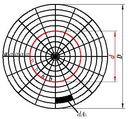
a=a=……=a
b=b=……=b
Material thickness t
After deep drawing:
a<a1<a2<a3<a4<a5
b1=b2=… …=b
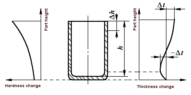
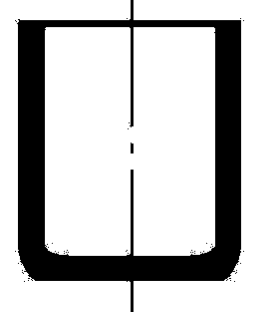
The thickness of the material varies along the height, and the mouth thickens.
h>(D—d)/2
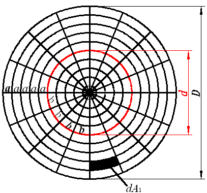
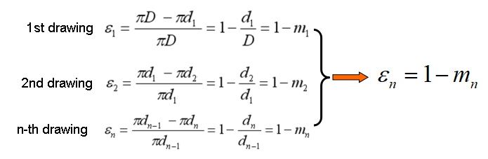
Changes before and after grid deep drawing.
Forces on the grid during deep drawing
Change of sheet thickness in height direction
Deep deformation characteristics:
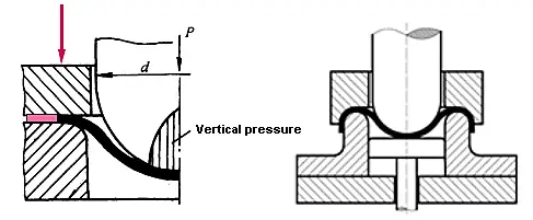
The material under the die has little change during the drawing process. The deformation is mainly concentrated in the (D-d) circular ring portion on the die plane, which is the main deformation area of the drawing.
The deformation in the deformation zone is uneven. Under the combined action of tangential compressive stress and radial tensile stress, the metal is compressed in the tangential direction, and the more it compresses at the mouth, the more it extends in the radial direction, and the more the mouth is elongated.
The thickness varies from place to place in the height direction, and the thickness at the mouth of the drawn part increases most.
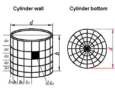
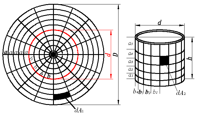
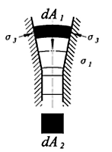
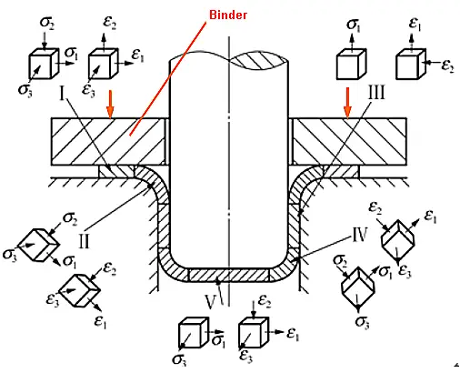
1.2 State and distribution of stress and strain of billet during deep drawing
Stress-strain state
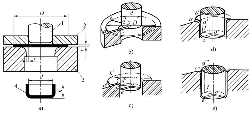
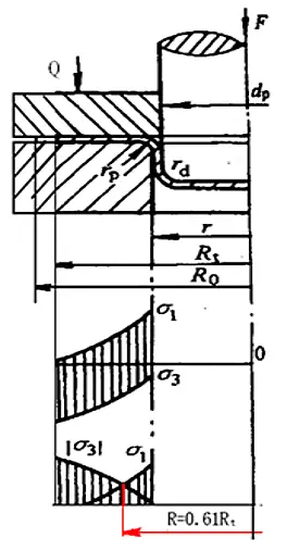
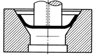
Take the first deep drawing of a straight-walled cylindrical part with a blank holder as an example.
Subscripts 1, 2, and 3 represent the radial, thick, and tangential stresses and strains of the billet, respectively.
Stress-strain distribution
1) Ignore the stress in the thickness direction and do not consider work hardening
2) Solve two unknowns from the two equations of plastic deformation condition and force equilibrium condition
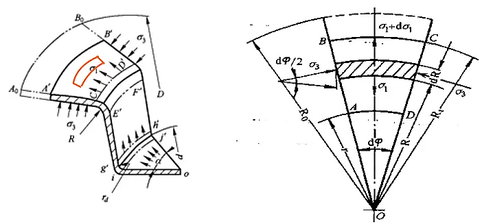
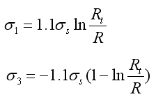
Stress in deformation zone
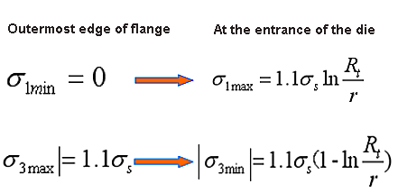
The value range of R: [r ~ Rt], σ1 and σ3 are changing every moment in the drawing process
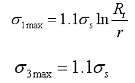
Stress σ1 and σ3 distribution in deformation zone
When Rt = 0.61R0, |σ1|=|σ3|
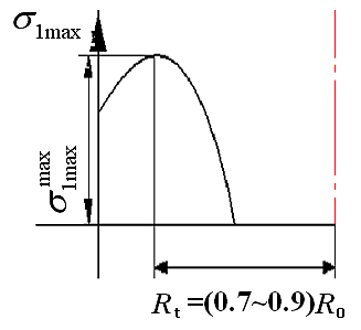
Variation of σ1max and σ3max during deep drawing
σ1max reaches the maximum value during drawing when Rt = (0.7 ~ 0.9) R0
Deep drawing quality analysis and control
The main quality issues in the drawing process:
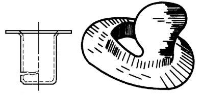
Wrinkling in the deformation area of the flange
Rupture of dangerous section
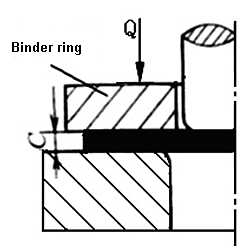
2.1 Wrinkling
The concept and cause of wrinkling
Wrinkling refers to the phenomenon that uneven wrinkles are formed in the deformation area of the flange along the tangential direction during deep drawing deformation.
Geometry of the working part of the die: conical die is not easy to wrinkle
In general: the larger the flange width, the thinner the thickness, the smaller the elastic modulus and the hardening modulus of the material, the weaker the resistance to instability, and the easier it is to wrinkle.
Measures to prevent wrinkles
The most effective measure to prevent deep wrinkling in actual production is to use a blank holder ring and apply a suitable blank holder force Q
A few important conclusions about wrinkling:
(1) Wrinkling law: It has been proved in practice that wrinkles are most likely to occur during the first drawing of a straight-walled cylindrical part: the initial stage of deep drawing
(2) Anti-wrinkle measures: use blank holder ring to apply appropriate blank holder force
(3) Wrinkling position: the main deformation area of deep drawing (flange deformation area)
2.2 Drawing breakage-the key to deepening success
The concept of drawing breakage and its causes
When the tensile stress of the cylinder wall exceeds the tensile strength of the material of the cylinder wall, the drawn part will rupture at the tangent of the bottom corner and the cylinder wall-the “dangerous section”.
Mainly depends on:
Tensile stress in the force transfer zone of the cylinder wall
Tensile strength of the tube wall force transmission zone
Factors affect drawing breakage
(1) sheet mechanical properties
(2) drawing coefficient m
(3) the corner radius of the die
(4) friction
(5) blank holder force
Measures to prevent cracking
Use materials with large hardening index and small yield ratio for deep drawing;
Properly increase the radius of the convex and concave corners of the drawing;
Increase the number of deep drawing;
Improve lubrication.
Practice proves:
In the first deep drawing of the straight-walled cylindrical part, the most likely time for the crack to occur is in the initial stage of deep drawing.
Deep drawing process calculation
3.1 Calculation of Drawing Process for Straight Wall Rotating Parts
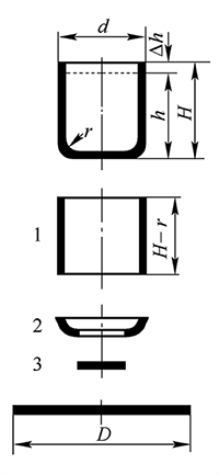
Calculation of drawing process for cylinders without flange
(1) Determination of the shape and size of the blank
The basis for determining the shape and size of the blank:
Shape similarity principle: The shape of the blank before drawing of the rotating body part is similar to the shape of the cross-section of the workpiece after drawing.
According to this, the shape of the blank used for the cylindrical part is circular
Principle of equal surface area: If the thickness of the material before and after drawing is unchanged, the surface area of the blank before drawing and after drawing are approximately equal.
Calculation steps of blank size:
1) Determine the margin for trimming.
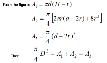
2) Calculate the surface area of the drawn part.
The deep drawing is divided into several simple geometries.
Find the surface area ofeach simple geometry.
Adding the surface area ofeach simple geometry is the total surface area of the part.
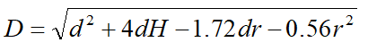
3) According to the principle of equal surface area, find the diameter of the blank.
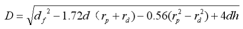
Calculation formula of blank size
1) Check the table 5-2 to get the trim margin △h
Table: Trim allowance for non-flanged parts
Deep drawing height H
Deep drawing height H/d
>0.5~0.8
>0.8~1.6
>16~2.5
>2.5~4
≤10
1
1.2
1.5
2
>10~20
1.2
1.6
2
2.5
>20~50
2
2.5
3.3
4
>50~100
3
3.8
5
6
>100~150
4
5
6.5
8
>150~200
5
6.3
8
10
>200~250
6
7.5
9
11
>250
72
8.5
10
12
2) Calculate surface area
The simplified blank diameter is:
Note: When the sheet thickness t<1mm, all dimensions are substituted with the marked dimensions, otherwise the midline dimensions are substituted.
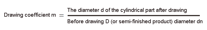
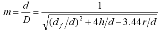
(2) Determination of drawing coefficient
1) The concept of drawing coefficient
Relationship between drawing coefficient and drawing deformation
That is, the size of m can indirectly reflect the amount of tangential deformation.
The important conclusion of the deep drawing coefficient:
The drawing coefficient can indicate the degree of drawing deformation. The smaller the drawing coefficient, the greater the drawing deformation. When the drawing coefficient is less than a certain value, the drawing part will be pulled apart, so there is a limit drawing coefficient .
Ultimate drawing coefficient [mn]: The minimum drawing coefficient that keeps the drawing from breaking.
When performing the drawing process calculation and mold design, always reduce the drawing coefficient value as much as possible in order to reduce the number of drawing times.
2) Factors affecting the limit drawing coefficient
① Material
② The relative thickness of the sheet is large, and [m] can be reduced.
③ In terms of mold (small ultimate drawing coefficient)
The overall influence law: Any factor that can increase the strength of the dangerous section of the tube wall force transmission zone and reduce the tensile stress in the tube wall force transmission zone will reduce the limit drawing coefficient, and vice versa.
3) Determination of the limit drawing coefficient
Table 5-3 and Table 5-4 are the limit drawing coefficients for each drawing of flangeless cylindrical parts.
Table: The limit stretching ratio of the cylindrical part with flanging (08, 10, 15Mn, and H62).
Deep drawing coefficient
Relative thickness t/D*100
2~1.5
1.5~1
1~0.6
0.6~0.3
0.3~0.15
0.15~0.08
m1
0.48~0.50
0.5~0.53
0.53~0.55
0.55~0.58
0.58~0.60
0.60~0.63
m2
0.73~0.75
0.75~0.76
0.76~0.78
0.78~0.79
0.79~0.80
0.80~0.82
m3
0.76~0.78
0.78~0.79
0.79~0.80
0.80~0.81
0.81~0.82
0.82~0.84
m4
0.78~0.80
0.80~0.81
0.81~0.82
0.82~0.83
0.83~0.85
0.85~0.86
m5
0.80~0.82
0.82~0.84
0.84~0.85
0.85~0.86
0.86~0.87
0.87~0.88
Table: The ultimate drawing coefficient of cylindrical parts without blank holder (08, 10 & 15Mn)
Relative thickness t/D*100
Deep drawing coefficient for each time
m1
m2
m3
m4
m5
m6
1.5
0.65
0.80
0.84
0.87
0.90
–
2.0
0.60
0.75
0.80
0.84
0.87
0.90
2.5
0.55
0.75
0.80
0.84
0.87
0.90
3.0
0.53
0.75
0.80
0.84
0.87
0.90
>3
0.50
0.70
0.75
0.78
0.82
0.85
In order to improve process stability and part quality, deep drawing coefficients slightly larger than the limit drawing coefficient [mn] should be used in actual production for deep drawing.
(3) Determination of drawing times
When [mtotal]> [m1], the drawing part can be drawn at one time, otherwise multiple drawing times are required.
There are several ways to determine the number of deep drawing:
Table lookup method (Table 5-5)
Prediction method
Calculation method
Steps to calculate the number of deep drawing methods:
1) Check the limit drawing coefficient [mn] of each time from Table 5-3 or Table 5-4.
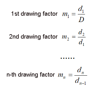
2) Calculate the ultimate diameter of each drawing in turn, that is,
d1=[m1 ]D;
d2=[m2 ]d1;
…;
dn=[mn]dn-1;
3) When dn≤d, the number of calculations n is the number of deep drawing.
4) Determination of the size of the drawing process
1) Diameter of semi-finished product
From Tables 5-3 and 5-4, the limit drawing coefficient [mn] of each drawing is found, and it is appropriately enlarged and adjusted to obtain the actual drawing coefficient mn.
The principles of adjustment are:
1)Ensure that mtotal=m1m2…mn=
2)Make m1<m2<…mn<1
Finally, calculate the diameter of each process according to the adjusted drawing coefficient:
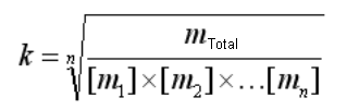
When calculating the diameter of the semi-finished product according to the above method, it is necessary to repeatedly try to take the values of m1, m2, m3, …, mn, which is cumbersome. In fact, the limit drawing coefficient can be enlarged by an appropriate multiple k.
In the formula, n is the number of deep drawing.
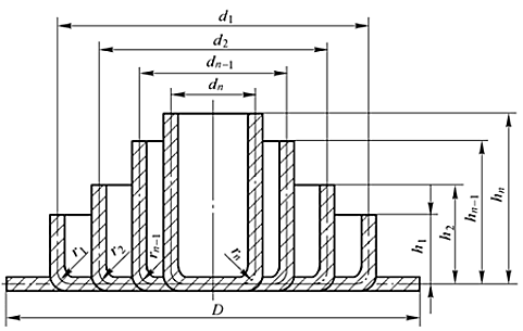
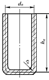
2) Round bottom corner radius rn
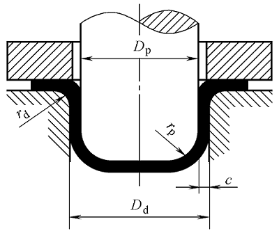
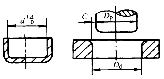
The fillet radius rn at the bottom of the cylinder is the fillet radius rp of the deep drawing die of this process.
The determination method is as follows:
In general, except for the deep drawing process, rpi = rdi is preferable.
For the last drawing process:
When the fillet radius of the workpiece r≥t , then rpn = r;
When the fillet radius of the workpiece is r <t, then rpn> t is taken. After the drawing is finished, r is obtained through the shaping process.
3) Calculation of process part height Hi
According to the principle that the surface area of the process parts after drawing is equal to the surface area of the billet, the following formula for calculating the height of the process parts can be obtained.
Before the calculation, the bottom corner radius of each work piece should be determined.
Hi is solved by the calculation formula of the blank diameter:
Deep drawing process calculation example
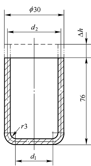
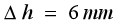
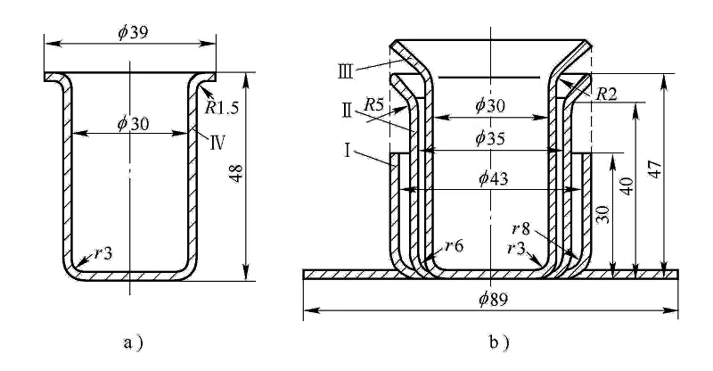
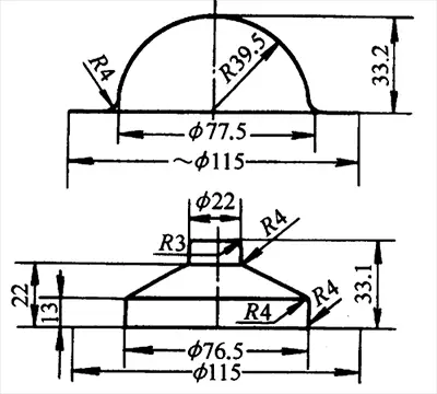
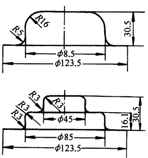
Example 4.1 Find the blank size of the cylindrical part shown in the figure and the dimensions of each drawing process. The material is 10 steel, and the sheet thickness is t = 2mm.
Solution:
Because t> 1mm, it is calculated according to the thickness and diameter of the plate.
(1) Calculate the diameter of the billet
According to the size of the part, its relative height is
Check the table 5-2 to get the cutting margin
Billet diameter is
Substitute the known conditions into the above formula to obtain D = 98.2mm, here D = 98mm
(2) Determine the number of deep drawing
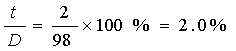
The relative thickness of the blank is:
According to Table 5-1, the blank holder ring can be used or not, but for insurance, the blank holder ring is still used for the first drawing.
Table: Using a binder ring (flat die cavity)
Stretching Method
First stretch
Subsequent stretches
(t/D)×100
m1
(t/D)×100
mn
Using a Flanging Ring
<1.5
<0.60
<1
<0.80
Optional use of a flanging ring
1.5~2.0
0.6
1~1.5
0.8
Without a flanging ring
>2.0
>0.60
>1.5
>0.80
According to t/D=2.0%, check the table 5-3 to get the ultimate drawing coefficient for each drawing process:[m1 ]=0.50,[m2 ]=0.75,[m3 ]=0.78,[m4 ]=0.80,…
Table: Limit drawing coefficient of blank holder for cylindrical parts (08, 10, 15Mn and H62)
Corner radius
Relative thickness of sheet t/D*100
2~15
1.5~1
1~0.6
0.6~0.3
0.3~0.15
0.15~0.08
m1
0.48~0.50
0.5~0.53
0.53~0.55
0.55~0.58
0.58~0.60
0.60~0.63
m2
0.73~0.75
0.75~0.76
0.76~0.78
0.78~0.79
0.79~0.80
0.80~0.82
m3
0.76~0.78
0.78~0.79
0.79~0.80
0.80~0.81
0.81~0.82
0.82~0.84
m4
0.78~0.80
0.80~0.81
0.81~0.82
0.82~0.83
0.83~0.85
0.85~0.86
m5
0.80~0.82
0.82~0.84
0.84~0.85
0.85~0.86
0.86~0.87
0.87~0.88
Therefore,
d1=[m1 ]D=0.50×98mm=49.0mm
d2= [m2 ]d1=0.75×49.0mm=36.8mm
d3= [m3 ]d2=0.78×36.8mm=28.7mm
d4= [m4 ]d3=0.8×28.7mm=23mm
At this time,
d4=23mm<28mm, so it should be drawn 4 times.
Table: The coefficient K1 value for the first draw of cylindrical parts (steel grades 08 to 15)
Relative thickness(t/D0)×100
First-time deep drawing coefficient (m1)
0.45
0.48
0.50
0.52
0.55
0.60
0.65
0.70
0.75
0.80
5.0
0.95
0.85
0.75
0.65
0.60
0.50
0.43
0.35
0.28
0.20
2.0
1.10
1.00
0.90
0.80
0.75
0.60
0.50
0.42
0.35
0.25
1.2
1.10
1.00
0.90
0.80
0.68
0.56
0.47
0.37
0.30
0.8
1.10
1.00
0.90
0.75
0.60
0.50
0.40
0.33
0.5
1.10
1.00
0.82
0.67
0.55
0.45
0.36
0.2
1.10
0.90
0.75
0.60
0.50
0.40
0.1
1.10
0.90
0.75
0.60
0.50
Table: The coefficient K1 value for the first draw of cylindrical parts (steel grades 08 to 15)
Relative thickness(t/D0)×100
Second-time deep drawing coefficient (m2)
0.7
0.72
0.75
0.78
0.80
0.82
0.85
0.88
0.90
0.92
5.0
0.85
0.70
0.60
0.50
0.42
0.32
0.28
0.20
0.15
0.12
2.0
1.10
0.90
0.75
0.60
0.52
0.42
0.32
0.25
0.20
0.14
1.2
1.10
0.90
0.75
0.62
0.52
0.42
0.30
0.25
0.16
0.8
1.00
0.82
0.70
0.57
0.46
0.35
0.27
0.18
0.5
1.10
0.90
0.76
0.63
0.50
0.40
0.30
0.20
0.2
1.00
0.85
0.70
0.56
0.44
0.33
0.23
0.1
1.10
1.00
0.82
0.68
0.55
0.40
0.30
(3) Determination of the size of each drawing process
The diameter of each process part is
d1=k[m1 ]D=1.051185×0.50×98mm=51.51mm
d2=k[m2 ]d1=1.051185×0.75×51.51mm=40.61mm
d3=k[m3 ]d2=1.051185×0.78×40.61mm=33.30mm
d4=k[m4 ]d3=1.051185×0.80×33.30mm≈28mm
The radius of the fillet at the bottom of each process part takes the following values:
r1=8mm,r2=5mm,r3=4mm,r4=4mm
The height of each process part is ……
(4) Process part sketch
Drawing process calculation of flanged cylindrical parts
The flanged cylindrical part can be regarded as a semi-finished product when the flangeless cylindrical part is drawn to a certain point in the middle and stopped.
Same drawing as flangeless tube:
Deformation characteristics are the same.
The quality problems that occur during the drawing process are similar.
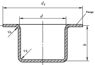
(1) Classification and deformation characteristics of flanged cylindrical parts
1) Narrow flange cylindrical parts
Narrow flange cylinder:
Drawing method and process calculation method are the same as those of flangeless cylindrical parts
2) Wide flange cylindrical parts
df/d>1.4
Drawing method and process calculation are different from flangeless cylindrical parts
(2) Deep drawing method of wide flange cylindrical part
df/d>1.4
Special reminder:
Regardless of the drawing method, the flange size must be obtained during the first drawing. The height of the punch entering the cavity must be strictly controlled.
(3) Process calculation of wide flange cylindrical parts
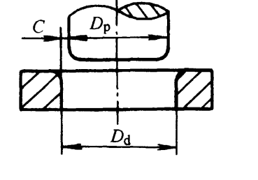
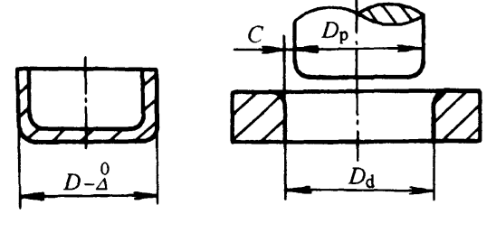
1) Determination of the blank size of the wide flange
Blank unfolding: calculated according to the blank calculation method for flangeless cylindrical parts, that is, the blank surface area is calculated according to the principle of equal surface area.
When rp=rd=r,
df contains trim margin △df
2) Deformation of wide flanged cylindrical parts
The degree of deformation of wide flanged cylindrical parts cannot be measured only by the drawing coefficient
The number of drawing times is determined according to the drawing coefficient and the relative height of the parts.
It is impossible to judge the partof deep drawing and the degree of deformation based on the deep drawing coefficient.
The first ultimate drawing factor is smaller than that of a flangeless tube. Wide flanges have their own drawing coefficients, see table 5-7
The drawing coefficient of a wide flanged cylindrical part depends on three relative ratios of dimensions: df/d (relative diameter of the flange), h/d (relative height of the part), r/d (relative fillet radius ).
Table 5-7 First limit drawing coefficient of wide flange
(3) Judge whether it can be pulled at once
Judging from the drawing coefficient and relative height, find the total drawing coefficient m and the total relative height h/d, find out the limit drawing coefficient [m1] and relative height [h1/d1] that are allowed for the first time, and compare: mtotal> [m1], h/d≤[h1/d1], it can be pulled out at one time, otherwise multiple deep drawing is required.
(4) Determining the number of deep drawing: it can still be calculated by using the extrapolation algorithm.
(5) Determination of the size of the semi-finished product
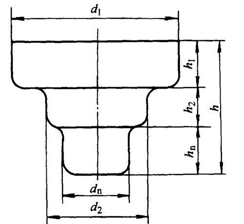
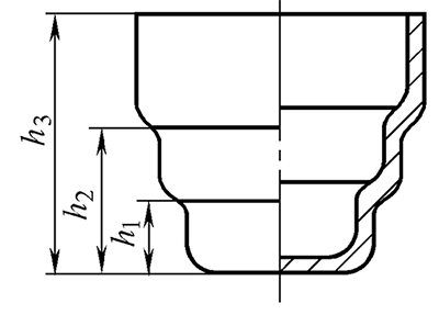
3.Deep drawing of stepped cylindrical parts
Deformation characteristics:
The deep drawing of the stepped part is basically the same as that of the cylindrical part, and each step is equivalent to the drawing of the corresponding cylindrical part.
(1) Judge whether it can be deep-drawn at one time
Judging by the ratio of the part height h to the minimum diameter dn.
If h/dn≤[h1/d1], it can be pulled out once, otherwise it can be drawn multiple times. [h1/d1] can be found in Table 5-5
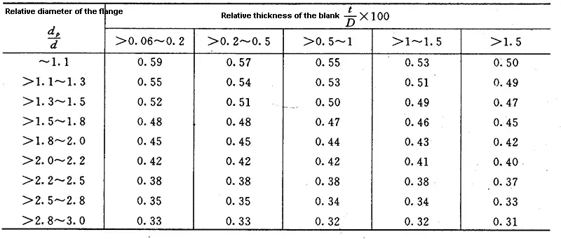
Table: Maximum relative height h1/d1 of wide flange cylindrical parts for first stretching (08, 10 steel)
Unit:mm
Relative diameter dconvex/d
Relative thickness of sheet t/D×100
<2~1.5
<1.5~1.0
<1.0~0.5
<0.5~0.2
<0.2~0.06
≤1.1e
0.75~0.90
0.65~0.82
0.50~0.70
0.50~0.62
0.45~0.52
>1.1~1.3
0.65~0.80
0.56~0.72
0.45~0.60
0.45~0.52
0.40~0.47
>1.3~1.5
0.58~0.70
0.50~0.63
0.42~0.54
0.40~0.48
0.35~0.42
>1.5~1.8
0.48~0.58
0.42~0.53
0.37~0.44
0.34~0.39
0.29~0.35
>1.8~2.0
0.42~0.51
0.36~0.46
0.32~0.38
0.29~0.34
0.25~0.30
>2.0~2.2
0.35~0.45
0.31~0.40
0.27~0.33
0.25~0.29
0.22~0.26
>2.2~2.5
0.28~0.35
0.25~0.32
0.22~0.27
0.20~0.25
0.17~0.21
>2.5~2.8
0.22~0.27
0.19~0.24
0.17~0.21
0.15~0.18
0.13~0.16
>2.8~3.0
0.18~0.22
0.16~0.20
0.14~0.17
0.12~0.15
0.10~0.13
Table: The maximum relative height (h/d) for flangeless cylindrical deep-drawn parts.
Deep drawing time (n)
Relative thickness of the blank t/D×100
2~1.5
<1.5~1
<1~0.6
<0.6~0.3
<0.3~0.15
<0.15~0.08
1
0.94~0.77
0.84~0.65
0.70~0.57
0.62~0.5
0.52~0.45
0.46~0.38
2
1.88~1.54
1.60~1.32
1.36~1.1
1.13~0.94
0.96~0.83
0.9~0.7
3
3.5~2.7
2.8~2.2
2.3~1.8
1.9~1.5
1.6~1.3
1.3~1.1
4
5.6~4.3
4.3~3.5
3.6~2.9
2.9~2.4
2.4~2.0
2.0~1.5
5
8.9~6.6
6.6~5.1
5.2~4.1
4.1~3.3
3.3~2.7
2.7~2.0
Note:
1. The larger h/d ratio is applicable for the initial forming process with larger die fillet radii, ranging from rdi = 8t when t/D0 × 100 = 2-1.5, to rd = 15t when t/D0 × 100 = 0.15-0.08. The smaller ratio applies to smaller die fillet radii [rd = (4–8)t].
The number of drawing stages listed in the table is suitable for deep-drawn parts made of 08 and 10 grade steel.
(2) Determination of deep drawing method for stepped pieces
1) When the ratio of the diameter of any two adjacent steps (dn/dn-1) is greater than the limit drawing coefficient of the corresponding cylindrical part, each step forms a step, from the large step to the small step the number of deep times is the number of steps.
2) If the ratio of the diameters of two adjacent steps (dn/dn-1) is less than the limit drawing coefficient of the corresponding cylindrical part, the drawing method is based on the wide flange part, which is drawn from the small step to the large step.
Drawing method of shallow stepped piece
3.2 Drawing Process Calculation of Non-Straight Wall Rotating Body Parts
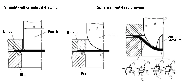
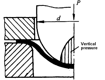
Drawing characteristics of non-straight wall rotating body parts
Deep drawing characteristics of non-straight wall rotating body parts:
(1) When the non-straight wall rotating body part is deepened, the flange portion below the blank holder ring and the suspended portion in the die opening are deformation regions.
(2) The drawing process of non-straight wall rotating body parts is a combination of drawing deformation and bulging deformation.
(3) Bulging deformation is mainly located in the vicinity of the bottom of the punch die
Wrinkling has become a major problem to be solved in the drawing of such parts. Especially the wrinkling of the suspended part-the inner wrinkle
Measures to neither wrinkle nor break
Increase flange size
Increase the friction coefficient under the blank holder
Increase blank holder force
Use drawbead
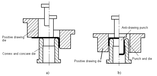
Back draw
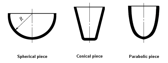
Deep drawing of spherical parts
The drawing coefficient is constant and cannot be used as a basis for process design.
m=0.707
Drawing method for spherical parts
When t / D> 3%, a simple bottomed die without a blank holder can be used for one-time drawing
When t / D = 0.5% ~ 3%, deep drawing die with blank holder is used for deep drawing
When t / D <0.5%, a concave die with deep drawing ribs or reverse deep drawing die is used
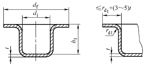
Deep drawing of parabolic parts
Deep drawing is more difficult than spherical parts
Common drawing methods are:
(1) Shallow paraboloid (h/d <0.5 ~ 0.6). Because its height-to-diameter ratio is nearly spherical, the drawing method is the same as that of spherical parts.
(2) Deep paraboloid (h/d> 0.5 ~ 0.6). Its deepening difficulty has increased. At this time, in order to make the middle part of the blank close to the mold without wrinkling, a mold with deep drawing ribs is usually used to increase the radial tensile stress.
Deep drawing of deep paraboloids
Deep drawing of conical parts
Deepening method depends on:h/d2,α
Deep drawing method of cone
(1) For shallow conical pieces (h / d2 <0.25 ~ 0.30, α = 50 ° ~ 80 °), it can be drawn at one time
(2) For medium conical pieces (h / d2 = 0.30 ~ 0.70, α = 15 ° ~ 45 °), the drawing method depends on the relative material thickness:
1) When t / D> 0.025, the blanking ring can be used for one-time drawing.
2) When t / D = 0.015 ~ 0.20, it can be drawn at one time, but measures such as blank holder ring, deep drawing ribs and adding process flanges are required.
3) When t / D <0.015, it is easy to wrinkle because the material is thin. It is necessary to use a blank holder mold and draw it twice.
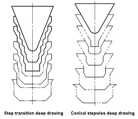
(3) For highly tapered parts (h / d2> 0.70 ~ 0.80, α≤10 ° ~ 30 °), adopt:
1) Step transition deep drawing method
2) Stepwise deep drawing of cone surface
Deep forming method of high-cone piece
3.3 Calculation of deep drawing process of flangeless box
The box-shaped part is a non-rotating body part. When deep drawing is deformed, the rounded part is equivalent to the deep drawing of cylindrical part, and the straight edge part is equivalent to bending deformation.
Before deformation:
Δl1=Δl2=Δl3
Δh1=Δh2=Δh3
After deformation:
Δh1<Δh1′<Δh2′<Δh3′
Δl1>Δl1′>Δl2′>Δl3′
Drawing features of box-shaped parts:
(1) The material in the flange deformation zone is subject to the combined effect of radial tensile stress and tangential compressive stress, resulting in radial deformation and tangential compression deep deformation. The distribution of stress and strain is uneven, with the rounded corners being the largest and the straight edges being the smallest.
(2) The amount of deformation of the straight edge and the fillet in the deformation area is different.
(3) The degree of mutual influence between the straight edge portion and the rounded corner portion varies with the shape of the box.
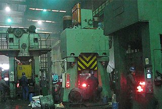
3.4 Deep drawing process force calculation and equipment selection
Blank holding force and blank holding device
(1) Blank holding force
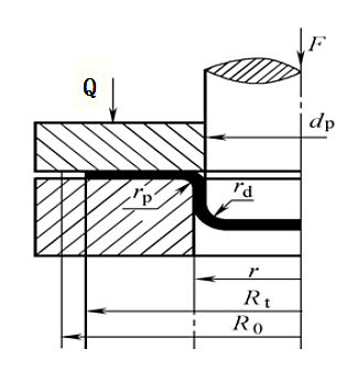
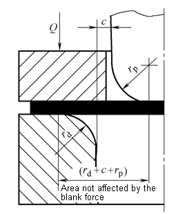
The blank holding force Q is provided by a blank holding device provided in a mold.
The blank holding force Q generated by the blank holder should be as small as possible on the premise of ensuring that the deformation area does not wrinkle.
The required blank holder force for deep drawing parts of any shape: Q = Aq
In the formula:
A- the projected area of the blank under the blank holder
q- Pressing force per unit area, q = σb / 150
Blank holder force for straight wall cylindrical parts
Deep drawing of straight wall cylindrical parts for the first time:
Deep drawing of straight wall cylindrical parts in the subsequent process:
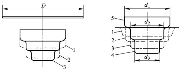
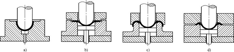
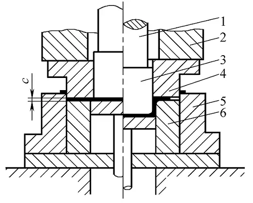
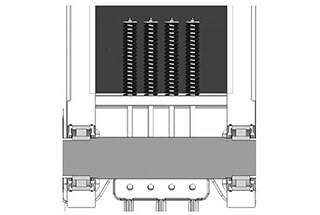
(2) Blank holder
The function of the blank holder is to prevent wrinkling in the deep deformation zone.
Depending on the source of the blank holder force, there are two types of blank holder devices:
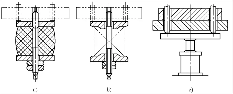
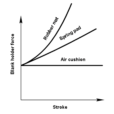
Elastic blank holder: used for single-acting punch, blank holder force is provided by spring, rubber, air cushion, nitrogen spring, etc.
Rigid blank holder: used for double action punch, blank holder force is provided by outer slider.
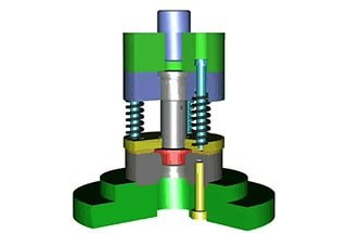
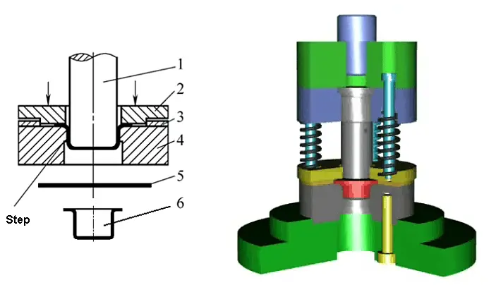
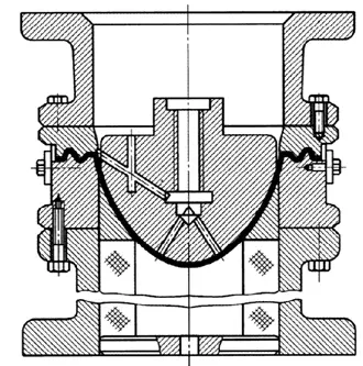
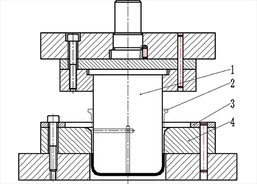
Elastic blank holder
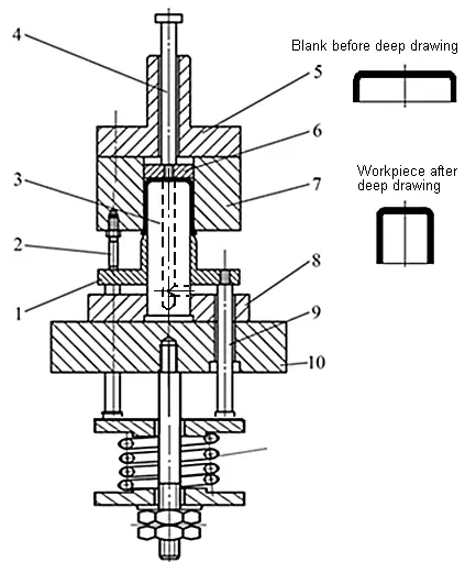
Application example of elastic blank holder
7–blank ring
Rigid blank holder on double action press
4–blank ring
Calculation of drawing force
For cylindrical, elliptical, box-shaped parts, the drawing force is:
Fi– drawing force of the i-th drawing, the unit is N;
Ls– perimeter of workpiece section (according to material thickness center), unit is mm;
Kp– For deep drawing of cylindrical parts, Kp = 0.5 ~ 1.0; For deep drawing of oval parts and box-shaped parts, Kp = 0.5 ~ 0.8; For deep drawing of other shapes, Kp = 0.7 ~ 0.9. When the drawing approaches the limit, Kp takes a large value; otherwise, it takes a small value.
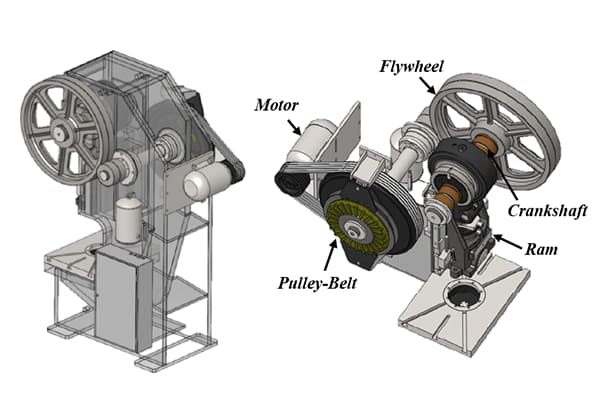
Deep drawing equipment selection
For single-acting presses, the nominal pressure of the equipment should meet:
FE > Fi + Q
For double-acting presses, the tonnage of the equipment should meet:
Finner > Fi
Fouter > Q
Pay attention:
When the drawing working stroke is large, especially when the blanking drawing is combined, the process force curve should be below the allowable pressure curve of the press slider.
In actual production, the nominal pressure Fpressure of the press can be determined by the following formula:
Shallow drawing: ΣF ≤ (0.7~0.8)Fpress
Deep drawing: ΣF ≤ (0.5~0.6)Fpress
Deep drawing process design
4.1 Deep drawing process analysis
The processability of the drawn part refers to the adaptability of the drawn part to the drawing process.
The analysis of whether a deep-drawn part is suitable for deep drawing is mainly based on the structural shape, size, dimensioning, accuracy and material selection of the deep-drawn part, which is a requirement for product design from the perspective of product processing.
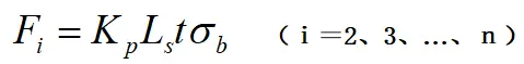
Deep drawing shape
(1) The shape of the drawn part should be as simple and symmetrical as possible, and it should be drawn as soon as possible. Try to avoid sharp shape changes.
2) Shape error of the drawn part
Drawing height
The height dimension of the drawn parts should be reduced as much as possible, and drawn as far as possible.
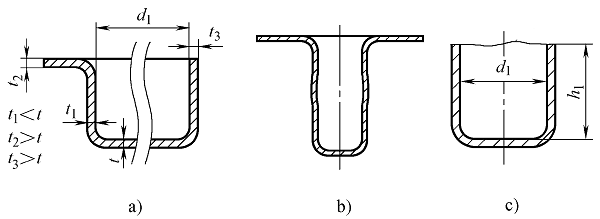
Deep drawing flange width
Flange of flanged straight wall cylinder
The diameter should be controlled at:
d1 + 12t ≤ df ≤ d1+25t
Wide flange straight wall cylinder:
df ≤ 3d1, h1 ≤ 2d1
The flange width of the drawn part should be as consistent as possible and similar to the contour shape of the drawn part.
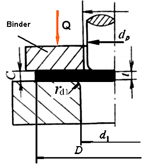
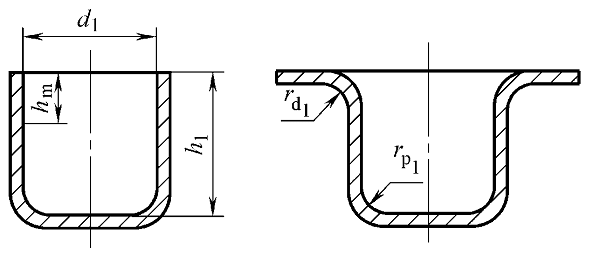
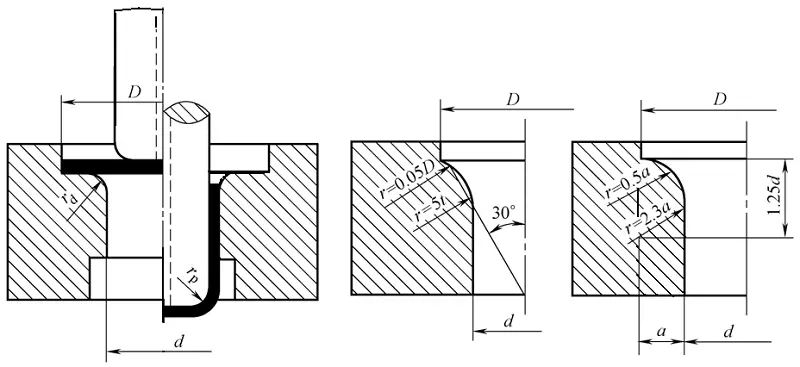
Fillet radius of drawn parts
Rounded corners of bottoms and walls, flanges and walls of drawn parts
The radius should satisfy:
rp1 ≥ t, rd1 ≥ 2t, rc1 ≥ 3t
Otherwise, plastic surgery procedures should be added.
Punching design for deep drawing
Distance between punched holes on the flange of the drawn part: ≥5t
Distance between punched holes on the side wall of the drawn part: hd≥ 2dh + t
The hole position on the drawing part should be set on the same plane as the main structural surface (flange surface), or the hole wall should be perpendicular to this plane
The hole in the drawing part is usually punched after the drawing is finished.
Small plastic strain ratio anisotropy coefficient Δγ
4.2 Deep drawing process arrangement
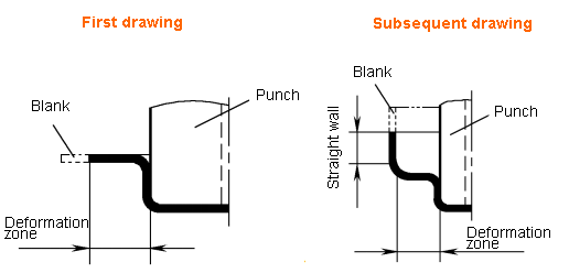
1) If it is a shallow drawn part that can be formed in one drawing, the blanking drawing composite process is used to complete it.
2) For high-drawing parts, single-step stamping can be used when the batch size is not large; when the batch size is large and the size of the deep-drawn parts is not large, progressive drawing with strip can be used.
3) If the size of the drawn part is large, usually only single-step stamping can be used.
4) When the drawing parts have higher accuracy requirements or need to draw a small fillet radius, it is necessary to add a shaping process after the drawing is finished.
5) The trimming and punching processes of deep-drawn parts can usually be completed in combination.
6) Except that the bottom hole of the drawing part may be compounded with blanking and drawing, the holes and grooves of the flange part and side wall part of the drawing part must be punched out after the drawing process is completed.
7) If other forming processes (such as bending, flipping, etc.) are required to complete the shape of the drawn part, other stamping processes must be performed after the drawing is finished.
As the founder of MachineMFG, I have dedicated over a decade of my career to the metalworking industry. My extensive experience has allowed me to become an expert in the fields of sheet metal fabrication, machining, mechanical engineering, and machine tools for metals. I am constantly thinking, reading, and writing about these subjects, constantly striving to stay at the forefront of my field. Let my knowledge and expertise be an asset to your business.
Wrinkling in metal stamping can undermine the quality of stamped parts, but it can be controlled through specific practices. This article explores factors like stretch depth, blank holder force, and…
Intrigued by the marvels of metal stamping? In this blog post, we dive into the fascinating world of hole flanging, necking, and bulging. Our expert mechanical engineer will guide you…
Have you ever wondered about the process behind the precise shapes cut out of metal sheets? In this fascinating article, we delve into the world of blanking, a crucial technique…
Have you ever wondered about the fascinating world of metal stamping? In this blog post, we'll embark on an exciting journey to explore the intricacies of this essential manufacturing process.…
Have you ever wondered how the machines that shape our world are made? This blog takes you on a journey through the top punch press machine manufacturers. You'll learn about…
Have you ever wondered how forging equipment is selected for different applications? In this blog post, we'll explore the key factors that influence the choice of forging hammers, screw presses,…
Imagine your forging machinery vibrating so intensely it disrupts operations and damages equipment. Why does this happen, and how can you stop it? This article dives into the causes of…
Have you ever wondered how a punch press transforms metal sheets into precise shapes? In this article, you'll discover the inner workings of punch presses, from their rotary-to-linear motion mechanism…
Imagine cutting manufacturing costs while boosting efficiency. The secret lies in the intricate design of continuous dies. This article reveals key considerations for precision and durability, ensuring your stamping process…