Discover the secret language that brings machines to life! In this captivating blog post, we’ll dive into the fascinating world of G-code and M-code, the essential programming commands that power CNC machining. Whether you’re a seasoned engineer or a curious learner, join us as we unravel the mysteries behind these codes and explore how they enable machines to perform complex tasks with unparalleled precision. Get ready to be amazed by the incredible potential of CNC programming!
In CNC machining, G-codes and M-codes are two fundamental programming commands used to control the movement and functionality of machine tools.
G-code, also known as “geometric code” or “preparatory code,” is primarily used to define the motion and positioning of the cutting tool. These codes instruct the machine on how to move, such as rapid motion (G00), linear interpolation (G01), and circular interpolation (G02 and G03), among others.
On the other hand, M-code, also known as “miscellaneous code,” controls various functions of the machine tool, such as spindle rotation, coolant flow adjustment, and tool change. Each G and M code is usually followed by a number representing a specific function or command.
The existence of G-codes and M-codes enables CNC machine tools to perform complex machining tasks. By precise programming instructions, they control the actions of the machine tool, resulting in high precision and high-quality machining effects.
Different combinations of G and M codes can complete various machining operations, including but not limited to drilling, milling, and turning. However, it’s important to note that different manufacturers’ CNC systems may have variations in the specific meanings and applications of these codes. Therefore, reference to the specific machine tool’s operating manual or consultation with the manufacturer is necessary to ensure correct application.
In summary, G-codes and M-codes are indispensable parts of CNC machining. Together, they form the programming language of CNC machine tools, making the mechanical machining process more flexible and efficient. Mastery of these codes’ meanings and applications is crucial for CNC programmers.
What is G-code?
G-code (also known as RS-274) is the most widely used numerical control (NC) programming language in computer-aided manufacturing (CAM). It serves as a standardized set of instructions for controlling automated machine tools, including CNC mills, lathes, 3D printers, and other computer-controlled manufacturing equipment.
Developed in the 1950s by the Electronic Industries Alliance (EIA), G-code has evolved through various versions and implementations. Despite its name, G-code encompasses not only “G” commands (preparatory functions) but also “M” codes (miscellaneous functions), coordinate values, and other parameters that collectively form a comprehensive machine control language.
Key features and applications of G-code include:
Motion control: Rapid positioning, linear and circular interpolation, and complex path generation.
Coordinate systems: Defining work coordinates and performing coordinate transformations.
Program flow: Implementing loops, subroutines, and conditional statements.
Machine-specific functions: Controlling unique features of different machine tools.
G-code instructions typically follow a structured format, with each line representing a single command or set of parameters. For example:
G01 X100 Y50 F500
This instruction directs the machine to move linearly (G01) to the X-coordinate of 100mm and Y-coordinate of 50mm at a feed rate of 500mm/minute.
While G-code remains the industry standard, modern CAM software often generates G-code automatically from 3D models and toolpath strategies, simplifying the programming process for complex parts. However, understanding G-code fundamentals remains crucial for optimizing machining processes, troubleshooting, and fine-tuning automated manufacturing operations.
What is M-code?
M-code, short for Miscellaneous code, is a crucial component of CNC (Computer Numerical Control) programming, specifically defined as an auxiliary function code in FANUC and other control systems. These codes play a vital role in controlling various non-axis movement functions of the machine tool, complementing G-codes which primarily handle motion and cutting operations.
M-codes are used to command auxiliary operations that are essential for the overall machining process but do not directly involve the movement of cutting tools or workpiece positioning. These functions can include:
Coolant control (e.g., M08 for coolant on, M09 for coolant off)
Spindle operations (e.g., M03 for spindle clockwise, M04 for counterclockwise, M05 for spindle stop)
Tool changes (e.g., M06 for automatic tool change)
Program flow control (e.g., M00 for program stop, M01 for optional stop)
Pallet changes (e.g., M60 in some systems)
Special machine functions (e.g., M21, M22 for custom operations specific to a particular machine)
The implementation and specific functions of M-codes can vary slightly between different machine manufacturers and control systems, although many standard codes are widely recognized across platforms. Proper use of M-codes is essential for efficient and safe operation of CNC machines, allowing for precise control over various machine functions throughout the manufacturing process.
The program is suspended. Press the ‘cycle start’ program to continue
M30
The program ends and returns to the beginning
19. GSK928 TC / TE G code
G-code
Function
G00
Positioning (fast moving)
*G01
Linear interpolation (cutting feed)
G02
Arc interpolation CW (clockwise)
G03
Circular interpolation CCW (counterclockwise)
G32
Tapping circulation
G33
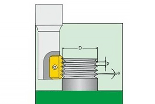
Thread cutting
G71
Outer circle rough turning cycle
G72
End rough turning cycle
G74
End face deep hole machining cycle
G75
Outer circle, inner circle, grooving cycle
G90
Outer circle, inner circle, turning cycle
G92
Thread cutting cycle
G94
Outer circle inner conical surface circulation
G22
Local cycle start
G80
End of local cycle
*G98
Feed per minute
G99
Feed per revolution
G50
Set workpiece absolute coordinate system
G26
10. Z-axis back reference
G27
X-axis back to reference point
G29
Z axis back to reference point
20. GSK928 TC / TEM code
M-code
Instruction
M03
Spindle forward rotation
M04
Spindle reversal
M05
Spindle stop
M08
Coolant on
M09
Coolant off (no output signal)
M32
Lubrication on
M33
Lubrication off (no output signal)
M10
Spare
M11
Spare tip (no signal output)
MOO
Program pause, press’ cycle start ‘program to continue
M30
The program ends and returns to the beginning
21. GSK990M G Code
G-code
Group
Explain
G00
1
Positioning (fast moving)
G01
Linear cutting
G02
Clockwise circular arc
G03
Counterclockwise tangent arc
G04
0
suspend
G17
2
XY face assignment
G18
XZ face assignment
G19
YZ face assignment
G28
0
Machine return to origin
G29
Return from reference point
*G40
7
Cancel tool diameter offset
G41
Tool diameter left offset
G42
Tool diameter right offset
*G43
8
Tool length + direction offset
*G44
Tool length minus direction offset
G49
Cancel tool length offset
*G53
14
machine tool coordinate system selection
G54
workpiece coordinate system 1 Selection
G55
workpiece coordinate system 2 selection
G56
workpiece coordinate system 3 selection
G57
workpiece coordinate system 4 selection
G58
workpiece coordinate system 5 Selection
G59
workpiece coordinate system 6 selection
G73
9
high speed deep hole drilling cycle
G74
left spiral cutting cycle
G76
fine boring cycle
*G80
cancel fixed cycle
G81
drilling cycle (spot drilling)
G82
drilling cycle (boring stepped holes)
G83
deep hole drilling cycle
G84
tapping cycle
G85
boring cycle
G86
borehole circulation
G87
reverse boring cycle
G88
boring cycle
G89
boring cycle
*G90
3
use absolute value command
G91
use incremental value command
G92
0
set workpiece coordinate system
*G98
10
fixed cycle return to starting point
*G99
return to fixed cycle r point
22. GSK990M M code
M-code
Instruction
M00
Program stop
M01
Select Stop
M02
Program end (reset)
M03
Spindle forward rotation (CW)
M04
Spindle reversal (CCW)
M05
Spindle stop
M06
Change knife
M08
Cutting fluid on
M09
Cutting fluid off
M10
Clamping
M11
Release
M32
Lubrication on
M33
Lubrication off
M98
Subroutine call
M99
End of subroutine
23. GSK928MA G-code
G-code
Explain
G00
Positioning (fast moving)
G1
Linear cutting
G02
Clockwise circular arc
G03
Counterclockwise tangent arc
G04
Delay waiting
G17
XY face assignment
G18
XZ face assignment
G19
YZ face assignment
G28
Machine return to origin
G29
Return from reference point
*G40
Cancel tool diameter offset
G41
Tool diameter left offset
G42
Tool diameter right offset
*G43
Tool length + direction offset
*G44
Tool length offset in one direction
G49
Cancel tool length offset
*G53
Machine coordinate system selection
G54
Workpiece coordinate system 1 Selection
G55
Workpiece coordinate system 2 selection
G56
Workpiece coordinate system 3 selection
G57
Workpiece coordinate system 4 selection
G58
Workpiece coordinate system 5 Selection
G59
Workpiece coordinate system 6 selection
G73
High speed deep hole drilling cycle
G74
Left spiral cutting cycle
G80
Cancel fixed cycle
G81
Drilling cycle (spot drilling)
G82
Drilling cycle (boring stepped holes)
G83
Deep hole drilling cycle
G84
Right tapping circulation
G85
Boring cycle
G86
Drilling cycle
G89
Boring cycle
*G90
Use absolute value command
G91
Use incremental value command
G92
Set floating coordinate system
*G98
Fixed cycle return to starting point
*G99
Return to fixed cycle r point
G10 G11
Rough milling in circular groove
G12 G13
Full circle internal finish milling
G14 G15
Cylindrical finish milling
G22
System parameter operation (mode)
G23
Parameter value jump
G27
Mechanical zero point detection
G28
Quickly locate the program through the middle point
G31
Quick return to R datum
G34 G35
Finish milling in rectangular groove
G38 G39
Rectangular external finish milling
24. GSK928MAMcode
M2
The program ends and stops. Stop the spindle, turn off the coolant, eliminate the G93 coordinate offset and tool offset, and return to the starting program section (not running). After executing M2, the system will switch to the reference workpiece coordinate system.
M3
Spindle forward rotation
M4
Spindle reversal
M5
Stop spindle
M8
Turn on the cooling pump
M9
Turn off the cooling pump
M12
Pause: wait for the “run” key to continue running (press the emergency stop key to stop)
M30
At the end of the program, eliminate the tool offset and return to the starting program segment (not running). After executing M30, the system will switch to the reference workpiece coordinate system.
M32
Lubrication on;
M33
Lubrication off;
M98
Call subroutine
M99
Subroutine end return
25. Mitsubishi E60 milling machine G code
G-code
Group
Explain
※G00
1
Position positioning (rapid feed)
*G01
Straight line repair
G02
Clockwise arc cutting (CW)
G03
Counterclockwise arc cutting (CCW)
G04
0
suspend
G05
High speed machining mode
G09
Stop the check correctly
G10
Program parameter input / correction input
G11
Program parameter input cancel
G12
Circular cutting CW
G13
Circular cutting CCW
*G17
2
Plane selection X-Y
※G18
Plane selection z-x
G19
Plane selection Y-Z
※G20
6
Imperial directive
G21
Metric instruction
G27
0
Reference origin check
G28
Reference origin reset
G29
Start point reset
G30
The 2nd ~ 4th reference origin reset
G31
Jumping function
G33
1
Thread cutting
G37
0
Automatic tool length measurement
G38
Tool diameter correction vector assignment
G39
Angle arc correction tool
*G40
7
Tool diameter correction cancellation
G41
Tool diameter correction left
G42
Tool diameter correction right
G43
8
Tool length correction (+)
G44
Tool length correction (I)
*G49
Tool length correction quantity cancellation
G52
0
Local coordinate system setting
G53
Selection of mechanical coordinate system
*G54
12
Workpiece coordinate system 1 Selection
G55
12
Workpiece coordinate system 2 selection
G56
Workpiece coordinate system 3 selection
G57
Workpiece coordinate system 4 selection
G58
Workpiece coordinate system 5 Selection
G59
Workpiece coordinate system 6 selection
G60
0
Unidirectional position positioning
G61
13
Make sure to stop the inspection mode
G62
Automatic angle feed rate adjustment
G63
Tapping mode
*G64
Cutting mode
G73
9
Fixed cycle (step cycle)
G74
Fixed circulation (reverse tapping)
G76
Fixed cycle (fine boring)
*G80
Fixed cycle cancellation
G81
Fixed circulation (drilling / lead hole)
G82
Fixed cycle (drilling / counter boring)
G83
Fixed circulation (deep drilling)
G84
Fixed circulation (tapping)
G85
Fixed cycle (boring)
G86
Fixed cycle (boring)
G87
Fixed cycle (reverse boring)
G88
Fixed cycle (boring)
G89
Fixed cycle (boring)
*G90
3
Absolute value instruction
*G91
Incremental value instruction
G92
0
Mechanical coordinate system setting
G93
5
Counterclockwise feed
*G94
Asynchronous cutting (feed per minute)
*G95
Simultaneous cutting (feed for each drilling)
*G96
17
The cycle speed must be controlled effectively
*G97
The cycle speed control must be invalid
*G98
10
Fixed cycle starting point reset
G99
Fixed cycle r-point reset
26. DASEN 3I milling machine G code
G-code
Group
Explain
※G00
1
Position positioning (rapid feed)
*G01
Straight line repair
G02
Clockwise arc cutting (CW)
G03
Counterclockwise arc cutting (CCW)
G04
0
suspend
G05
High speed machining mode
G09
Stop the check correctly
G10
Program parameter input / correction input
G11
Program parameter input cancel
G12
Circular cutting CW
G13
Circular cutting CCW
*G17
2
Plane selection X-Y
※G18
Plane selection z-x
G19
Plane selection Y-Z
※G20
6
Imperial directive
G21
Metric instruction
G27
0
Reference origin check
G28
Reference origin reset
G29
Start point reset
G30
The 2nd ~ 4th reference origin reset
G31
Jumping function
G33
1
Thread cutting
G37
0
Automatic tool length measurement
G38
Tool diameter correction vector assignment
G39
Angle arc correction tool
*G40
7
Tool diameter correction cancellation
G41
Tool diameter correction left
G42
Tool diameter correction right
G43
8
Tool length correction (+)
G44
Tool length correction (I)
*G49
Tool length correction quantity cancellation
G52
0
Local coordinate system setting
G53
Selection of mechanical coordinate system
*G54
12
Workpiece coordinate system 1 Selection
G55
12
Workpiece coordinate system 2 selection
G56
Workpiece coordinate system 3 selection
G57
Workpiece coordinate system 4 selection
G58
Workpiece coordinate system 5 Selection
G59
Workpiece coordinate system 6 selection
G60
0
Unidirectional position positioning
G61
13
Make sure to stop the inspection mode
G62
Automatic angle feed rate adjustment
G63
Tapping mode
*G64
Cutting mode
G73
9
Fixed cycle (step cycle)
G74
Fixed circulation (reverse tapping)
G76
Fixed cycle (fine boring)
*G80
Fixed cycle cancellation
G81
Fixed circulation (drilling / lead hole)
G82
Fixed cycle (drilling / counter boring)
G83
Fixed circulation (deep drilling)
G84
Fixed circulation (tapping)
G85
Fixed cycle (boring)
G86
Fixed cycle (boring)
G87
Fixed cycle (reverse boring)
G88
Fixed cycle (boring)
G89
Fixed cycle (boring)
*G90
3
Absolute value instruction
*G91
Incremental value instruction
G92
0
Mechanical coordinate system setting
G93
5
Counterclockwise feed
*G94
Asynchronous cutting (feed per minute)
*G95
Simultaneous cutting (feed for each drilling)
*G96
17
The cycle speed must be controlled effectively
*G97
The cycle speed control must be invalid
*G98
10
Fixed cycle starting point reset
G99
Fixed cycle r-point reset
27. DASEN 3I lathe G code
G-code
Group
Explain
※G00
1
Fast mobile positioning
※G01
Straight line repair
G02
Arc gap (CW, Clockwise Clock)
G03
Arc gap repair (CCW, counter clock)
G04
0
suspend
G09
Correct stop
G10
Program parameters / correction input
G11
Program parameter / correction input mode cancelled
※G17
2
X-Y plane selection
※G18
Z-x plane selection
※G19
Y-Z plane selection
※G20
6
Imperial input
※G21
Metric input
G27
0
Reference point reset check
G28
Automatic reference point reset
G29
Reset from reference point
G30
Reset of reference points 2, 3 and 4
G31
Jumping function
G33
1
Thread cutting
G34
Variable thread cutting
G37
0
Automatic tool correction
*G40
7
Tool diameter correction cancellation
G41
Tool diameter correction (left side)
G42
Tool diameter correction (right side)
G46
Tool diameter correction (automatic direction selection)
G52
0
Local coordinate system setting
G53
Selection of mechanical coordinate system
※G54
12
Workpiece coordinate system selection 1
G55
Workpiece coordinate system selection 2
G56
Workpiece coordinate system selection 3
G57
Workpiece coordinate system selection 4
G58
Workpiece coordinate system selection 5
G59
Workpiece coordinate system selection 6
G61
13
Correct stop check mode
G62
Automatic angle speed control
G63
Tapping mode
*G64
Cutting mode
G70
9
Finish cutting cycle
G71
Straight turning rough cutting cycle
G72
End face rough cutting cycle
G73
Spindle table movement in rough machining cycle
G74
End cutting cycle
G75
Straight turning cycle
G76
Thread cutting cycle
G77
From cutting cycle
G78
Tooth fixation cycle
G79
End cutting fixed cycle
G80
Machining hole cycle command cancel
G83
Deep drilling cycle (Z-axis)
G84
Tapping cycle (Z axis)
G85
Boring cycle (Z axis)
G87
Deep hole drilling cycle (x-axis)
G88
Tapping cycle (x-axis)
G89
Boring cycle (x-axis)
※G90
3
Absolute value command
※G91
Incremental value command
G92
0
Coordinate system setting / spindle speed setting
※G94
5
Asynchronous feed (feed per minute)
※G95
Synchronous feed (feed per revolution)
※G96
17
Cycle speed control on
※G97
Cycle speed must be controlled off
*G98
10
Fixed cycle
Initial value reversion
G99
Fixed cycle
R-point reset
28. Huaxing lathe G code
G-code
Explain
G00
Fast positioning
G01
Linear interpolation
G02
Clockwise circular interpolation
G03
Counterclockwise circular interpolation
G04
delayed
G09
Feed quasi stop
G20
Independent subroutine call
G22
Independent subroutine definition
G24
When the independent subroutine definition is finished, return to the calling program
G25
Jump processing
G26
Block call subroutine call in machining program
G27
Infinite loop
G30
Magnification cancellation
G31
Magnification definition
G47
Short linear speed automatic transition
G48
cancel
G54~G59
Workpiece coordinate system selection
G71
Internal and external circular cutting
G72
Face cutting compound cycle
G73
Closed contour compound cycle
G74
Return to machine reference point (mechanical origin)
G75
Return to tool setting point
G76
Return to machining start point
G77
Restore the current coordinate system
G81
Cylindrical machining cycle
G82
End face machining cycle
G85
Inch rigid tapping cycle
G86
Metric thread machining cycle
G87
Inch thread machining cycle
G90
Absolute value mode programming
G91
Incremental value programming
G92
Set program zero
G96
Constant linear speed cutting is effective
G97
Cancel constant linear speed cutting
G98
Cancel feed per revolution
G99
Set feed per revolution
P = parameter assignment
29. Huaxing lathe M code
M instruction
Explain
M01
Conditional stop
M02
Program end and shutdown
M03
Spindle forward rotation
M04
Spindle reversal
M05
Spindle stop
M06
Cooling on
M07
Cooling off
M08
Workpiece clamping
M09
Workpiece loosening
M10
Turn on the specified relay
M11
Turn off the specified relay
M20
Set tool complement number
M21
The program ends and returns to the beginning of the program
M71~M85
Relay pulse output
30. Huaxing milling machine G code
G-code
Explain
G01
linear interpolation
G02
Clockwise arc interpolation or spiral interpolation
G03
Counterclockwise arc interpolation or spiral interpolation
G04
delayed
G09
Servo quasi stop in place
G11
The block is mirrored along the Y axis
G12
The block is mirrored along the X axis
G13
The program block is processed by mirror image at the origin
G17
Select the xoy plane
G18
Select the x0z plane
G19
Select the y0z plane
G20
Subroutine call
G22
subprogram declaration
G24
The subroutine definition ends and returns to the calling program
G25
Jump processing
G26
Transfer processing
G27
Infinite loop
G30
Zoom in / out magnification cancel
G31
Definition of magnification / reduction ratio
G40
Cancel tool radius compensation
G41
Left tool radius compensation
G42
Right tool radius compensation
G43
Establish tool length compensation
G44
Undo tool length compensation
G47
Short linear speed automatic transition
G48
Cancel the automatic transition of short linear speed
G54~G59
Workpiece coordinate system selection
G73
High speed deep hole machining cycle
G74
Return to machine reference point (mechanical origin)
G75
Return to tool setting point
G76
Return to program zero from current position
G78
Fine boring cycle
G81
Central hole drilling cycle
G82
Central drilling cycle with pause
G83
Deep hole machining cycle
G84
Metric rigid tapping cycle
G85
Inch rigid tapping cycle
G86
Boring cycle (automatic return)
G87
Reverse boring cycle
G88
Boring cycle (manual return)
G89
Boring cycle with pause
G90
Absolute value mode programming
G91
Incremental value programming
G92
Set workpiece coordinate system
P = parameter assignment
31. Huaxing milling machine M code
G-code
Explain
M00
Program pause
M01
L ×× (K ××)
M02
Program end and shutdown
M03
Spindle forward rotation
M04
Spindle reversal
M05
Spindle stop
M08
Cooling on
M09
Cooling off
M10
Workpiece clamping
M11
Workpiece loosening
M20
K ×× Relay No
M21
K ×× shut ×× Relay No
M30
The program ends and returns to the beginning of the program
How do you select the appropriate G-codes and M-codes for programming based on different CNC systems?
To select the appropriate G-codes and M-codes for programming based on different CNC systems, a comprehensive approach considering system specifics, processing requirements, and industry best practices is essential. Here’s an optimized explanation:
System-Specific Knowledge:
Thoroughly understand the characteristics and capabilities of the specific CNC system you’re working with (e.g., Fanuc, Siemens, Heidenhain). Each system may have unique implementations of G and M codes, custom cycles, or proprietary functions. Consult the manufacturer’s programming manuals and keep updated on the latest firmware versions and supported features.
Code Functionality and Hierarchy:
Master the fundamental functions of G and M codes:
G-codes: Motion control, coordinate system selection, canned cycles, etc.
M-codes: Auxiliary functions like spindle control, coolant management, tool changes. Understand the modal nature of certain codes and their hierarchy within the control system to avoid conflicts and ensure proper execution.
Process-Driven Selection:
Choose codes based on the specific machining operations and part requirements:
For contouring: G01 (linear interpolation), G02/G03 (circular interpolation)
For rapid movements: G00 (rapid positioning)
For complex geometries: Consider using parametric programming or canned cycles
For tool management: Appropriate M-codes for tool changes and coolant control
Optimization for Efficiency:
Select codes that optimize machining efficiency:
Use high-speed machining codes when applicable (e.g., G05.1 for Fanuc)
Implement canned cycles (e.g., G81 for drilling) to reduce program length and simplify programming
Utilize advanced features like tool center point control (TCPC) for 5-axis machining when available
Coordinate Systems and Workpiece Setup:
Properly select and utilize coordinate system codes:
G54-G59 for workpiece coordinate systems
G17/G18/G19 for plane selection in circular interpolation and canned cycles Consider using features like coordinate system rotation (G68) for multi-sided machining when appropriate.
Safety and Compliance:
Incorporate safety-related codes and best practices:
Use M00 (program stop) or M01 (optional stop) for critical inspection points
Implement G43 (tool length compensation) to prevent collisions
Include M30 (program end and rewind) to ensure proper program termination
Machine-Specific Optimizations:
Leverage machine-specific features:
For high-speed machining centers: Use look-ahead functions (e.g., G05.1 Q1 for Fanuc)
For multi-axis machines: Implement RTCP (Rotation Tool Center Point) functions when available
For turn-mill centers: Utilize specialized codes for synchronizing spindles and live tooling
Testing and Validation:
Rigorously test your code selections:
Use simulation software to verify tool paths and identify potential issues
Perform dry runs and single block execution to ensure proper code functionality
Validate the program on the actual machine, starting with reduced feed rates for safety
Documentation and Standardization:
Develop and maintain a standardized code library for common operations within your organization. This promotes consistency, reduces programming errors, and facilitates knowledge transfer among team members.
By following this comprehensive approach, you can select the most appropriate G and M codes for your specific CNC system, ensuring efficient, safe, and optimized machining processes. Remember to continuously update your knowledge as CNC technology and programming techniques evolve.
In practical CNC machining, how can G-codes and M-codes be effectively combined to enhance machining efficiency and precision?
In practical CNC machining, effectively combining G-codes and M-codes is crucial for enhancing machining efficiency and precision. This integration requires a deep understanding of both code types and their strategic application within the machining process.
G-codes, which control tool movement and cutting operations, form the backbone of CNC programming. Key G-codes include G00 (rapid positioning), G01 (linear interpolation), G02/G03 (circular interpolation), and G81-G89 (canned cycles for drilling, boring, and tapping). M-codes, on the other hand, manage auxiliary functions such as coolant control (M08/M09), spindle control (M03/M04/M05), and tool changes (M06).
To optimize machining efficiency and precision:
Streamline tool paths: Utilize advanced G-code functions like G70 (finishing cycle) and G71-G73 (stock removal cycles) for efficient material removal. Implement high-speed machining techniques using G05 (high-speed mode) when appropriate, reducing cycle times while maintaining accuracy.
Optimize cutting parameters: Combine G96 (constant surface speed control) with appropriate M-codes for spindle speed control to maintain optimal cutting conditions throughout the process, especially for parts with varying diameters.
Intelligent coolant management: Use M08/M09 in conjunction with through-tool coolant activation (e.g., M88) at critical points in the program. This ensures proper cooling and chip evacuation, particularly during high-precision operations or when machining difficult materials.
Adaptive tool changes: Implement smart tool change strategies using M06 in combination with tool life monitoring G-codes (G43.4 for tool length compensation). This minimizes unnecessary tool changes while ensuring consistent machining quality.
Coordinate system optimization: Utilize multiple coordinate systems (G54-G59) in conjunction with G92 (coordinate system setting) to minimize setup times for complex parts or multi-operation jobs.
Probing and in-process measurement: Integrate probing cycles (G31) with M-codes for automatic workpiece alignment and in-process dimension checking, enhancing overall precision and reducing scrap rates.
Macro programming: Develop custom macros that combine G-codes and M-codes for frequently repeated operations. This not only improves programming efficiency but also ensures consistency in complex machining sequences.
Optimized acceleration/deceleration: Use G05.1 (AI contour control) in conjunction with appropriate M-codes for servo control to optimize machine dynamics, particularly for complex contours or high-speed operations.
Synchronized auxiliary operations: Coordinate M-codes for auxiliary functions (e.g., pallet changes, bar feeders) with G-code sequences to minimize non-cutting time and maximize machine utilization.
Advanced canned cycles: Utilize specialized canned cycles like G76 (fine boring cycle) or G83 (peck drilling cycle) in combination with appropriate M-codes for coolant and spindle control to optimize challenging operations.
By strategically combining these G-codes and M-codes, CNC programmers can significantly enhance both machining efficiency and precision. This approach requires a thorough understanding of the machine’s capabilities, the workpiece material properties, and the specific requirements of each machining operation. Continuous optimization and refinement of these code combinations, based on real-world performance data and emerging technologies, will further push the boundaries of CNC machining capabilities.
As the founder of MachineMFG, I have dedicated over a decade of my career to the metalworking industry. My extensive experience has allowed me to become an expert in the fields of sheet metal fabrication, machining, mechanical engineering, and machine tools for metals. I am constantly thinking, reading, and writing about these subjects, constantly striving to stay at the forefront of my field. Let my knowledge and expertise be an asset to your business.
Ever wondered what powers the precision and efficiency of modern manufacturing? In this article, we explore the top CNC milling machine manufacturers, highlighting their innovations and contributions. You'll learn about…
Have you ever wondered which companies lead the milling machine industry? This article unveils the top 10 milling machine manufacturers of 2024, highlighting their innovations, global impact, and contributions to…
Have you ever thought about how intricate parts are made with precision? This article explores four fascinating methods: Electrical Discharge Machining (EDM), Electrochemical Machining (ECM), Ultrasonic Machining (USM), and Laser…
Ever wondered why your CNC milling machine vibrates and ruins your precision? This article explores twelve expert tips to minimize cutting vibrations, from using sharp inserts to optimizing cutting parameters.…
Ever wondered how the machines that build other machines work? Dive into the fascinating world of machine tools, essential for creating high-precision parts. This article will unravel the different types…
Choosing the right milling tools can be a game-changer for your machining projects, but what factors should you consider? This article delves into three crucial principles: selecting the correct tool…
How can you produce high-quality threads efficiently? Thread milling offers three distinct methods: arc cutting for smooth, precise results, radial cutting for simplicity, and tangential cutting for external threads. This…
Have you ever wondered which companies lead China's forging machine industry? This article showcases the top 10 manufacturers, highlighting their history, technological advancements, and market influence. From Shenyang Machine Tool's…
Have you ever wondered who leads the way in China's milling machine industry? This article showcases the top 10 milling machine manufacturers in China, revealing industry giants like WZ Wuhan…