Imagine your CNC machine tool is out of alignment—just a tiny miscalculation could lead to costly mistakes. This article breaks down essential methods for accurate tool alignment in CNC milling and machining centers. By understanding the machine tool and workpiece coordinate systems, and mastering various tool setting techniques, you can achieve precise machining and reduce errors. Dive in to learn how to ensure your tools are perfectly set, enhancing both efficiency and part quality.
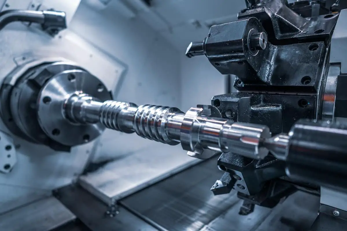
For CNC machine tools, achieving precise machining of parts relies on program codes controlling the machine tools, which can be obtained both manually and automatically.
Regardless of how these program codes are obtained, tool setting operations are required before machining.
Therefore, it is essential for machining personnel to understand the relationship between the machine tool coordinate system and the workpiece coordinate system, and how to accurately set the tools, to produce high-quality parts.
This paper summarizes methods and experiences in this area, which are worth referring to by peers.

The machine tool coordinate system, also known as the mechanical coordinate system, is established by the machine tool manufacturers to determine the positions of the workpiece, cutting tool, and others within the machine.
Upon startup, the machine typically locates the origin of the machine tool coordinate system automatically through homing or returning to the reference point. This system serves as the reference for all other coordinate systems.
The workpiece coordinate system, or programming coordinate system, is created to position the workpiece. It is established by the programmers based on the design drawings, used to identify the coordinate values of each base point on the part contour.
Understanding how to convert between the workpiece coordinate system and the machine tool coordinate system is crucial for the operator.
This article explores the tooling methods of CNC milling machines and machining centers, transforming the base point coordinates under the workpiece coordinate system to the machine tool coordinate system, thereby establishing the relationship between the two systems.
In CNC milling machines or machining centers, G54, G55, G56, G57, G58, G59 are typically used to store six different workpiece zero points.
During tooling, the tooling value can be input into any preset coordinate system. During machining, the corresponding system can be called up by inputting the stored offset quantity in the registers.
Given that CNC milling machines and machining centers involve the X, Y, and Z coordinate axes, each axis must be individually set during the tool setting process (note that the order of setting these axes is not significant).
The trial cutting method is the most frequently applied tool setting technique in practice.
The subsequent section illustrates the specific operational method using a FANUC CNC system milling machine as an example.
The workpiece coordinate system is established in the middle of the raw material.
Assuming the dimensions of the raw material to be 100X80X20, and all the surfaces of the raw material have been processed, the chosen tool size is φ20.
Since the projection of the tool during the tool setting is a circle, we represent the tool as a circle of φ20.
The alignment of the tool with the Y-axis requires the following steps: First, mount the workpiece on the workbench using a fixture, ensuring that all four sides of the workpiece leave room for tool alignment.
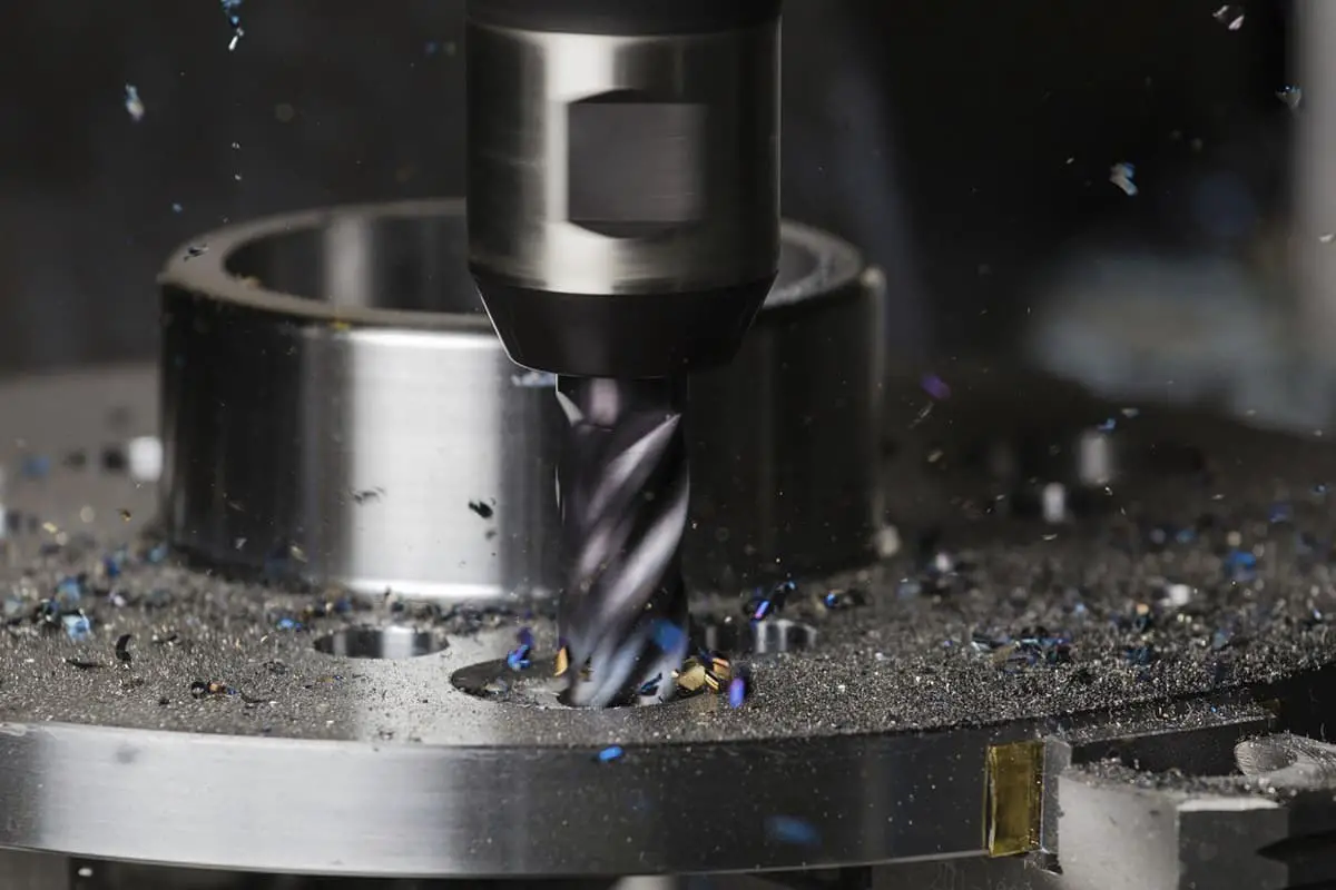
Second, rotate the tool at a certain speed and move the workbench manually or by hand cranking, bringing the tool closer to the left side of the blank. Move the spindle to reach the appropriate depth in the Z-direction.
Determine whether the tool is in contact with the left side of the blank by observing the metal chips or by listening to the cutting sound.
Without changing the position, enter the G54-G59 coordinate system interface through the OFFSET button on the control panel, taking the G54 coordinate system as an example.
Place the cursor at the corresponding X, input -(100/2+20/2)=-60, then click on measure, at this point, the X-axis alignment is complete. If the tool is close to the right side of the blank, the value to be input at this time is +60.
Similarly, by controlling the tool to touch the front or back of the blank, the tool alignment in the Y-axis direction can be achieved.
Z-Axis Tool Setting
The tool rotates, controlling the worktable and the main spindle to move quickly.
Once the tool moves to a position near the surface of the workpiece, maintaining a certain safety distance, the movement speed is reduced to make the bottom of the tool contact the surface of the workpiece.
At this point, the G54 coordinate system is invoked. Position the cursor to Z input 0, and click the corresponding soft key under the measurement to achieve Z-axis tool setting.
In this method of tool setting, the X-axis and Y-axis only need the tool to contact one side of the workpiece. However, during tool setting, it is necessary to know the dimensions of the workpiece and tool, hence it is suitable for regular workpieces.
Taking the previous workpiece as an example, because the Z-axis tool setting in this method is the same as the unilateral tool setting, we focus on the X-axis and Y-axis tool setting methods.
X-axis and Y-axis tool setting requires three steps:
1) By moving the spindle and the workpiece, let the tool touch the left side of the workpiece. Enter the relative coordinate interface through the POS button on the control panel, then input X.
At this point, the X coordinate on the screen begins to flash. Press the zero-return softkey corresponding to the bottom of the screen, and the X value displayed on the screen is now 0.
2) Retract the tool along the positive Z direction. Use manual and hand-crank methods to make the tool touch the right side of the workpiece. Observe and remember the X value displayed on the screen at this time (Note: The Y-axis direction remains stationary during movement).
3) Call out the G54 coordinate system, position the cursor to X, input “1/2 value” while retaining the original positive or negative sign (if it’s a positive sign, the sign can be omitted), then click the softkey under measurement to complete tool setting in the X direction.
Similarly, by controlling the tool to touch the front and back of the workpiece respectively, the tool setting for the Y-axis is achieved.
In this tool setting method, the tool needs to touch the left, right, front, and back of the workpiece for both X and Y axes.
However, there is no need to consider the size of the workpiece and the tool during tool setting, making it suitable for tool setting of both regular and irregular workpieces.
After completing the tool setting with any trial cutting method, to prevent wastage of the tool and blank due to tool setting errors, it is suggested to inspect the tool setting by inputting the command “G54 G90 G00 X0 Y0 Z100.” in MDI mode.
During operation, it is advised to turn the rate switch to the 0 position and press the cycle start button (in “auto” mode), then adjust the rate switch to a smaller value to let the tool run at a slower speed.
After executing this command, observe whether the tool has reached the designated position to verify the correctness of the tool setting.
Analyzing and exploring the tool setting methods of CNC milling machines and machining centers helps students to flexibly choose the appropriate tool setting method according to different blank shapes, thereby ensuring the machining accuracy of the parts.
Tool setting is an essential link in part machining, and there are many types of tool setting methods.
The methods introduced in this article are practical and straightforward, and there are many more accurate and convenient tool setting methods waiting to be developed and studied.

