A Comprehensive Guide to Linear Bearings: Everything You Need to Know
Have you ever wondered what the key to smooth, precise motion is in machines? Linear bearings are the unsung heroes behind countless automated systems, enabling effortless transfer, handling, positioning, and assembly. In this blog post, we’ll dive into the world of linear bearings, comparing them to other linear motion components and revealing their unique advantages. Get ready to discover how these marvels of engineering can revolutionize your designs!
1. Linear bearings and other linear motion guiding components
Linear motion guiding components are the most commonly used components in automated motion mechanisms for transfer, handling, positioning, and assembly.
Here, we will compare linear bearings, sliding guides, and oil-free bushings, and focus on the usage of linear bearings.
(1) Comparison of the features of linear bearings
A rough comparison of the features of the three linear motion guiding components is summarized in the table below.
Below is an introduction to the relation between the above features and the construction.
(2) The correlation between the characteristics and the construction of the linear guiding parts.
1. Performance differences with respect to load-carrying capacity:
Linear bearings and self-lubricating bushings.
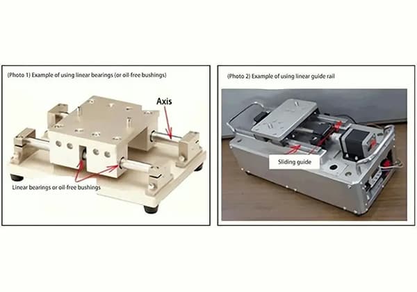
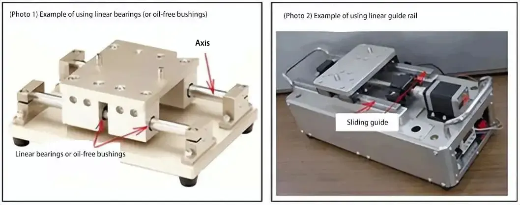
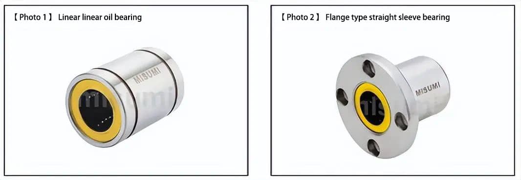
a) The movable components with linear bearings or self-lubricating bushings are generally assembled on a shaft (guide rail) supported by support structures at both ends to achieve their motion function. When carrying large loads, the shaft is easily deformed (see [photo 1]).
(Additionally, when vertically guiding linearly, a simple structure that ignores the load issue can be used as the shaft does not need to support the load of the moving component.)
Linear guides
b) The movable components move on the fixed guide rails mounted on the base, which has excellent load-bearing characteristics (see [photo 2]).
Linear bearings and self-lubricating bushings => Linear motion on a shaft (guide rail) fixed at both ends => linear motion with light to medium loads.
Linear guides => Linear motion on guide rails fixed to the base => linear motion with light to heavy loads.
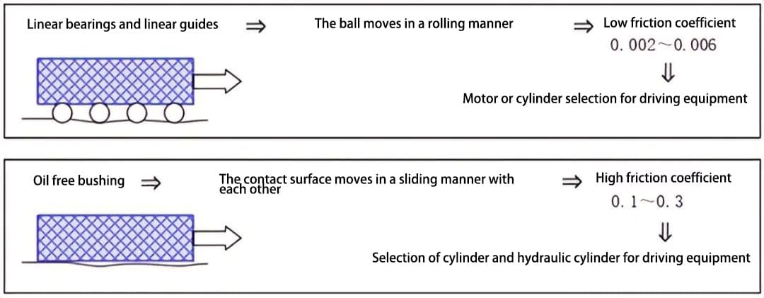
2. Performance differences with respect to friction coefficient:
Here, the differences in the guiding sliding method (rolling or surface sliding) determine the performance differences. The difference in the friction coefficient is directly related to the selection of the driving actuator.
a) Small frictional resistance = small frictional force = can be driven by a small torque motor = rotary motion can be converted into linear motion.
b) Large frictional resistance = large frictional force = requires large torque or thrust drive = can be directly driven by a linear cylinder.
■ Precautions for use
The size of the friction coefficient affects the ability of the drive equipment and the amount of heat generated during operation. Self-lubricating bushings are not suitable for continuous high-speed operation with high heat generation.
When using a cylinder, the initial/stop speed cannot be controlled as with a motor. High-speed operation and vibration suppression can be achieved by installing flexible braking mechanisms such as shock absorbers and dampers.
3. Performance differences with respect to guide precision:
Basically, the performance is determined by the gap between the bearing and the guide rail.
a) In the case of linear bearings, a cylindrical shaft is used as the guide rail, and the gap between the bearing and the guide rail is set to “interference fit: g6” or “transition fit: h5”, and the bearing slides in a state of minimal “gap”.
b) For linear guides, dedicated guide rails are used, and high-precision bearings and guide rails with small gap type (0-3 μm) or pressurized type (-3-0 μm) are paired.
c) Compared with linear bearings, the self-lubricating bushings have a larger gap between the guide rail (shaft), resulting in lower precision in guiding.
■ Precautions for use
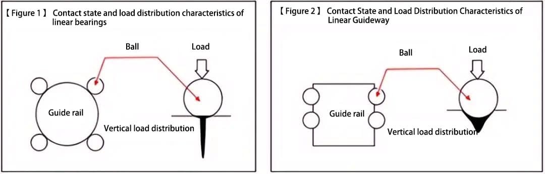
The contact states between the ball and guide rail are different for linear bearings and linear guides. The linear bearings have a point contact state, where the contact portion locally bears a large load.
The contact portion between the guide rail and ball bearing in the linear guides adopts a groove shape, allowing the ball to be in a surface contact state with the guide rail surface, and hence the contact load is dispersed.
There are also differences in the load-carrying capacity characteristics between the two with respect to the contact state in the sliding portion. ([Figure 1] and [Figure 2])
Linear bearings => point contact state => uneven vertical load distribution => not suitable for high load conditions.
Linear guides => surface contact state => dispersed vertical load distribution => can withstand relatively high loads.
4. About environmental resistance and maintainability:
This performance difference is determined by the differences in the constituent materials.
a) Linear bearings and linear guides can achieve long-term reliability due to the lubricating oil (grease) effect, so the working environment cannot exceed the environmental resistance index of the lubricating oil.
b) Self-lubricating bushings are generally used in environments where there is no lubricating oil, and have good environmental resistance and maintainability.
2. Distinction between linear and flanged types
Below, we explain the differences in the external shapes of linear bearings (linear type and flanged type) and the precautions to be taken during assembly.
(1) Linear type and flanged type of linear bearings
[Photo 1] shows the linear type, and [Photo 2] shows the flanged type.
The flanged type of [Photo 2] linear bearing has the following advantages:
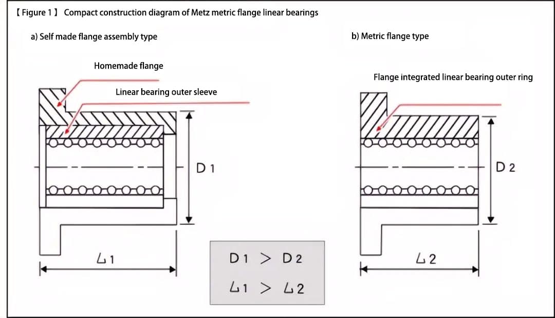
It has a more compact structure by adopting an integrated construction of a linear bearing and a flanged shaft sleeve ([Figure 1]).
Compared to a linear bearing combined with a separately produced flange, it has advantages such as low cost, short delivery time, and stable quality.
[Figure 1] is a schematic diagram explaining the compact structure of the flanged linear bearing. The assembly structure of the linear bearing with the flange and the shape of the shaft sleeve are too long, whereas the flanged linear bearing adopts an integrated structure, which is more compact. This compact design enables maintaining load-bearing performance.
(2) Distinguishing between Linear Types and Flange Types
Choose linear or flange types of bearings according to the following criteria: Select flange types of linear bearings if they are load bearing.
Choose based on the surrounding space and construction surfaces around the installation of the linear bearings. Refer to item (3) for installation methods and precautions regarding linear bearings.
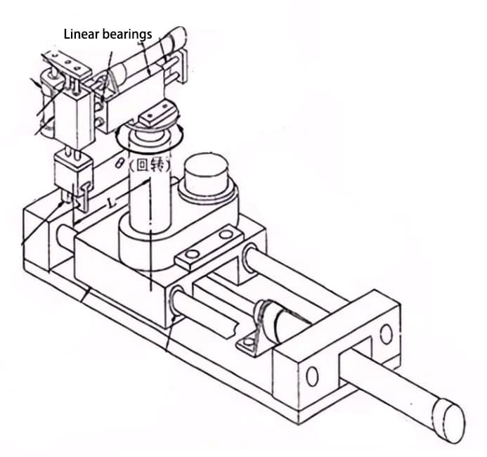
Linear bearings are divided into self-moving and axle-fixed types for shaft rotation. Figure 2 illustrates the construction of a X-Y-Z-θ driven platform with the shaft as the guiding axis. Bearings are classified accordingly.
a) X-axis: Linear bearings are self-moving and flange type.
b) Y-axis: Linear bearings are fixed (in the direction of the Θ-axis) and allow movement in the A-axis direction.
c) Z-axis: Linear bearings are fixed in the Z-axis direction and allow movement in the Y-axis direction.
For linear types, select snap ring or stopper plate fixing methods based on the desired strength of the fixing.
a) The X-axis movable part of the section is subject to the inertial force of the weight of the movable part supported by the linear bearing. The linear bearing needs to be tightly fixed.
b) The linear bearing is fixed to the bearing seat, and due to the use of a cylinder to drive the shaft structure, the linear bearing’s axial fixation only withstands the reaction force of friction, therefore a compact design was adopted for the linear type. In addition, the Y-axis linear bearings are set in the opposite direction to the two axes relative to the rotation axis of the θ driven platform, allowing for high rigidity in relation to the rotational torque.
c) If considering from the direction of the movable shaft, it is the same as b) and will not bear large forces.
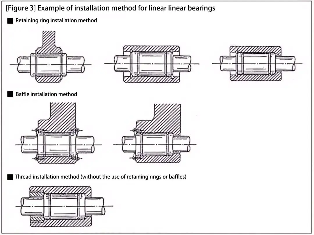
(3) Installation methods and precautions for linear bearings.
(1) Installation methods for linear bearings
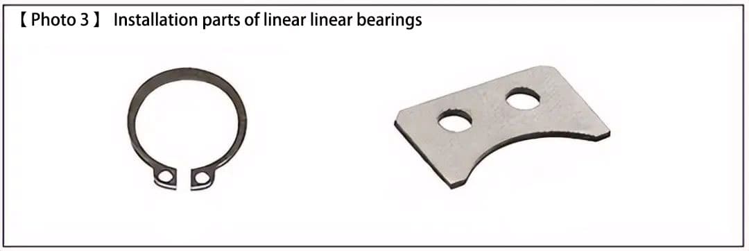
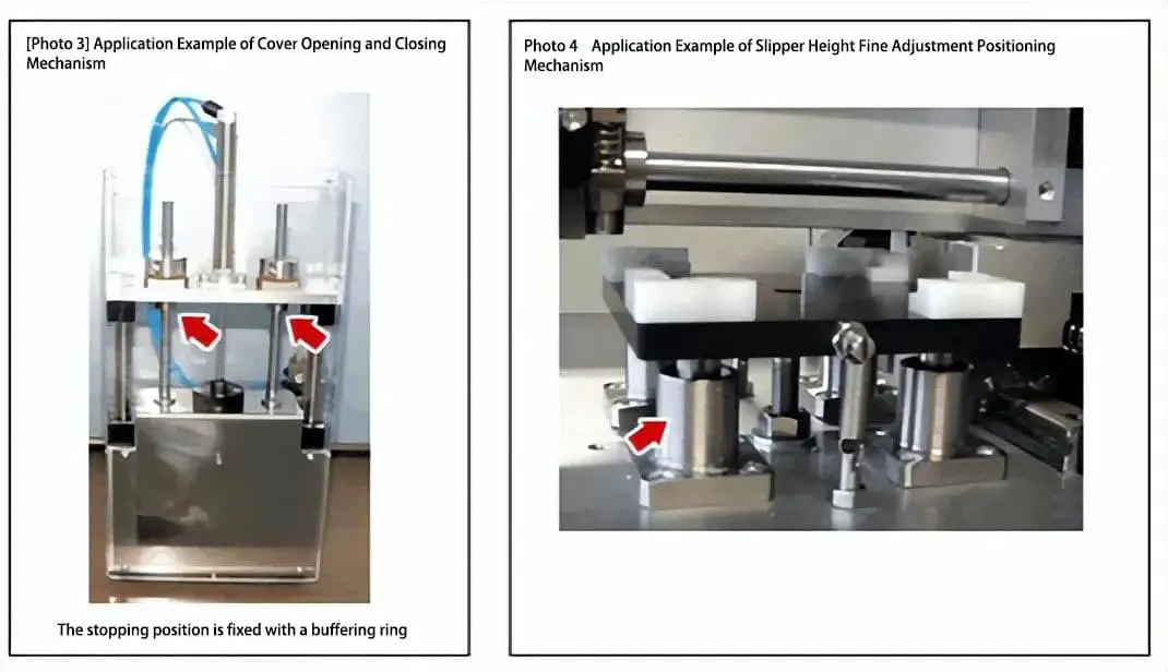
Linear bearings are generally installed using snap rings or stopper plates (refer to [Photo 3] and [Figure 3]).
(2) Precautions for the installation angle of linear bearings
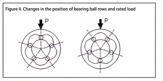
Due to differences in the shaft diameter and type, as well as the number of ball rows in the bearing, linear bearings generally have 4 to 6 rows of balls arranged at equal angles. When using linear bearings horizontally, avoid installing them with the ball rows in the position directly above (as shown in the left side of [Figure 4]) as this can result in concentrated loads.
[Figure 4] shows a 5-row ball bearing, and the ratio of rated load values are shown below (right side ÷ left side). Therefore, installation should be done as closely as possible to the installation angle shown in the above diagram.
Rating static load (Right side ÷ Left side) = 1.46
Rating dynamic load (Right side ÷ Left side) = 1.19
3. Differentiation of single-lined, double-lined, extended, and surface treated bearings.
(1) Bearing length and guiding performance
Linear bearings can be divided into four types based on bearing length:
[1] single-lined
[2] double-lined
[3] extended
[4] customer-designed (using two single-lined types).
The difference in bearing length directly affects the guiding performance as follows:
a) Load-bearing capacity
b) Guiding accuracy
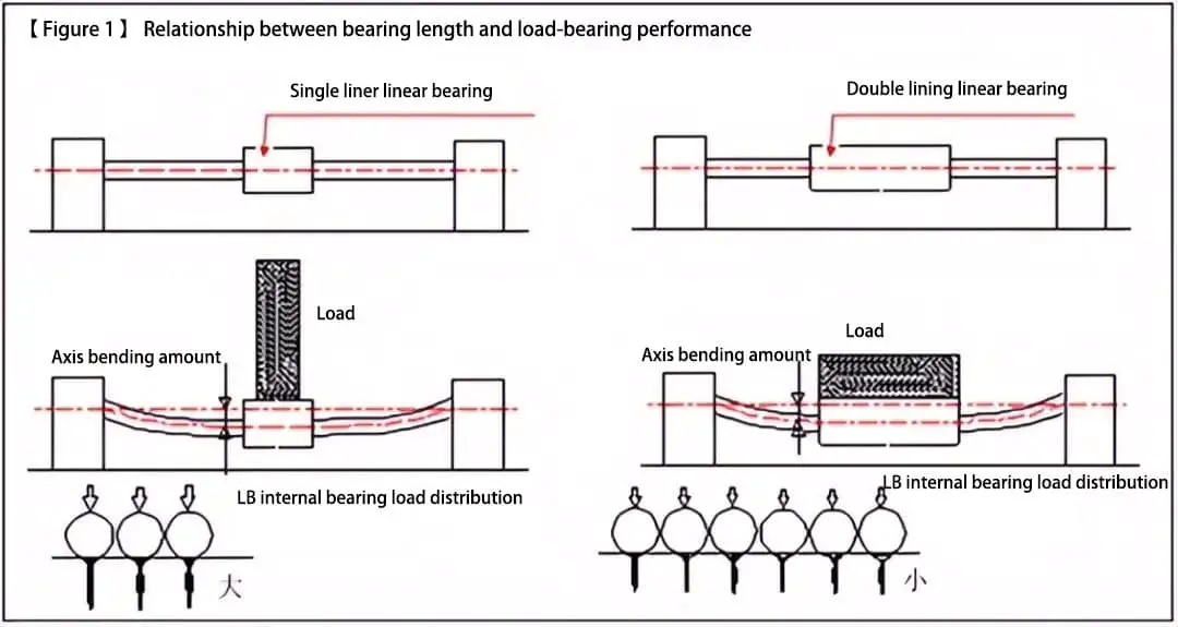
a) Relationship between bearing length and load-bearing capacity
The longer the bearing, the more supporting points there are, and the smaller the load required for each bearing contact point. This conclusion can be drawn from the actual situation where the rated load of the three types [1], [2], and [3] of linear bearings increases sequentially with their length.
Therefore, choosing a longer linear bearing length can improve the load-bearing capacity of the product (= lifespan and reliability increase) ([Figure 1]).
b) Relationship between bearing length and guiding accuracy
The longer the bearing length, the higher the guiding accuracy.
1)
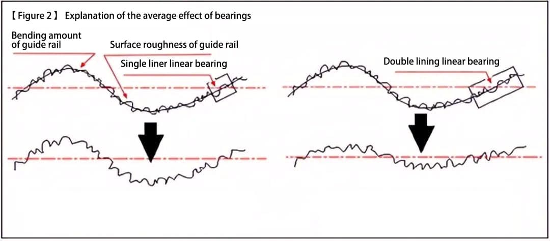
By averaging the guiding error of the guide rail (shaft), product accuracy can be improved (refer to the corresponding note for details) ([Figure 2]).
2)
Product accuracy can be improved by reducing the clearance error between the guide rail (shaft) ([Figure 3]).
The averaging effect of the bearings: By increasing the length of the linear guide bearing, the number of bearing supports is increased, and the error factors on the guide surface (surface roughness and bending deformation) can be averaged, with the effect of the error factor suppressed to less than half.
Therefore, by increasing the bearing length, load-bearing capacity and guiding accuracy can be improved.
Therefore, type [4] (which uses a dedicated design with two single-lined types) of linear bearing is often used in high-precision work environments to some extent ([Figure 4]).
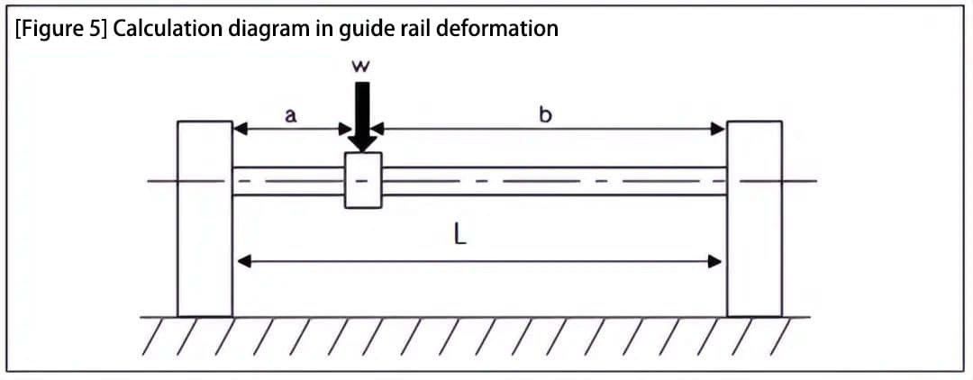
(2) Calculation of guide rail (shaft) deformation ([Figure 5])
In a linear mechanism composed of a linear bearing and a shaft, the deformation of the shaft can be calculated using the following equation:
δ = (W * a3 * b3) / (3 * E * I * L3)
where:
a: Distance from the support endpoint to the load position
b: Distance from the support endpoint on the opposite side of a to the load position
L: Distance between shaft supports
E: Young’s modulus
I: Second moment of area of the cross-section
I = πd4/64 ≈ 0.05d4
d: Shaft diameter
W: Load supported by the linear bearing (unit: N)
When a = b = L/2, δ = W * L3 / (9.6 * E * d4).
Therefore, if you want to reduce the shaft deformation, you should adopt a design approach that increases the shaft diameter (4 times the effect) or shortens the distance between shaft supports (3 times the effect).
(3) Characteristics and Application Examples of Component Materials and Surface Treatment
The constituent materials, surface treatments, and application examples of linear bearings are presented in the following table:
Outer Ring Material
Surface Treatment
Retainer Material
Ball Material
Application Examples:
SUJ2
–
Equivalent to Resin/SUS440C
SUJ2
Sliding guide with general wear resistance requirement.
Precision movement for optical components with no reflection in dust-free environment.
SUJ2
Chemical Ni-P
Same as above.
Same as above.
Chemical-resistant sliding parts in dust-free environment requiring wear resistance.
Equivalent to SUS440
–
Same as above.
Same as above.
Light load in dust-free environment and equipment used in food and medical fields.
Comparative Characteristics of Surface Treatments.
Outer Ring Material:
Surface treatment
Features:
SUJ2
–
SUJ2 is made of iron and is prone to rusting.
Same as above.
Low-temperature black chrome
Low friction coefficient and good wear resistanceCapable of forming a uniform, thin coating with black color that does not reflect light and exhibits good heat absorption.
Same as above.
Chemical plating of Ni-P
Excellent resistance to chemical agents and corrosion, often used in clean roomsHard coating with a glossy, non-magnetic finish.
4. Example of the Application of Linear Bearings on Simple Automatic Equipment
The features of linear bearings are described below:
Straightforward, low-cost guidance bearings with medium performance. (High cost-benefit ratio)
Low friction coefficient, making it easy to select the drive. (Low-cost cylinder or medium-priced motor type)
By combining it with a synchronous belt, a silent and lightweight driving construction design can be achieved.
In the case of vertical directional guidance, the use of the center-of-gravity driving method allows for a simple and compact construction design.
The usage and characteristics of linear bearings are explained below through an example of their application in simple automated equipment.
(1) Stepper motor and synchronous belt drive
The synchronous belt drive construction has advantages such as quietness, lightness, low cost and no need for oiling. For the X/Y/Z axis worktable situation, the usual design concept is to reduce the load on the lower X-axis motor by lightening the upper Y-axis.
Therefore, the Y-axis is often constructed using a synchronous belt.
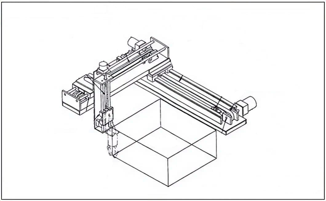
a) [Figure 1] shows a typical X/Y/Z 3-axis drive mechanism.
The X-axis is made of linear guides while the Y-axis and Z-axis are constructed using linear bearings. The drive system uses synchronous belts and ball screws.
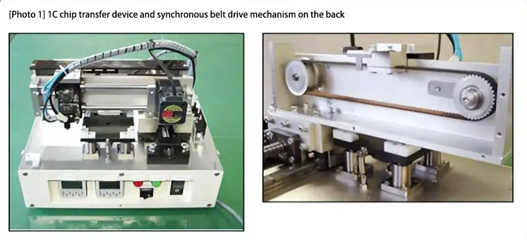
b) [Photo 1] shows an application example of the Y-axis in an IC chip mounting device. The Y-axis direction is converted into reciprocating motion by a synchronous belt.
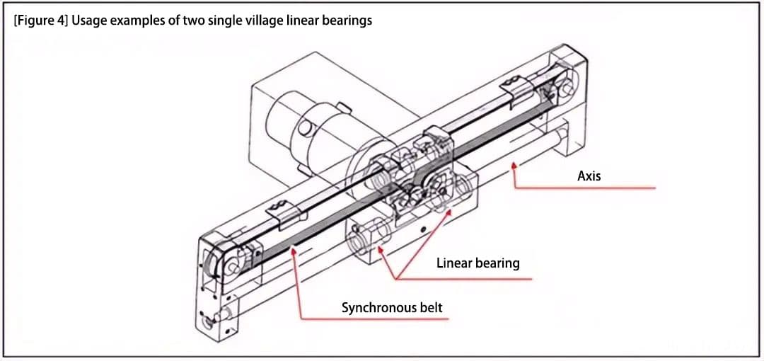
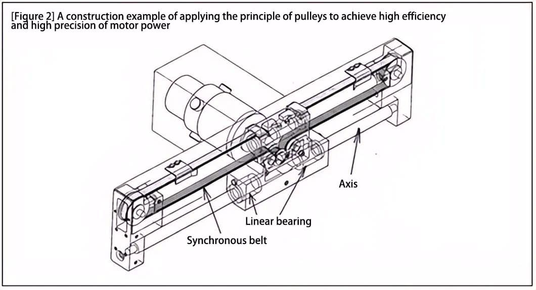
c) [Figure 2] shows an application example of a single-axis robot with the following features:
Two linear bearings are used with a large span to improve bearing capacity and guidance accuracy.
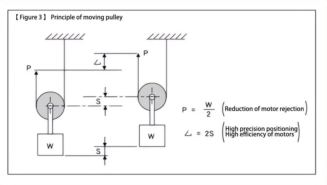
The design and structure of the synchronous belt and pulley use a rolling pulley principle ([Figure 3]) to achieve high efficiency of the motor power and high precision positioning.
The synchronous belt drive is lightweight and quiet.
The synchronous belt and shaft are arranged in parallel up and down, and even with a single-axis structure, the relative rotation between the shaft and the linear bearing can be restrained.
Principle of moving pulley:
To raise the lifting object in Figure 3 by a distance S, the rope lock needs to be moved twice the height, but the required force is only half of the weight of the lifting object, which can easily lift the lifting object.
2 times the moving distance
<1> Positioning accuracy that can improve the minimum resolution of motor rotation <2> Reduce the recoil and idle error of the pulley by half <3> High speed rotation (2x) drive of the motor, resulting in high motor efficiency
1/2 times the load
<4> It can be driven by a low-power motor (without the need for reduction gears, etc.)
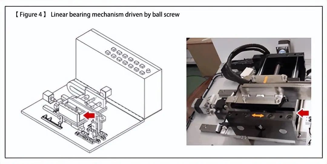
(2) Stepper motor and ball screw drive
The driving method of the ball screw has the following characteristics: [1] it directly converts the rotary motion of the motor into linear motion, and [2] the ball screw pitch has a function of a reducer. The transmission efficiency of the driving force and the motor efficiency are relatively high.
[Figure 4] is a driving mechanism in which the Y-axis uses a linear bearing and a ball screw. This is usually applied to mechanisms that require unit feed or have positioning accuracy requirements.
Additional Information:
a) Characteristics of a stepper motor
Stepper motors have the characteristic of producing high torque in the low-speed range (generally at start-up and deceleration), making them suitable for short distance movement and multi-point positioning control.
b) Necessary precision of the motor required for achieving target positioning accuracy
Target positioning accuracy = ±0.01 (mm). When selecting a ball screw lead of 10 (mm/rev), the necessary precision (divisions) of the stepper motor can be calculated using the following formula.
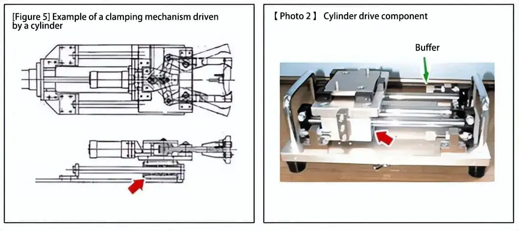
(3) Cylinder Drive
[Figure 5] is an example of a bearing used for cylinder drive in a clamp mechanism, while [Photo 2] is an example of a cylinder drive mechanism that uses a magnetic coupling. Both use linear bearings (indicated by the arrows) for guidance.
It is not possible to control the speed of starting and stopping with a cylinder drive, so a buffer must be used to reduce the impact when stopping (as shown in [Photo 2]).
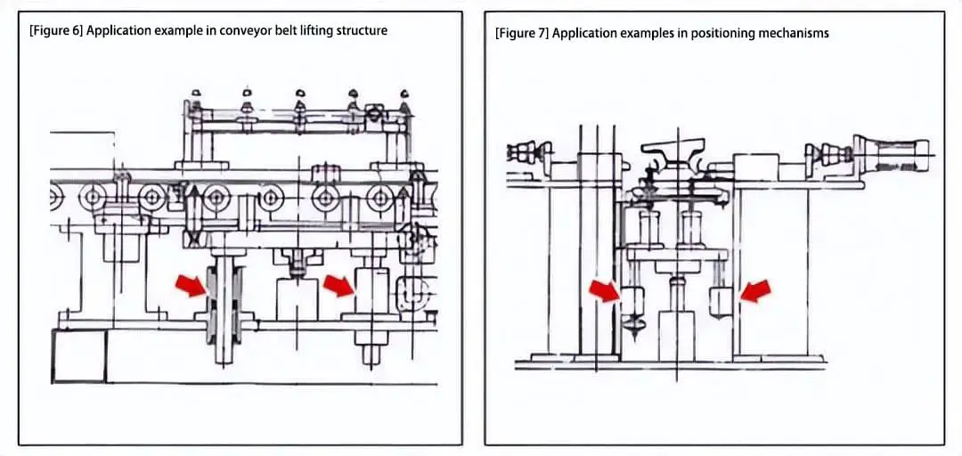
(4) Examples of vertical guidance
Vertical guidance can be achieved by using linear bearings with flanges. A specific support structure is not necessary for securing the installation of the linear bearings, which enables a simple and compact structural design (in the case of sliding guides, where a vertical mounting substrate must be set up for the fixed guide rail).
Similar to the structure in [Photo 4], the lifting guide (shown in [Figure 6]) and positioning mechanism (shown in [Figure 7]) for the lower part of the conveyor belt also use flanged linear bearings.
As the founder of MachineMFG, I have dedicated over a decade of my career to the metalworking industry. My extensive experience has allowed me to become an expert in the fields of sheet metal fabrication, machining, mechanical engineering, and machine tools for metals. I am constantly thinking, reading, and writing about these subjects, constantly striving to stay at the forefront of my field. Let my knowledge and expertise be an asset to your business.
Attention all mechanical engineers and manufacturing professionals! Are you struggling with pesky anodizing defects in your aluminum products? Look no further! In this blog post, we'll dive deep into the…
Ever wondered why some materials bend easily while others remain rigid? This blog dives into the fascinating world of elastic modulus and stiffness, unraveling their crucial roles in engineering. By…
Have you ever wondered what makes a perfect circle? In the world of mechanical engineering, roundness is a crucial concept that affects the performance and longevity of rotating components. This…
In today's fast-paced manufacturing world, efficient deburring is crucial. With numerous methods available, choosing the right one can be daunting. In this blog post, we'll explore various deburring techniques, from…
Have you ever wondered what keeps the world spinning smoothly? The unsung heroes behind the scenes are bearings. These small but mighty components play a crucial role in reducing friction…
Gears are the unsung heroes of the mechanical world, quietly working behind the scenes to keep machines running smoothly. But have you ever wondered what materials these critical components are…
This article explores the top 5 cooling tower manufacturers shaping our world. Learn how these companies innovate to keep industries running smoothly and efficiently. Get ready to uncover the secrets…
Have you ever wondered what keeps our gas systems running smoothly and safely? In this article, we explore top gas regulator manufacturers, uncovering their innovations and contributions to the industry.…
Ever wondered why connecting copper and aluminum wires is problematic? This article explains the risks associated with connecting these two metals due to their differing electrochemical properties, which can lead…