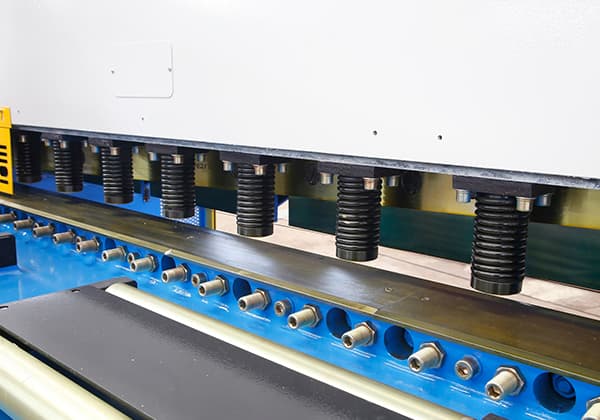
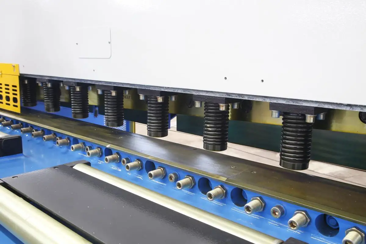
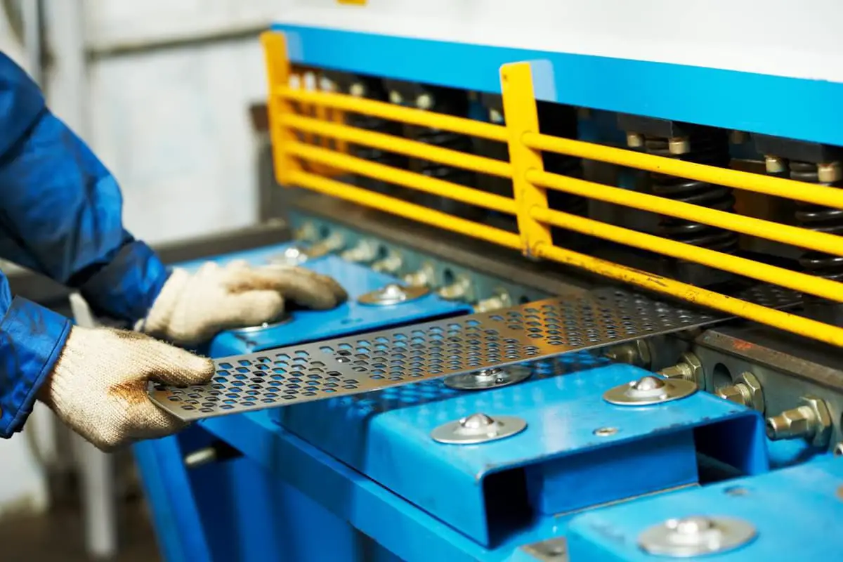
1. Remove the front worktable plate, front support arm, and protective cover
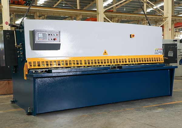
As shown in the picture:
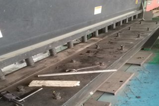
2. Blade removal
① When disassembling, remove the blade first. Leave one bolt in the middle of the blade loosened but not removed to prevent the blade from falling and causing injury. After removing all the bolts, two people should cooperate to lift the lower blade (you can screw two bolts onto the blade to make it easier for both people to lift).
② On the control panel, switch to “Manual Shaft Mode” (the third option, which can only be performed in stop mode) as shown in the picture:
- Rear stopper set greater than 900
- Change the upper blade cutting angle to 0.5° (the larger the angle, the greater the tilt of the upper blade)
- Adjust the clearance between the upper and lower blades to be greater than 0.5 (to prevent the blades from knocking against each other when installed)
3. Disassembling the upper blade
When disassembling, loosen the middle bolt without removing it. Then, loosen (counterclockwise) the pressure relief valve inside the device as shown in the picture:
When loosening the pressure relief valve, follow the principle of “better slow than fast.” The larger the counterclockwise rotation, the faster the upper blade will descend.
When the upper blade has lowered enough to reveal the two hidden bolts, close the pressure relief valve (tighten clockwise all the way).
Now, you can remove the bolts hidden on both sides of the upper blade. After removing these two bolts, start the device’s oil pump, and the upper blade will return to the dead point, making it possible to remove the upper blade (you can adjust the tilt angle of the upper blade to be larger for easier disassembly).
During disassembly, multiple people should cooperate, using wooden planks in the middle to support the blade and prevent injury.
4. Clean the oil and dust
Clean the oil and dust on the upper and lower blades, inspect the condition of tool damage, and mark the usable surfaces in preparation for installation.
5. Blade installation
The installation steps are the reverse of the disassembly steps.
First, install the upper blade by slightly securing it with two bolts, making it easier for two people to lift and install.
Fasten the bolts to the device, and then install the lower blade (tighten it by hand until it cannot be turned further; the hidden bolts on both sides of the upper blade do not need to be installed yet).
Finally, on the control panel, switch to the third option, “Manual Shaft Mode,” and set the values: rear stopper at 900 or higher, cutting angle at 1.7° (greater than 1.5°), and clearance at 0.5 (to prevent the upper and lower blades from knocking against each other during installation).
6. Securing upper and lower blades
During the securing process, one person must always control the pressure relief valve, ensuring the descent of the upper blade is slow. When the upper blade is about to overlap with the lower blade, close the pressure relief valve.
Use a feeler gauge to check the clearance between the upper and lower blades; under normal circumstances, a 0.5mm feeler gauge should pass through (since the set clearance is 0.5mm).
If the clearance is too small (e.g., 0.1 or 0.2), it must be adjusted again in “Manual Shaft Mode.”
If the clearance is acceptable, it indicates that there will be no knocking between the blades, and you can continue to loosen the pressure relief valve. Close the valve (clockwise) again when the rightmost part of the upper blade is about to touch the lower blade.
Once more, use the feeler gauge to measure the clearance to prevent the blades from knocking due to insufficient clearance.
Start the oil pump to raise the upper blade slider to the dead point position. Use a wooden plank to support the middle of the upper and lower blades. Slowly loosen the pressure relief valve, allowing the blades to fully press against each other.
Tighten the nearby bolts and use the same method to gradually tighten the bolts on the upper and lower blades, moving from left to right in segments.
After tightening all the bolts, lower the upper blade and tighten the last two hidden bolts (which are shorter in length).
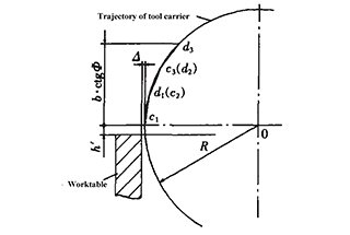
7. Clearance adjustment
Use a feeler gauge to calibrate the clearance on both sides of the upper and lower blades, checking if it matches the machine’s display. If not, adjustments are necessary. Follow these steps:
① Two people need to use adjustable wrenches: one person holds the hexagonal rod in place while the other loosens the nuts on both ends of the hexagonal rod, as shown in the picture:
Send the nuts on both ends to the top, and then use a wrench to rotate the hexagonal rod (adjustment rod). Rotating the rod clockwise will lower the screw and decrease the clearance, while counterclockwise rotation will raise the screw and increase the clearance (adjust according to the on-site situation).
② Use this method to adjust the clearance on both sides. The clearance should be adjusted to match the machine’s display, and it must be consistent on both sides of the upper and lower blades before tightening the nuts on both ends of the screw.
8. Verify the rear stopper size
After adjusting the clearance, verify whether the rear stopper’s size is correct. If there is an error, adjustments are necessary. Follow these steps:
① Move the rear stopper back (the machine display should show 900mm). Loosen nut “A” and then nut “C.” Use a wrench to twist the adjustment screw at point “B.” One full rotation of the screw is approximately 2.3mm (clockwise for reduction, counterclockwise for expansion).
② Once the rear stopper is adjusted, first tighten nut “A” and then nut “C.” Check the adjustment accuracy by cutting test pieces and continue making adjustments until the test pieces are satisfactory.