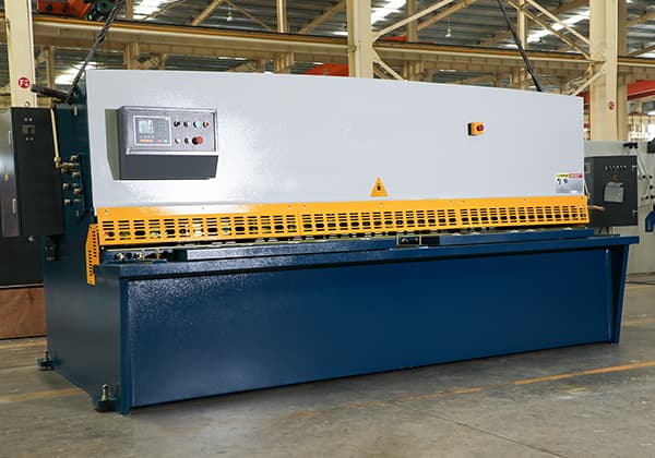
Have you ever wondered how those massive steel plates are cut with such precision? Enter the world of hydraulic shearing machines – the unsung heroes of the metal fabrication industry. In this blog post, we’ll dive into the fascinating mechanics behind these powerful machines and explore how they shape the world around us, from ships to skyscrapers. Get ready to be amazed by the sheer force and finesse of hydraulic shearing technology!
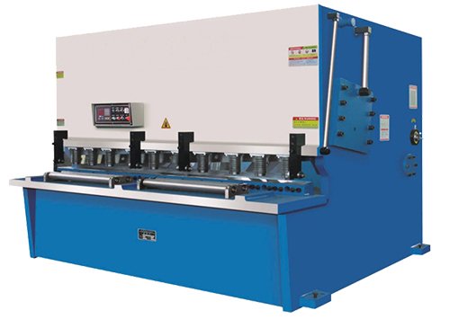
A hydraulic shearing machine is a specialized piece of equipment designed to cut metal plates with precision. It operates by using a moving upper blade and a fixed lower blade to apply a shearing force to metal plates of varying thicknesses. This process results in the separation of the metal plates into desired sizes, achieved by utilizing an appropriate blade clearance.
Key Features and Functionality
Blade Mechanism: The machine consists of an upper blade that moves vertically and a lower blade that remains stationary. The shearing action occurs when the upper blade descends, cutting through the metal plate positioned on the lower blade.
Hydraulic System: The movement of the upper blade is powered by a hydraulic system, which provides the necessary force and control for precise cutting. This system ensures smooth and consistent operation, allowing for the processing of various metal thicknesses.
Blade Clearance: The gap between the upper and lower blades, known as blade clearance, is adjustable. Proper blade clearance is crucial for achieving clean cuts and minimizing material deformation. The clearance is set based on the thickness and type of material being processed.
Applications in Various Industries
Hydraulic shearing machines are a type of forging machinery primarily used for metal processing. They are widely utilized across multiple industries due to their versatility and efficiency. Some of the key industries that benefit from hydraulic shearing machines include:
Aviation: For cutting metal sheets used in aircraft manufacturing and maintenance.
Light Industry: In the production of consumer goods and small-scale manufacturing.
Metallurgy: For processing raw metal materials into usable forms.
Chemical Industry: In the fabrication of equipment and containers used in chemical processing.
Construction: For cutting metal components used in building structures.
Shipbuilding: In the construction and repair of ships, where large metal plates need to be precisely cut.
Automobile: For manufacturing car body parts and other components.
Electric Power: In the production of electrical infrastructure components.
Electrical Appliances: For creating metal parts used in household and industrial appliances.
Decoration: In the fabrication of decorative metal elements for architectural purposes.
Hydraulic shearing machines play a crucial role in modern industrial production, providing precise and efficient metal cutting capabilities. Their widespread use across various industries highlights their importance in manufacturing and processing operations. By understanding the functionality and applications of these machines, industries can optimize their production processes and achieve high-quality results.
For a visual demonstration of a hydraulic shearing machine in action, please refer to the provided video below.
What is Hydraulic Shearing Machine?
A hydraulic shearing machine is a type of industrial equipment used for cutting metal sheets and plates. It operates using a hydraulic system to generate the necessary force for shearing. This machine is widely utilized in various industries due to its precision, efficiency, and ability to handle different thicknesses of metal materials.
Key Components and Functions
Hold-Down Cylinder:
The hold-down cylinder is powered by the hydraulic system to clamp the metal sheet securely in place during the cutting process. This ensures that the material does not move, leading to precise and clean cuts.
Left and Right Oil Cylinders:
These cylinders control the movement of the blade. They drive the blade carrier up and down, enabling the cutting action. The synchronization of these cylinders is crucial for maintaining the accuracy of the cut.
Blade Carrier and Blades:
The upper blade is mounted on the blade carrier, while the lower blade is fixed on the blade holders. The blades are positioned with a suitable clearance between them, which is adjustable based on the thickness of the metal sheet being cut. This clearance is essential for applying the correct shear force to achieve a clean cut without damaging the material.
Applications
Hydraulic shearing machines are used in a variety of industries due to their versatility and efficiency. Some of the key sectors include:
Steel Production: Cutting steel sheets and plates to specific sizes for further processing.
Shipbuilding: Fabricating metal components for ship structures.
Automobile Manufacturing: Producing parts and panels for vehicles.
Container Production: Creating metal containers and enclosures.
Electrical Switch Appliances: Manufacturing components for electrical devices.
Machinery Manufacturing: Producing parts for various types of machinery.
Light Industry: Cutting metal sheets for consumer goods and other light industrial applications.
Advantages
Precision: Hydraulic shearing machines offer high precision in cutting, which is essential for applications requiring tight tolerances.
Efficiency: These machines can handle large volumes of material quickly, making them ideal for industrial production.
Versatility: They can cut a wide range of metal materials and thicknesses, providing flexibility in manufacturing processes.
Safety: Modern hydraulic shearing machines are equipped with safety features to protect operators and ensure safe operation.
Working Principle of Hydraulic Shearing Machine
The hydraulic shearing machine operates on the principle of shear cutting, where sheet metal is cut by the relative motion of two blades. The process is driven by a hydraulic system that provides the necessary force and controlled movement. Here’s a more detailed explanation of the working principle:
Hydraulic Power Unit: The machine’s operation begins with a hydraulic power unit, which consists of an electric motor, a hydraulic pump, and a fluid reservoir. This unit generates and maintains the hydraulic pressure required for the shearing action.
Upper and Lower Blades: The machine features two primary cutting components – an upper blade (also called the ram) and a lower blade (often stationary). The upper blade is movable and attached to hydraulic cylinders.
Blade Movement: When activated, the hydraulic system drives the upper blade downward in a controlled manner. The movement is typically guided by precision linear bearings to ensure accuracy.
Shearing Action: As the upper blade descends, it comes into contact with the sheet metal positioned on the lower blade. The continued downward force causes the metal to deform plastically and eventually separate along the cutting line.
Blade Clearance: The gap between the upper and lower blades, known as the blade clearance, is crucial for clean cuts and is typically adjustable based on the material thickness and type.
Hold-Down Mechanism: Many hydraulic shears incorporate a hold-down system that secures the workpiece during cutting, preventing distortion and ensuring a straight cut.
Blade Return: After completing the cut, the hydraulic system retracts the upper blade to its original position, readying the machine for the next operation.
Control System: Modern hydraulic shearing machines often feature computerized control systems that allow for precise adjustment of cutting parameters, such as blade gap, cutting angle, and stroke length.
This hydraulic-driven process enables the shearing machine to deliver high cutting forces with precise control, making it suitable for a wide range of sheet metal thicknesses and materials.
Different Types of Hydraulic Shearing Machines
Shearing machines are essential tools in the metalworking industry, used to cut sheet metal and other materials. They can be broadly classified into two main types: hydraulic shears and mechanical shears. Hydraulic shearing machines are more commonly used due to their lower energy consumption and reduced noise compared to mechanical shears.
Classification of Hydraulic Shearing Machines
Hydraulic shearing machines can be further categorized based on the movement of the blade carrier:
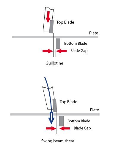
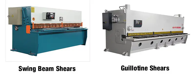
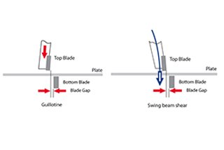
Hydraulic Swing Beam Shears: In these machines, the upper blade carrier swings around a pivot point.
Hydraulic Guillotine Shears: These machines use a linear motion to move the upper blade down in a straight path.
Types of Shearing Machines
Here is a detailed list of various types of shearing machines, along with their specific characteristics:
Guillotine Shear, Plate Shear: Utilizes a reciprocating linear motion between two blades to cut sheet metal.
Hand Guillotine Shear, Hand Plate Shear: Manually operated shears, suitable for small-scale or precise cutting tasks.
Hydraulic Guillotine Shear, Hydraulic Plate Shear: Operated by a hydraulic system, providing more power and precision.
Pivot Blade Shear, Swing Beam Shear: Features an upper blade carrier that swings around a pivot.
Hydraulic Pivot Blade Shear, Hydraulic Swing Beam Shear: Swing beam shears powered by a hydraulic system, combining the benefits of hydraulic power with the pivoting action.
Multi-Strip Slitter, Coil Slitting Shear: Uses multiple disc scissors to cut a coil into strips of the desired width.
Multi-Band Slitter, Sheet Slitting Shear: Similar to the coil slitting shear but used for cutting metal plates into strips.
Nibbling Machine: Processes plates into any desired shape through a step-by-step method, ideal for intricate cuts.
Circular Shear, Rotary Shear: Uses a pair of rotary blades to cut plates in straight or curved lines.
Universal Ironworker for Punch, Bar and Section Shear: A versatile machine that can punch and cut bars and sections.
Universal Ironworker for Plate and Section Shear: Combines the functions of metal plate punching and cutting.
Universal Ironworker for Punch, Plate, Bar and Section Shear: Offers three functions: plate punching, plate shearing, and section shearing.
Universal Ironworker for Punch, Plate, Bar and Section Shear, Notching: Adds a fourth function, notching, to the capabilities of the universal ironworker.
Bar Shear: Designed specifically for cutting bar materials.
Alligator Shear: Features an upper blade that moves in a scissor motion, resembling an alligator’s jaws.
Reinforcing Bar Shear: Specially designed for cutting reinforcing bars used in construction.
Precision Bar Shear: Provides precise shearing of bars, essential for high-accuracy applications.
Slab Shear: Designed for cutting large slabs of metal.
Scrap Shear: Used for cutting scrap steel, aiding in recycling processes.
Ingot Shear: Specially designed for cutting billets, which are large blocks of metal.
Hydraulic shearing machines offer a range of options to suit various industrial needs, from simple manual operations to complex, multi-functional machines. Understanding the specific types and their applications can help in selecting the right machine for a given task, ensuring efficiency and precision in metalworking operations.
Advantages of Hydraulic Shearing Machine
Hydraulic shearing machines offer several advantages over traditional plate shears, making them a preferred choice in modern industrial applications. Here are some key benefits:
1. Precision and Control
Numerical Control (NC): One of the most significant advantages of hydraulic shearing machines is their ability to be controlled by numerical codes. These codes are generated through various combinations of characters based on specific work requirements. This numerical control allows for precise management of the machine’s orientation, speed, and cutting force.
Accurate Positioning: Hydraulic shearing machines excel in positioning accuracy. The adjusting rod can rotate continuously around the central axis without dead angles, ensuring precise cuts. This feature is particularly beneficial for complex and repetitive tasks.
2. Operational Efficiency
Quiet Operation: Unlike traditional mechanical shears, hydraulic shearing machines operate quietly. This reduces noise pollution in the workplace, contributing to a more pleasant and healthier environment for operators.
Ease of Use: The operation of hydraulic shearing machines is straightforward and easy to learn. Operators primarily need basic computer skills to manage the machine, thanks to its user-friendly interface and automated controls.
3. Durability and Stability
Material Quality: These machines are typically constructed from durable stainless steel, which offers strong corrosion resistance and stability. This makes them suitable for environments with high vibration amplitudes and harsh conditions.
Robust Design: The robust construction of hydraulic shearing machines ensures long-term reliability and minimal maintenance requirements, further enhancing their operational efficiency.
4. Safety Features
Self-Defense Fence: Safety is a critical consideration in industrial machinery. Hydraulic shearing machines are equipped with sturdy self-defense fences that protect operators. In the event of a machine failure, the fence acts as a barrier, preventing direct contact between the operator and the machine.
Enhanced Visibility: The adjustment of lighting in hydraulic shearing machines improves visibility, allowing operators to quickly and accurately position the material. This feature adds convenience and safety to the production process.
5. Aesthetic and Functional Design
Sleek Appearance: In addition to their functional benefits, hydraulic shearing machines often feature a sleek and modern design. This not only enhances the aesthetic appeal of the workspace but also reflects the advanced technology and precision engineering behind the machine.
Versatility: Hydraulic shearing machines are highly versatile, capable of handling a wide range of materials and thicknesses. This makes them suitable for various industrial applications, from automotive to aerospace manufacturing.
Hydraulic shearing machines represent a significant advancement over traditional plate shears, offering precision, efficiency, durability, safety, and aesthetic appeal. Their ability to be controlled through numerical codes, combined with their robust construction and user-friendly operation, makes them an invaluable asset in modern manufacturing environments.
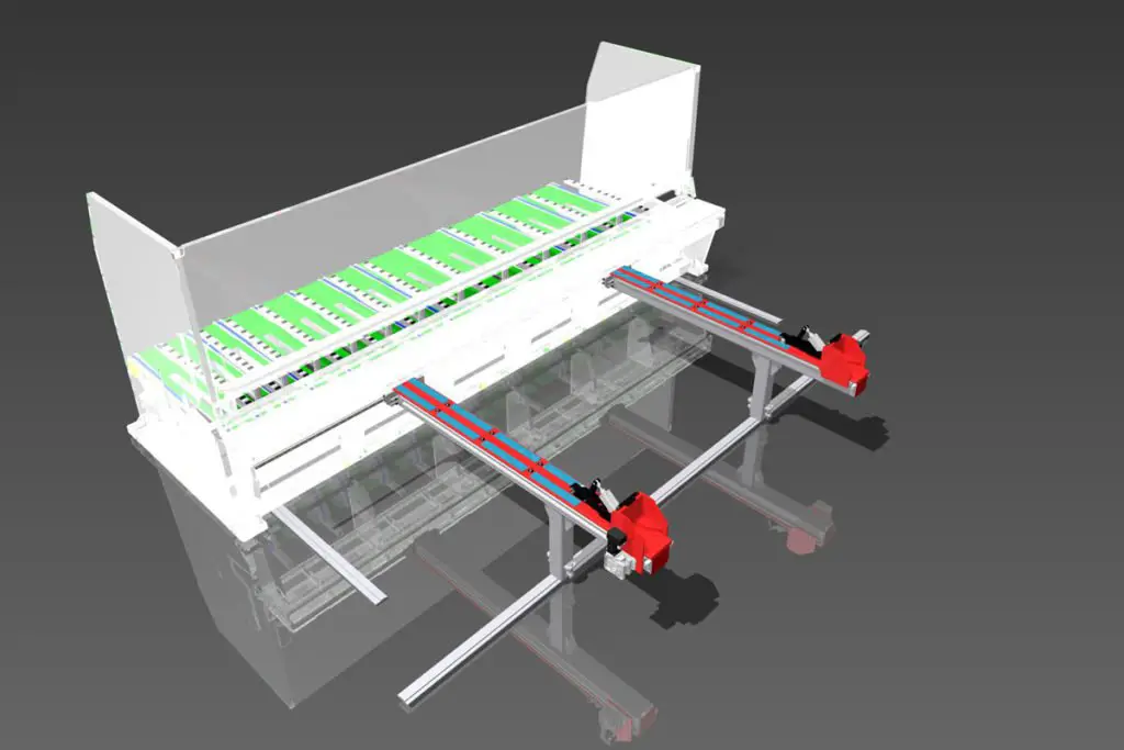
Parts and Function of Hydraulic Shearing Machine
Hydraulic shearing machines are essential in the metalworking industry for cutting sheet metal with precision and efficiency. Understanding the various components and their functions is crucial for optimal operation and maintenance. Below is a detailed overview of the main parts and functions of a hydraulic shearing machine.
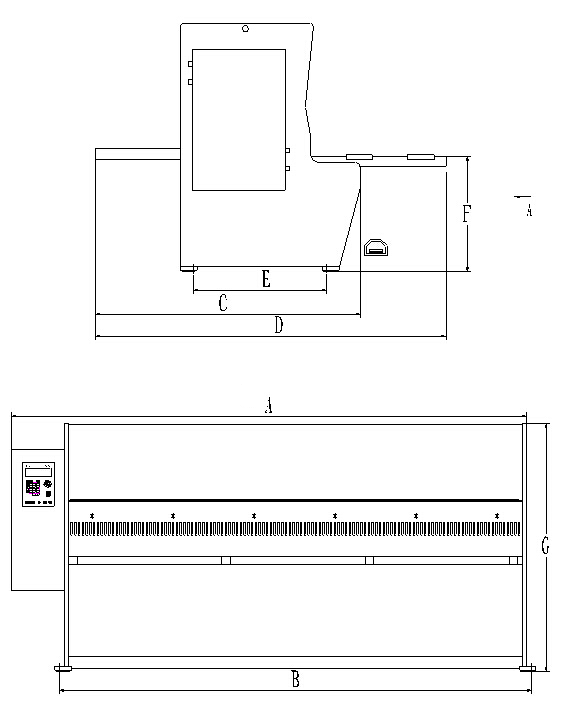
Shearing Machine Frame
The frame of the shearing machine is a robust structure constructed from steel plates, ensuring stability and durability. It includes several key components:
Left and Right Board: These provide structural support to the machine.
Worktable: The surface where the metal sheet is placed for cutting.
Clamp Holder: Holds the sheet metal in place during the shearing process.
Fuel Tank: Contains hydraulic oil necessary for the machine’s operation.
Additionally, hydraulic cylinders and sliding block guide supports are installed on both sides of the frame. These components act as a push-up mechanism to control the clearance of the blades, ensuring precise cuts.
Blade Holder
The blade holder is a critical component that houses the upper blade. It is connected to the hydraulic cylinder, allowing for vertical movement to transmit shear force and perform cutting. The blade holder also includes the backgauge mechanism, which accurately positions the size of the sheared plate.
Shear Blade
The shear blades are made from high-standard steel and are designed to cut various types of steel sheets, from low carbon to stainless steel. Both the upper and lower blades feature four interchangeable cutting edges, which can be rotated to extend the lifespan of the blades.
Backgauge Mechanism
The backgauge mechanism is essential for precise cut-to-length operations. It includes:
Backgauge Regulating Motor: Drives the movement of the backgauge.
Micro Dynamic Adjustment Mechanism: Allows for fine adjustments.
Backgauge Lifting Mechanism: Adjusts the height of the backgauge.
Digital Display Device: Shows the current settings and measurements.
Transmission Screw and Guide Bar: Ensure smooth and accurate movement of the backgauge.
Fuel Tank
The fuel tank is mounted on the oil tank base behind the shearing machine. It houses:
Hydraulic Integrated Valve Block: Controls the flow of hydraulic oil.
Hydraulic Oil Pump: Circulates the hydraulic oil.
Main Motor: Powers the hydraulic system.
An oil gauge on the left side of the tank indicates the hydraulic oil level, which should be maintained at the middle level for optimal performance.
Clearance Adjustment Device
This device allows for the adjustment of the gap between the upper and lower blades to match the thickness of the material being cut. Proper clearance adjustment is crucial for optimizing shear force, extending blade lifespan, and ensuring high-quality cuts. The general rule is to set the gap to 10% of the material thickness.
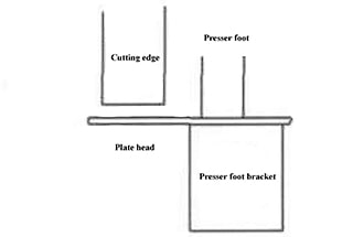
Front Supporter
The front supporter includes a side retaining device attached to the worktable, ensuring that the sheared plate remains perpendicular on both sides, which is essential for accurate and straight cuts.
Finger Protection Plate
Safety is paramount in operating a shearing machine. The finger protection plate is installed on the machine clamp holder to maintain a safe distance between the operator’s fingers and the cutting blades. This plate must meet mechanical safety standards to prevent accidents.
Understanding the parts and functions of a hydraulic shearing machine is vital for its efficient and safe operation. Each component plays a specific role in ensuring precise cuts, maintaining blade longevity, and protecting the operator. Regular maintenance and proper adjustment of these components will enhance the machine’s performance and extend its service life.
Safe distance for fingers protection
Shears
max.A
min.B
8/6.5/3000
12
80
8/6/4000
12
80
10/3000/4000
20
120
13/3000
23
200
Note: These dimensions comply with mechanical safety standards.
When positioning the plate in the backstop block, it is crucial to avoid placing your fingers between the plate and the shearing machine table. Failure to do so could result in the plate pressing against your fingers during the pressing process, leading to severe injuries.
Additionally, if the backgauge block is not in position, do not push the plate through the finger protection plate. This precaution helps prevent potential finger injuries.
Hold down Cylinder
The hold-down cylinder is essential for preventing plate movement during the cutting process. It firmly presses the plate to ensure stability and accuracy, thereby enhancing the quality of the cut and maintaining operator safety.
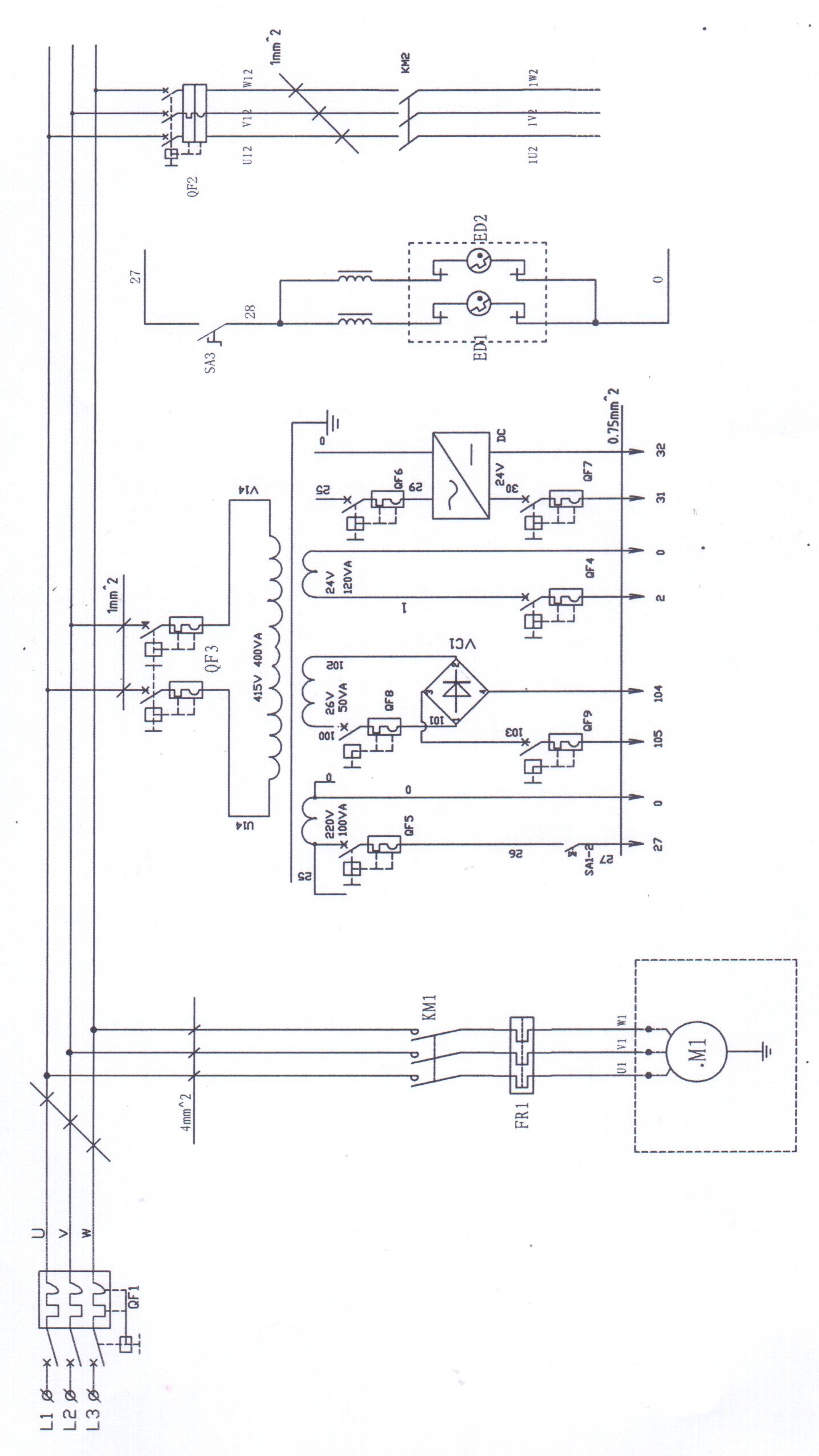
Electrical System of the Shearing Machine
The electrical system of a shearing machine is designed to perform several critical functions:
Power Supply and Control: The primary purpose is to start the oil pump motor, which drives the oil pump to provide hydraulic power for the shearing machine.
Control Circuit: This circuit connects the solenoid valve and oil pressure based on operating instructions. It drives the blade carrier’s up-and-down movement to achieve the cutting goal.
Additional Controls: Electricity is also used to control the stroke of the blade, back-and-forth movement, alignment of the cutting line, adjustment of the gap, and the shearing angle.
Hydraulic System of the Shearing Machine
The hydraulic system is a complex assembly of various components that work together to perform the cutting operation. It includes:
Main Oil Pump: Provides the necessary shearing pressure for the hydraulic equipment.
Hydraulic Components: These include the hydraulic cylinder, pressure cylinder, and hydraulic pipes, which control the system pressure and the direction of hydraulic oil flow.
Hydraulic Cylinder: Drives the blade holder movement to perform plate cutting.
Hold-Down Cylinder: Primarily presses the workpiece to ensure accuracy during the cutting process.
The hydraulic system’s precise control of pressure and flow direction is critical for the efficient and accurate operation of the shearing machine. These revisions ensure that the article is not only accurate and professional but also provides clear and detailed information that can be easily understood by readers, enhancing its overall quality and value.
Specifications of Hydraulic Shearing Machine
1. Shear Thickness
The maximum thickness that a hydraulic shearing machine can shear is primarily determined by the strength of the shearing mechanism and the shear force it can generate. Several factors influence the shear force, including:
Edge Clearance: The gap between the upper and lower blades.
Edge Sharpness: The condition of the cutting edges.
Shear Angle: The angle at which the blade cuts through the material.
Shear Speed: The rate at which the shearing action occurs.
Shear Temperature: The temperature of the material being sheared.
Width of the Sheared Surface: The dimension of the material in contact with the blades.
Material Strength: The inherent strength of the material being sheared.
Typically, hydraulic shearing machines can handle shear thicknesses up to 32mm. Beyond this thickness, the process becomes less cost-effective and efficient.
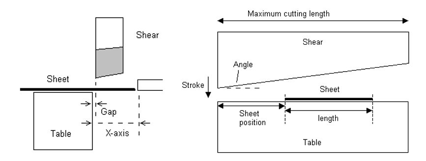
2. Shear Sheet Width
The shear sheet width refers to the maximum width of the metal sheet that can be cut in one pass by the shearing mechanism. This width is determined by the length of the cutting edge and the manufacturer’s specifications.
Cross-Cutting: This method involves cutting across the width of the sheet.
Slitting: This involves multiple parallel cuts along the length of the sheet.
As long as the strip width is less than the throat depth of the shearing mechanism, there are no significant limitations on the size. With technological advancements, hydraulic shearing machines now offer plate cutting widths up to 6000mm, with some foreign models reaching up to 10,000mm.
3. Shear Angle
To minimize bending and distortion in the sheared sheet metal, a smaller shear angle is generally preferred. While this increases the shear force required, it enhances the quality of the cut. However, the increased shear force can impact the strength and stiffness of the shearing mechanism’s stressed components.
4. Throat Depth
The throat depth is crucial for longitudinal cutting methods. A smaller throat depth improves the stiffness of the frame but may reduce the overall quality of the machine. The trend in modern hydraulic shearing machines is to optimize throat depth to balance stiffness and cutting quality.
By understanding these specifications, users can select the appropriate hydraulic shearing machine for their specific needs, ensuring efficient and high-quality metal cutting operations.
Applications of Hydraulic Shearing Machines
Hydraulic shearing machines are versatile tools extensively utilized across various industries due to their precision, efficiency, and ability to handle a wide range of materials. Below are some of the key applications of hydraulic shearing machines in different sectors:
Decoration Industry
In the decoration industry, hydraulic shearing machines are often used in tandem with bending machines to create stainless steel doors and windows. These machines help in cutting metal sheets to precise dimensions, which are then bent and shaped to form decorative elements for special places, enhancing both functionality and aesthetic appeal.
Electrical and Electric Power Industries
Hydraulic shearing machines play a crucial role in the electrical and electric power industries. They are employed to cut metal plates into specific sizes, which are then further processed using bending machines. This process is essential in the manufacturing of electrical cabinets, refrigerator panels, and air conditioning shells. The precision cutting ensures that the components fit together seamlessly, maintaining the integrity and safety of the electrical appliances.
Automobile and Shipbuilding Industries
In the automobile and shipbuilding industries, large hydraulic shearing machines are indispensable for plate shearing tasks. These machines cut large metal sheets that are subsequently subjected to secondary processes such as welding and bending. The ability to handle thick and large plates makes hydraulic shearing machines ideal for producing car bodies, ship hulls, and other large structural components.
Aerospace Industry
The aerospace industry demands high precision and accuracy, which is why CNC hydraulic shearing machines and electro-hydraulic synchronous CNC bending machines are preferred. These advanced machines offer superior accuracy and efficiency, essential for producing high-quality aerospace components. The precise cutting ensures that the parts meet stringent industry standards and can withstand the demanding conditions of aerospace applications.
Other Industries
Beyond the aforementioned sectors, hydraulic shearing machines and bending machines are also vital in various other industries. They are used in the production of machinery, construction materials, and even in the fabrication of everyday consumer goods. The versatility and efficiency of hydraulic shearing machines make them a valuable asset in any industry that requires precise metal cutting and shaping.
In summary, hydraulic shearing machines are essential tools in numerous industries, contributing to the production of high-quality components and products. Their ability to cut and shape metal with precision and efficiency makes them indispensable in modern manufacturing processes.
How to Use Hydraulic Shearing Machine
Pre-operation Preparation
Clean the oil from the surface of each component of the shearing machine, ensuring that the ball valve is in the open position.
Lubricate the lubricating parts.
Fill the tank with N32-N46 thickened hydraulic oil (the oil must be filtered).
Ensure proper grounding of the machine and switch on the power supply. Check the coordination of each electrical component.
Before starting, especially if the accumulator needs to be re-inflated, verify the position of the ball head.
Steps to Use the Hydraulic Shearing Machine
Using a hydraulic shearing machine involves several critical steps to ensure safety, precision, and efficiency. Below is a detailed guide on how to operate the machine correctly:
1. Initial Setup and Testing
Start the Machine: Turn on the hydraulic shearing machine and allow it to run for a few cycles. This helps ensure that the machine is functioning correctly and can handle plates of varying thicknesses.
Test Cutting: Perform test cuts starting from the thinnest to the thickest plates to verify that the machine operates normally under different conditions.
2. Monitoring Oil Pressure
Open Pressure Gauge Switch: During the cutting process, open the pressure gauge switch to monitor the oil pressure.
Adjust Overflow Valve: If you observe any abnormalities in the oil pressure, adjust the overflow valve to ensure the pressure meets the operational requirements.
3. Blade Clearance Adjustment
Set Blade Clearance: Adjust the blade clearance according to the thickness of the plate you intend to cut. Proper blade clearance is crucial for achieving clean cuts and prolonging the blade’s life.
4. Positioning the Plate
Transfer Plate to Work Table: Carefully place the plate onto the work table of the shearing machine.
5. Backgauge Adjustment
Adjust Backgauge: Set the backgauge to the appropriate position based on the desired size of the cutting sheet. The backgauge ensures consistent and accurate cuts.
6. Setting the Shearing Size
Position the Plate: Push the plate so that it comes into contact with the backgauge plate.
Set Shearing Size: Confirm and set the shearing size to ensure precision in the cutting process.
7. Shearing the Plate
Activate Foot Switch: Step on the foot switch to initiate the shearing process. The machine will cut the steel plate according to the set parameters.
8. Repeating the Process
Repeat Steps 4-6: For additional sheets, repeat the steps of transferring the plate, adjusting the backgauge, and setting the shearing size.
Replace and Process: After cutting a piece of steel, replace it with the next piece and repeat the processing steps (4-8).
9. Shutdown and Maintenance
Turn Off Power: Once all cutting tasks are completed, turn off the power to the shearing machine.
Daily Maintenance: Perform daily maintenance as specified in the machine’s maintenance instructions. Regular maintenance ensures the longevity and optimal performance of the equipment.
By following these steps, you can operate a hydraulic shearing machine safely and efficiently, ensuring high-quality cuts and prolonging the machine’s lifespan.
Safe Operating Guidelines for the Hydraulic Shearing Machine
Operator Training and Familiarity
General Knowledge: The operator must be familiar with the general structure and operation of the shearing equipment.
Training: The operator must be trained in the use and maintenance of the shearing equipment.
Lubrication and Pre-Operation Checks
Lubrication: Lubricate the shearing machine as per the lubrication instructions. Check the oil level and quality, and ensure the oil cup is covered.
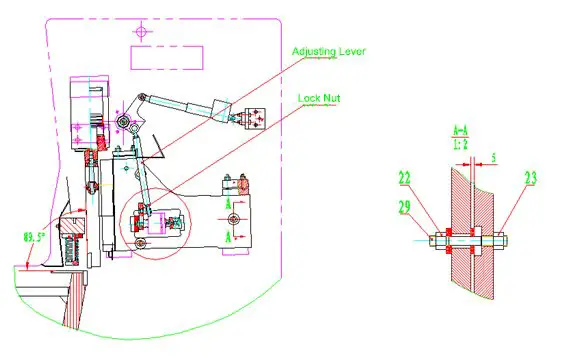
Blade Alignment: Before operation, align the cutting blade. The blade clearance should be set based on the thickness of the material being cut, typically 5-7% of the material’s thickness. Adjust the clearance by turning the flywheel with your hand to cause the upper and lower blade to reciprocate once, and then check the clearance with a feeler gauge.
Retaining Plate Adjustment: Based on the requirements of the material being cut, loosen the anchor bolt, adjust the position of the retaining plate, and tighten it. The shearing machine should be run 2-3 times before starting work to ensure good lubrication and error-free operation.
Operational Safety
Adjustment Precautions: Do not use percussion to loosen the backgauge device or adjust blade clearance. When adjusting the guide rail clearance and blade clearance, the machine must be stopped before making any adjustments. Do not reach into the cutting area or handle the material during operation.
Blade Maintenance: The blade must be sharp and should be sharpened or replaced promptly if damaged or worn.
Material-Specific Adjustments: When cutting different thicknesses and types of material, adjust the clamp spring pressure and blade clearance appropriately to prevent spring breakage or damage to the blade edge.
Prohibited Materials: Do not cut steel bars using the hydraulic shearing machine. Do not place any other items on the work table to avoid damage to the blade.
Operator Conduct
Continuous Supervision: The operator must not leave the machine during operation or allow anyone else to operate it.
Attention to Mechanisms: Pay close attention to the clamping mechanism, clutch, and brake for any signs of abnormal failure. Stay alert while shearing, and if you detect any abnormal behavior in the machine, stop shearing immediately, turn off the power, and inform maintenance personnel.
Post-Operation Procedures
Shutdown and Cleaning: Before leaving work, turn off the power, wipe down the equipment, and make a record of the inspection.
Material Restrictions
Prohibited Materials: Do not cut excessively long or thick plates, high-speed steel, tool steel, or cast iron. Do not cut explosive items, rods, excessively thin materials, or non-metal materials.
Additional Safety Measures
Clutch and Motor: The clutch should be off before starting, and the motor should not start with a load.
Empty Cutting Test: Before starting, test the empty cutting. Once everything is working well, then begin the cutting operation.
Pull Rod and Fastening: Check the pull rod for any signs of failure and make sure that the fastening screw is secure.
Finger Safety: Keep your fingers out of the blade’s path when feeding material. Do not cut material with two operators at the same time, and do not stand behind the shearing machine.
By adhering to these guidelines, operators can ensure the safe and efficient use of hydraulic shearing machines, minimizing the risk of accidents and equipment damage.
Matters to Consider During Hydraulic Shearing Machine Operation
Operating a hydraulic shearing machine requires careful attention to detail and adherence to safety protocols to ensure optimal performance and prevent accidents. Here are key considerations to keep in mind:
1. Blade Clearance Adjustment
Regularly check the blade clearance and adjust it according to the thickness of the different materials being cut. Proper blade clearance is crucial for achieving clean cuts and prolonging the lifespan of the blades.
2. Blade Sharpness and Cut Quality
Ensure that the blade is sharp and that the cut surface is free of scars, gas cuts, and protruding burrs. Dull blades can lead to poor cut quality and increased wear on the machine.
3. Safety During Adjustments
When making adjustments to the machine, it must be turned off to prevent personal injury and machine damage. Always follow the manufacturer’s guidelines for making adjustments safely.
4. Monitoring for Abnormalities
If abnormal noise or overheating of the oil tank is detected during operation, stop the shearing machine immediately to investigate the issue. The highest temperature of the oil tank should not exceed 60℃. Overheating can indicate potential issues with the hydraulic system that need to be addressed promptly.
5. Cutting Width Limitations
Do not attempt to cut strips, as this can damage the machine. The minimum width of the material being cut should not be less than 40mm. Cutting narrow strips can place undue stress on the blades and the machine’s frame.
6. Material Cutting Capacity
The cutting capacity of the hydraulic shearing machine depends on the strength of the material being cut. For example:
With a maximum cutting thickness of 16mm for Q235 steel (with a tensile strength of 450 MPa), the cutting thickness for Q345 steel would be 13mm.
For Q235 steel with a cutting thickness of 8mm, the cutting thickness for Q345 steel would be 6mm.
Understanding the material properties and adjusting the machine settings accordingly is essential for maintaining the machine’s integrity and ensuring precise cuts.
By following these guidelines, operators can ensure safe and efficient operation of hydraulic shearing machines, leading to high-quality output and extended machine life.
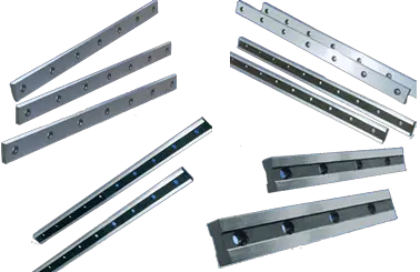
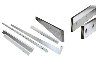
Blade of Hydraulic Shearing Machine
Shearing Machine Blade Material
The blades of hydraulic shearing machines are critical components that determine the quality and efficiency of the cutting process. These blades are typically made from high-quality tool steels, which are chosen for their hardness, toughness, and wear resistance. The most commonly used materials for shearing machine blades include:
High Carbon High Chromium Steel (D2): Known for its high wear resistance and toughness.
High-Speed Steel (HSS): Offers excellent hardness and heat resistance.
Alloy Tool Steel: Provides a good balance of hardness and toughness.
Tungsten Carbide: Extremely hard and wear-resistant, suitable for cutting very hard materials.
Chromium Vanadium Steel: Offers good toughness and wear resistance.
Manganese Steel: Known for its high impact strength and resistance to abrasion.
Carbon Tool Steel: Economical option with decent hardness and wear resistance.
Powder Metallurgy Steel: Provides uniform hardness and excellent wear resistance.
Standard Blade Hardness
The hardness of shearing machine blades is a crucial factor that affects their cutting performance and durability. The standard hardness for these blades varies depending on the thickness of the material they are designed to cut. Here are the typical hardness values for blades used in hydraulic shearing machines:
For 6.5/10mm thick materials: HRC 58/59
For 13/16mm thick materials: HRC 56/57
These hardness levels ensure that the blades can effectively cut through standard cold-rolled plates and most stainless steel plates.
Standard blade hardness table
6.5/10mm
HRC
58/59
13/16mm
HRC
56/57
Cutting Performance and Considerations
When cutting large quantities of stainless steel or other hard materials, rough edges may occur during the cutting process. This can be due to the increased wear and tear on the blades, which may not maintain their sharpness and precision over extended use. To address this issue, an optional blade with a slightly lower hardness (HRC 56/57) for 6.5/10mm shears is available. This blade is designed to provide a balance between hardness and toughness, reducing the occurrence of rough edges and improving the overall quality of the cut.
Additional Resources
For more detailed information on the materials used for hydraulic shear blades, you can refer to the guide on “8 Commonly Used Materials of Hydraulic Shears Blade.” This resource provides an in-depth look at the properties and applications of different blade materials, helping you choose the right blade for your specific cutting needs.By understanding the material composition and hardness of shearing machine blades, you can make informed decisions to optimize the performance and longevity of your hydraulic shearing machine.
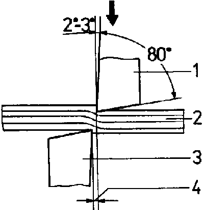
Shearing machine blade angle adjustment
Shearing Machine Blade Angle Adjustment
Importance of Blade Angle and Clearance
In the operation of shearing machines, the adjustment of the blade angle and clearance is crucial for achieving optimal cutting results. These adjustments are highly dependent on the material being processed, as different materials have varying properties such as thickness, hardness, and tensile strength.
Blade Angle Adjustment
The blade angle, often referred to as the “rake angle” or “tilt angle,” plays a significant role in the shearing process. Adjusting this angle can have various effects on the quality of the cut and the overall efficiency of the shearing machine.
Increasing the Blade Angle
Advantages: Increasing the blade angle can reduce the cutting force required, which can be beneficial when working with thicker or harder materials. This adjustment can also help in achieving a cleaner cut edge.
Disadvantages: However, a higher blade angle may lead to increased deformation, especially when cutting narrow strips. This deformation can manifest as warping or bending of the material, which is undesirable in precision applications.
Decreasing the Blade Angle
Advantages: Decreasing the blade angle can minimize deformation, resulting in a more accurate cut with less warping. This is particularly useful when precision is critical, such as in the fabrication of components that require tight tolerances.
Disadvantages: A lower blade angle may increase the likelihood of burrs forming on the cut edge. Burrs are small, rough projections left on the material, which can affect the finish quality and may require additional deburring processes.
Clearance Calculation
The clearance between the blades is another vital parameter that needs careful adjustment. Proper clearance ensures a clean cut and prolongs the life of the blades.
Standard Material Consideration: The clearance should be adjusted based on the thickness and type of material being sheared. For instance, softer materials like aluminum may require a different clearance compared to harder materials like steel.
Impact on Shearing Quality: Incorrect clearance can lead to poor shearing quality, such as ragged edges or excessive wear on the blades. Properly calculated clearance helps in achieving a smooth cut and reduces the need for frequent blade maintenance.
Practical Adjustment and Monitoring
Modern shearing machines often come equipped with advanced control systems that allow for real-time adjustments and monitoring of blade angle and clearance.
Gas Cabinet Diagram: Some shearing machines feature a gas cabinet with a diagram that can be adjusted at any time to optimize shearing results. This diagram provides a visual representation of the current settings and allows operators to make precise adjustments based on the material and desired outcome.
External System Analysis: While external system analysis is not required in this context, it is essential to regularly monitor and adjust the shearing parameters to maintain optimal performance and extend the lifespan of the machine.
The adjustment of blade angle and clearance in shearing machines is a critical aspect of achieving high-quality cuts and efficient operation. By understanding the effects of these adjustments and making precise changes based on the material properties, operators can enhance the performance of their shearing machines and produce superior results. Regular monitoring and adjustments, facilitated by advanced control systems, further ensure consistent and reliable shearing operations.
Minimum Cutting Width of Hydraulic Shearing Machine
When using a hydraulic shearing machine, the minimum cutting width is a critical factor to consider to ensure the quality and precision of the cut. The guidelines for minimum cutting width vary depending on whether the shearing is precise or not.
Non-Precise Shearing
For non-precise shearing, the width of the sheared strip should not be less than three times the thickness of the plate. This guideline helps to prevent excessive deformation and ensures a more stable cutting process. For example, if the plate thickness is 5 mm, the minimum width of the sheared strip should be at least 15 mm.
Precision Shearing
For precision shearing, the requirements are more stringent. The width of the sheared material should be at least six times the thickness of the plate. This higher ratio is necessary to avoid distortion or bending of the material, which can compromise the precision and quality of the cut. For instance, if the plate thickness is 5 mm, the minimum width of the sheared strip should be at least 30 mm.
Shearing Accuracy of Hydraulic Cutting Machine
When evaluating the quality of shearing performed by a hydraulic cutting machine, several key parameters need to be considered, especially for a 2mm ordinary cold-rolled plate. These parameters ensure the precision and consistency of the shearing process, which is critical for maintaining the quality of the final product. Below are the detailed criteria for assessing shearing accuracy:
Key Parameters
Parallelism Tolerance:
Setting: X = 100mm
Requirement: The parallelism tolerance of the sample should not exceed 0.15mm over any 1000mm length.
Explanation: This means that when a 100mm segment is measured along a 1000mm length, the deviation in parallelism should be within 0.15mm. This ensures that the cut edges remain parallel to each other, which is crucial for the fit and finish of the sheared parts.
Straightness:
Setting: X = 100mm
Requirement: The straightness of the sample should not exceed 0.25mm over any 1000mm length.
Explanation: This criterion ensures that the cut edge does not deviate more than 0.25mm from a straight line over a 1000mm length. Maintaining straightness is important for the structural integrity and assembly of the sheared components.
Repeat Positioning Accuracy of the X-axis:
Requirement: The repeat positioning accuracy should be 0.02mm.
Explanation: This parameter indicates the machine’s ability to return to a previously set position with a high degree of accuracy. A repeat positioning accuracy of 0.02mm ensures that each cut is made precisely at the intended location, which is essential for batch production and maintaining uniformity across multiple pieces.
Additional Considerations
Sample Length: The length of the sample can be equal to the width of the plate being sheared. This flexibility allows for various sample sizes to be tested, ensuring that the shearing machine performs consistently across different dimensions.
Tensile Strength of the Sample:
Requirement: The tensile strength of the sample should not exceed σb ≤ 450 MPa.
Explanation: The tensile strength limit ensures that the material being sheared is within the machine’s capacity. Exceeding this limit could result in inaccurate cuts or damage to the machine.
By adhering to these parameters, the shearing accuracy of a hydraulic cutting machine can be effectively evaluated and maintained. Ensuring parallelism, straightness, and repeat positioning accuracy within the specified tolerances guarantees high-quality shearing results, which are essential for the subsequent manufacturing processes and the overall quality of the final product.
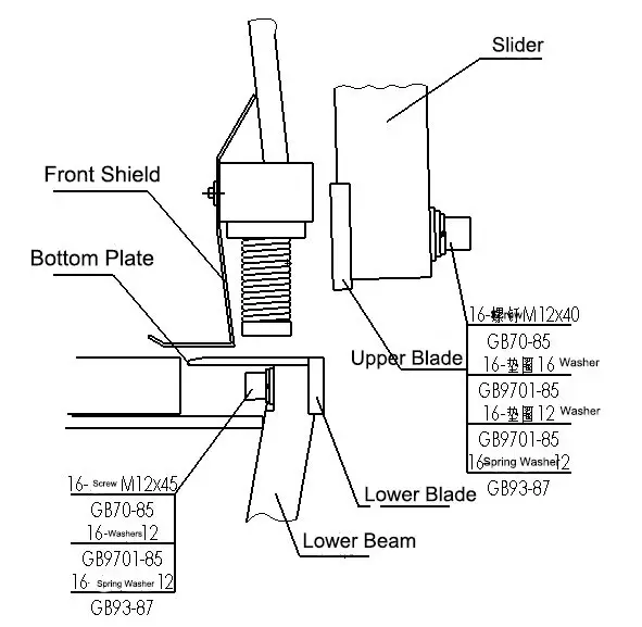
Installing the Upper and Lower Blades
Upper Blade Installation
Mount the Blade:
Securely fasten the M12*40 screws to the blade. Do not tighten the screws at the two ends yet.
Initial Positioning:
Use a stick to hold the blade in place. Gradually tighten the installed M12*40 screws one by one until the surface of the blade is fully in contact with the slider.
Final Tightening:
Lower the slider and turn off the pump motor. Then, tighten the M12*40 screws at both ends of the blade.
Torque Specification:
Ensure that the tightening torque for the blade screws is 35 N·m.
Lower Blade Installation
Prepare the Machine:
Start the oil pump and raise the slider to its highest point. Once the oil pump is turned off, place the blade in position.
Initial Positioning:
Loosen the M12*45 hexagon screws slightly (do not tighten too much for now). Use a stick to press the blade so that it is close to the bottom of the worktable.
Final Tightening:
Tighten the M12*45 screws in turn as required.
Important Note
The blade screws should be tightened to the specified torque to ensure the proper functioning of the machine.
Additional Tips
Safety First: Always ensure the machine is turned off and properly secured before beginning any maintenance or installation work.
Check Alignment: After installation, double-check the alignment of the blades to ensure they are parallel and correctly positioned.
Regular Maintenance: Regularly inspect the blades and screws for wear and tear, and ensure they are always tightened to the specified torque.
By following these detailed instructions, you can ensure the proper installation and optimal performance of the blades on your hydraulic shearing machine.
Adjustment of Blade Clearance in Shearing Machines
Blade clearance is a critical factor in the operation of shearing machines, directly impacting the quality of the sheared surface and the lifespan of the blade. Proper adjustment ensures efficient and safe operation. Here’s a detailed guide on adjusting blade clearance:
1. Blade Clearance That Is Too Small
Typically, the standard clearance between the upper and lower blades is around 0.02mm, which is roughly the thickness of a standard A4 paper. A common method for adjusting blade clearance during installation is to use the shearing machine to cut paper.
Consequences of Too Small Blade Clearance:
Excessive Pressure on Cutting Edge: When the clearance is too small, the cutting edge of the blade is under excessive pressure, which can directly damage and dull it.
Blade Dislocation: Dislocation between the upper and lower blades can occur, causing the upper blade to cut into the lower blade. This can lead to the cutting edge cracking, posing a risk to the operator.
2. Blade Clearance That Is Too Large
This is a common mistake made by non-professionals during blade installation. To prevent the blades from striking each other, they often increase the gap unnecessarily, which is incorrect.
Consequences of Too Large Blade Clearance:
Reduced Cutting Accuracy: When the blade clearance is too large, the accuracy of the cut plate is affected, leading to many metal burrs on the cutting edge, especially when cutting thin sheet metal materials.
Trapped Sheet Metal: The sheet metal may get trapped between the upper and lower blades, making it difficult to remove. This not only wears out the blades but may also cause the shearing machine to shut down. However, this issue may not be as noticeable when cutting thick plates.
Regular Adjustment of Blade Clearance
Regular adjustment of the blade clearance is necessary after prolonged use of the shears. It is recommended to set the blade clearance at around 10% of the metal sheet thickness. The lower blade is fixed on the hydraulic shearing machine, and the blade clearance can only be adjusted by changing the position of the upper blade. The minimum clearance should be between 0.05-0.1mm.
Steps for Adjustment:
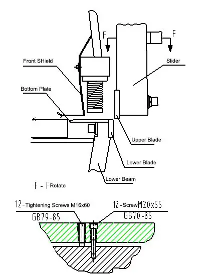
Adjusting the Ends: The blade clearance at the ends can be adjusted by adjusting the pole (as shown in the figure).
Hex Screw Adjustment: If the clearance between the lower blade does not meet the requirements, it can be adjusted by referring to the figure and adjusting the M1660 and M1265 hex screws to ensure that the parallelism allowance of the upper and lower blades is within 0.05mm.
Repeat Adjustments: Repeat adjustments of the M1265 and M1660 inner hex screws may be necessary to achieve the ideal blade clearance.
Proper blade clearance adjustment is vital for maintaining the quality of the sheared surface and extending the lifespan of the blades. Regular checks and adjustments, especially after prolonged use, ensure the shearing machine operates efficiently and safely.
Maintenance of Hydraulic Shearing Machine
Proper maintenance of a hydraulic shearing machine is crucial for ensuring its longevity, reliability, and safety. This guide outlines the essential maintenance tasks, including daily lubrication, cleaning, and specific safety instructions.
1. Safety Instructions
When conducting any maintenance on the shearing machine, it is imperative to prioritize safety. Follow these steps to ensure a safe working environment:
Power Supply: Always shut off the power supply before starting any maintenance work.
Discharge Time: Wait for at least 20 seconds to allow the capacitor and servo amplifier to discharge completely.
Hydraulic Parts Operation: Be cautious as the slider may move during the operation of hydraulic parts. Adhere to these guidelines:
Do not place arms or feet between the upper and lower blades.
Before removing the valve:
Shut off the pump.
Lower the slider to the oil cylinder without oil. If this is not possible, use a wooden block to cushion it and monitor any pressure changes in the system due to the removal of the slider valve.
Ensure no operation is performed on the shearing machine without proper safety measures in place.
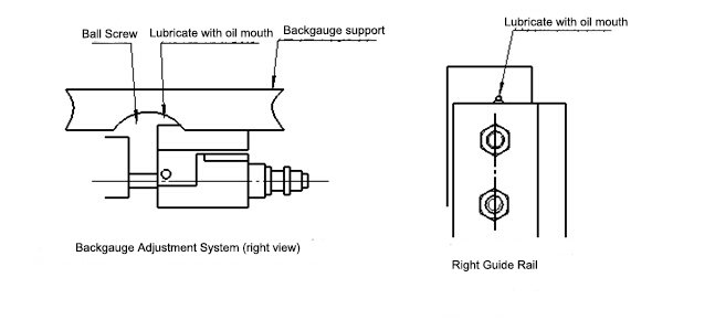
2. Shearing Machine Lubrication
Lubrication is essential for the smooth operation of the shearing machine. Follow these guidelines:
Frequency: Lubricate the machine once a week or every 40 hours of operation.
Lubricant: Use calcium-based grease.
Application: Inject the grease into each lubrication point using a grease gun.
The lubrication points are shown below:
No.
Lubrication point
Grease
1
Ball screw, nut and screw end bearing
Calcium base grease
2
Guide rail and slide guide base
Calcium base grease
3
Sliding block guide rail
Calcium base grease
4
Guide rail and clearance adjustment screw and nut
Calcium base grease
3. Hydraulic Oil and Calcium Base Grease
For optimal performance, use the following hydraulic oils:
Manufacturer
Hydraulic Oil
ESSO
NUTO H46
SHELL
TELLUS 46
GULF
HARMONY 46 AW
BP
HLP46
TBXACO
RANDO OIL 46
MOBIL OIL
MOBIL DTE 25
4. Change Hydraulic Oil
Regular replacement of hydraulic oil is crucial for maintaining the shearing machine’s performance. Follow these steps:
Initial Replacement: Replace the hydraulic oil after the first 2000 hours of operation.
Subsequent Replacements: Replace the oil every two years or after 4000 hours of use.
Preparation: Clean the area around the tank cover and tubing to prevent contamination.
Draining: Drain the hydraulic oil when it is warm, and ensure the slider is at the upper dead point.
Cleaning: Clean the inside of the tank using a clean cloth and a suitable solvent.
Filter Replacement: Replace the oil filters.
Refilling: Add new hydraulic oil.
Circulation: Run the oil pump for about an hour to circulate the new hydraulic oil before restarting the shearing machine.
To ensure reliable operation, adhere to the following maintenance procedures, which are based on a 5-day workweek with 8 hours of work per day:
Daily Tasks: Perform daily lubrication and cleaning.
Weekly Tasks: Conduct a thorough lubrication of all specified points.
Periodic Tasks: Replace hydraulic oil and filters as per the recommended schedule.
By following these maintenance guidelines, you can ensure the efficient and safe operation of your hydraulic shearing machine, ultimately extending its service life and maintaining its performance.
Item
The attention points
Period
Whole body
Brush the dust and dirt on the machine, gently oil the blade
weekly
Slider
Gun lubrication
weekly
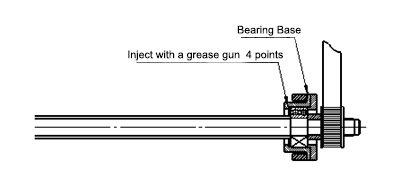
Backgauge support bearing
Gun lubrication
weekly
Backgauge ball screw
Gun lubrication
weekly
Slider guide rail
Check the derrick adjustment
3 month
Check backgauge positioning
If the position error of the backstop blocks exceeds + 0.1mm, please reset
3 month
Hydraulic parts and systems
Check the tank oil level. If you need to replace the new oil, change the filter to 20um
weekly
Drain the old oil and add the new oil
12 months for the 1st time
Check all valves, hydraulic system, tubing and connectors to prevent leakage, blockage and replacement when necessary.
3 month
Check the cleanness of the import and export filters
3 month
Footswitch
Check foot switch pedal, in case of deformation, breakage, etc
monthly
Electrical control equipment
Check the limit switches in the electric cabinet, and the wear and burn must be replaced in time
3 month
Shears
Observe wear and abnormality of air metal shears
3 month
Finger protector
Check the sheet shears protection device to prevent the finger from entering the dangerous area
monthly
Hydraulic Shearing Machine Troubleshooting
Hydraulic Shearing Machine Instruction Manual
You can click the below link to view both the instruction manual for swing beam shears as well as guillotine shears.
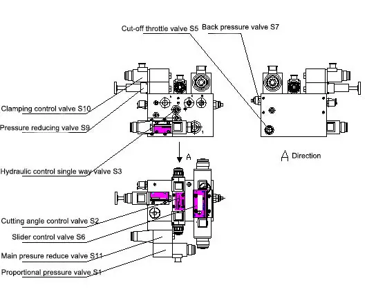
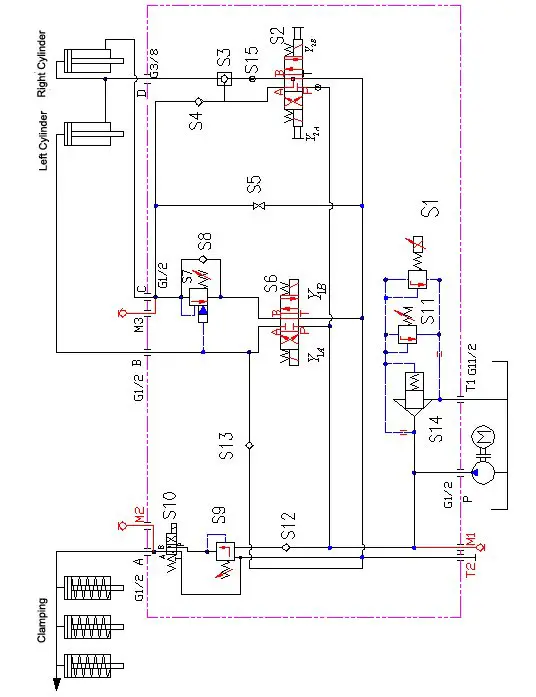
When the oil from the main oil line is directed into the three-position four-way directional control valve S6, S6Y1A gets energized. The oil then enters S6B through S6P, opens the one-way valve S8, and flows into the lower chamber of the right cylinder (the left and right cylinders are connected in series), causing the oil to flow from the right tank into the lower chamber of the left cylinder.
The oil in the upper chamber of the left cylinder enters S6A and then S6T, causing the slider to move up.
If S6Y1 is energized, the oil will enter S6A through S6, then into the upper chamber of the left cylinder, and then into the upper chamber of the right cylinder.
The oil will overcome the pressure of the back pressure valve S7 and enter S6T through S6B, then return to the oil tank, causing the slider to move down.
2. Adjusting the Shear Angle
If there is no set value for the shear angle of the shearing machine, the slider block cannot move up and down. Therefore, the shear angle must be set through the controller.
The shear angle adjustment is as follows:
When the oil is directed into the three-position four-way directional control valve S2, and Y2A is energized, the oil will enter S2B through S2P, open the hydraulic control single-way valve S3, and flow into the lower chamber of the left cylinder and the upper chamber of the right cylinder, causing the upper chamber of the left oil cylinder to not form a circuit and not move.
When the oil in the lower chamber of the right cylinder returns to the oil tank through S6T, the back pressure valve S7, and the S6B valve, the cutting angle becomes smaller.
Conversely, if Y2B is energized, the oil will enter S2A through S2P, open the single-way valve S4, and flow into the lower chamber of the right oil cylinder.
The oil in the upper chamber of the right cylinder can only enter the hydraulic control single-way valve S3 (at this point, the S3 valve is open), and the oil will enter S2T through S2B, causing the shearing angle to become larger.
The relationship between shear angle and shear force:
Mild Steel (mm)
6
8
10
13
13
13
13
16
16
20
Stainless Steel (mm)
3
4
6
8
8
8
8
10
10
12
Shear Force (KN)
132
220
430
730
620
620
650
730
850
1270
Shear Angle Adjustment (°)
0.5-2.5
0.5-2.5
0.5-2
0.5-2
0.5-2.5
0.5-2.5
0.5-2
0.5-3
0.5-2.5
0.5-3
3. The work of the hold-down cylinder
When the oil enters the directional control valve S9 through the clamping proportional control valve S10 (the proportional pressure of which is controlled by an electrical arc pressure adjustment switch), upon activation of S9, the oil will enter S9A through S9P and then enter the upper chamber of the clamping device, causing the clamping piston to move downward and create compression.
When S9 loses electricity, the clamping piston will be pushed upward by the internal spring of the clamp, forcing the oil in the upper chamber of the clamping cylinder to enter S9T through the S9 valve, resetting the clamping device.
** Hydraulic shearing machine structure drawing
List of Vulnerable Parts of The Hydraulic Shearing Machine
Under the guidance of the sheet metal workshop director, the hydraulic shearing machine operator must:
Adhere to the company’s regulations.
Follow the leadership’s directives.
Maintain staff unity.
Put forth positive effort.
Act in an economical manner.
Perform quality work.
Produce qualified products.
Maintenance and Record Keeping
Responsible for daily routine maintenance, including checking, repairing, adjusting, and tightening the shears.
Keep detailed records of maintenance activities.
Safety and Operation Procedures
Familiarize with and strictly follow the safety technical operation procedures.
Master the normal operation methods of the shearing machine.
Accurately judge abnormal situations and take timely and correct emergency measures.
Operate the machine strictly according to the operating rules; the equipment can only be started when the working environment is normal.
Pre-Operation Checks
Check the oil storage tank for sufficiency.
Inspect valves and pipelines after starting the oil pump to ensure pressure meets requirements.
Observe the resistance of blade movement and start cutting only when the test is normal (sudden starts are prohibited).
Material Handling and Cutting
Do not cut laminated sheet material, trim plate edges with burrs, or shear narrow plates and short materials that can’t be tightly pressed.
Adjust blade clearance according to plate thickness (not to exceed 1/30 of the plate thickness).
Ensure the blade is fastened firmly and kept parallel to prevent accidents.
Keep the blade edge sharp and repair or replace it if dull or cracked.
Press materials firmly onto the plate while shearing and avoid shearing under pressure.
Operational Restrictions
Do not adjust the hydraulic valve yourself.
Do not use the shearing machine for materials exceeding its capacity, such as super length/thickness, steel, high carbon steel, alloy tool steel, cast iron, or brittle materials.
Frequently check fastening screws for looseness.
Do not operate the shearing machine alone; coordinate with another person for material delivery, dimension accuracy, and material handling.
Adjust blade clearance according to plate thickness and avoid cutting two different specifications or materials simultaneously.
Keep the operator’s fingers at least 200mm away from the scissor shears and the compression device.
Determine cutting thickness according to the plate limit strength/thickness curve diagram.
Do not place other items on the workbench.
Post-Operation Procedures
Clean the machine after stopping.
Run the shearing machine in empty mode after adjusting the blade for alignment tests.
Pile up finished products, clear the field, cut off power, and lock the switch box before leaving the work area.
By adhering to these responsibilities and procedures, the hydraulic shearing machine operator ensures safe, efficient, and high-quality operations within the sheet metal workshop.
Price of Hydraulic Shearing Machine
Hydraulic shearing machines are essential tools in the metal fabrication industry, primarily used to cut steel plates. These machines come in various configurations, with the most common being designed to handle steel plates with a thickness of 4-8mm and a width of 2.5-3.2m.
Typical Prices
Hydraulic Swing Beam Shear:
4 * 2500 Hydraulic Swing Beam Shear: This model, which can cut steel plates up to 4mm thick and 2.5m wide, is typically priced around 6000 USD.
6 * 3200 Hydraulic Swing Beam Shear: This model, capable of cutting steel plates up to 6mm thick and 3.2m wide, generally costs approximately 10000 USD.
Hydraulic Guillotine Shear:
The price of a hydraulic guillotine shear is generally about 2000 USD more than that of a comparable swing beam shear. This means that if a swing beam shear is priced at 6000 USD, a similar capacity guillotine shear would be around 8000 USD. Similarly, if a swing beam shear is priced at 10000 USD, the guillotine shear would be approximately 12000 USD.
Differences Between Swing Beam Shear and Guillotine Shear
Swing Beam Shear: In this type of shear, the upper blade swings in an arc to cut the material. It is typically more economical and simpler in design, making it suitable for less demanding applications.
Guillotine Shear: This type of shear has a straight up-and-down cutting action, providing higher precision and better cutting quality. It is generally more robust and suitable for thicker or harder materials, which justifies the higher price.
Understanding the differences and price points of these machines can help in making an informed decision based on the specific requirements of the cutting tasks at hand.
The detailed difference between swing beam shear and guillotine shear can be checked here.
How To Choose The Right Hydraulic Shearing Machine
Selecting the appropriate hydraulic shearing machine for your needs involves several critical steps. This guide will help you navigate the process to ensure you make an informed decision that aligns with your specific requirements and budget.
Determining Specifications and Cost Range
Identify Your Needs: Start by understanding the specific needs of your operation. Consider the type of materials you will be cutting, the thickness of these materials, and the volume of work. This will help you determine the necessary specifications for the hydraulic shearing machine, such as cutting capacity, blade length, and cutting angle.
Set a Budget: Establish a cost range that aligns with your financial constraints while ensuring you do not compromise on essential features. Remember that the initial cost is not the only expense; consider maintenance, operation, and potential downtime costs.
Finding a Manufacturer
Research Manufacturers: Look for reputable manufacturers who specialize in hydraulic shearing machines. Utilize resources such as industry directories, trade shows, and online platforms to compile a list of potential suppliers. Pay special attention to manufacturers with a strong presence in the market, such as those in China, which is known for its extensive manufacturing capabilities.
Verify Capabilities: Ensure the manufacturers on your list have the capability to produce the specific type of hydraulic shearing machine you need. This step is crucial to avoid wasting time on suppliers who cannot meet your requirements.
Checking the Models
Compare Models: Different manufacturers offer various models with distinct features and capabilities. Compare these models based on your identified needs. Look for details such as cutting precision, ease of operation, safety features, and energy efficiency.
Check Availability: Confirm that the model you are interested in is available. Some manufacturers may source certain models from other companies, so it is important to verify the origin and availability of the machine.
Examining the Company and Machine
Visit the Manufacturer: If possible, visit the manufacturer’s facility to see the machines in operation. This will give you a better understanding of the machine’s build quality and performance.
Gather Information: Collect detailed information about the machine, including technical specifications, warranty, and after-sales service. A manufacturer with robust after-sales support can significantly reduce downtime and maintenance costs.
Evaluate Service: Consider the manufacturer’s reputation for customer service. Read reviews, ask for references, and speak to other customers if possible. Excellent service can be as important as the machine itself.
Signing a Contract and Making a Deposit
Review the Contract: Carefully review the contract terms before signing. Ensure all agreed-upon specifications, delivery timelines, and payment terms are clearly stated. Look for any clauses that might be unfavorable or in breach of local laws.
Make a Deposit: Once you are satisfied with the contract, proceed with making the deposit. This step typically secures your order and initiates the manufacturing process.
Conclusion
Choosing the right hydraulic shearing machine involves careful consideration of your specific needs, thorough research of manufacturers, and diligent evaluation of available models and services. By following these steps, you can make an informed decision that will enhance your operational efficiency and productivity.
As the founder of MachineMFG, I have dedicated over a decade of my career to the metalworking industry. My extensive experience has allowed me to become an expert in the fields of sheet metal fabrication, machining, mechanical engineering, and machine tools for metals. I am constantly thinking, reading, and writing about these subjects, constantly striving to stay at the forefront of my field. Let my knowledge and expertise be an asset to your business.
Have you ever wondered which companies are leading the hydraulic shearing machine industry? This article explores the top 26 manufacturers worldwide, detailing their history, specialties, and global reach. From long-established…
Ever wondered how powerful machines transform raw metal into precise, usable parts? This article unveils the secrets of the hydraulic shearing machine, a marvel of engineering. Learn how it cuts…
Ever wondered why some metal sheets come out perfectly flat while others warp and distort? This article reveals the secrets behind cutting forces in rotary plate shears. You'll learn how…
Have you ever wondered how massive sheets of metal are precisely cut with minimal effort? In this article, we explore the fascinating world of hydraulic guillotine shears. You'll learn about…
Ever wondered what makes the perfect shear blade? In this article, we'll explore the fascinating world of die steels, from cold-work to hot-work varieties. You'll uncover the secrets behind their…
Ever wondered how to maximize the efficiency and safety of your shearing machine? This guide delves into essential tips for operating and maintaining these powerful tools. From choosing the right…
Ever wondered who the top players are in the shearing machine industry? In this article, we'll explore the leading shearing machine manufacturers in China for 2023. You'll discover companies that…
What sets hydraulic guillotine shears apart from swing beam shears, and why do these distinctions matter for your metalworking projects? This article explores the key differences, including blade movement, shear…
What causes the hydraulic system in a guillotine shear to fail? This article explores the common issues such as pressure loss, valve malfunctions, and automatic falling of the presser foot.…


