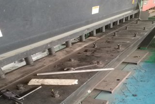
1. Remove the front workbench plate, front support arm and shroud
As shown below:
2. Blade removal
(1) When disassembling, first remove the blade, leaving one bolt in the center of the blade to loosen it. Do not remove this bolt to prevent the blade from falling and causing injury to people.
After removing all other bolts, two people should work together to remove the lower blade. The blade has two bolts that can be used by two people to lift it.
② Before proceeding, set the operation panel to “Manual Shift Mode,” which can only be performed when the machine is in stop mode. This is shown in the accompanying figure.
- The backgauge distance should be set to over 900.
- To adjust the shear angle of the upper blade, change it to 0.5°. Note that a larger angle will result in a greater tilt of the upper blade.
- To prevent the upper and lower blades from colliding, change the upper and lower blade clearance to 0.5 or more. This will ensure that the loading of both blades does not cause them to bump into each other.
3. Removal of the upper blade
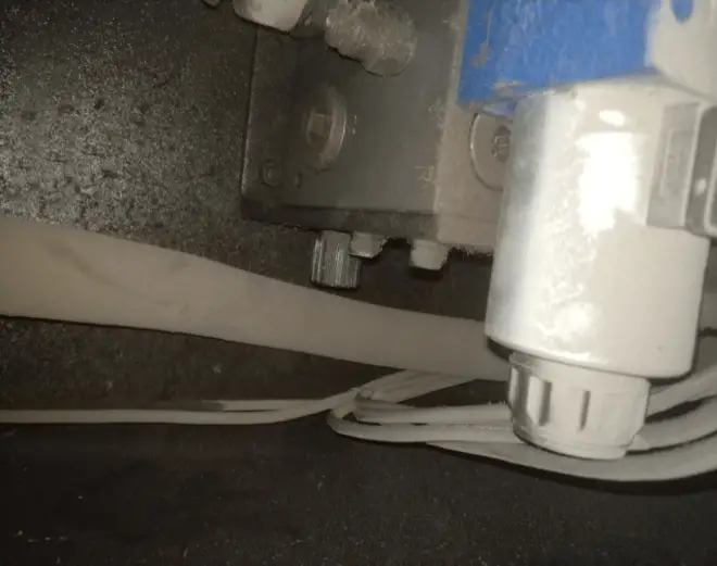
When removing the unit, first loosen the middle bolt but do not remove it. Then, loosen the pressure reducing valve inside the unit by turning it counterclockwise, as shown below.
The greater the counterclockwise turn of the pressure reducing valve, the faster the upper blade will drop.
Once the upper blade has been lowered enough to reveal the two hidden bolts, close the pressure reducing valve by turning it clockwise all the way. Then, you can remove the two hidden bolts in the upper blade.
After removing these bolts, activate the unit’s oil pump, and the upper blade will return to its starting position, making it easier to remove. To remove the upper blade, it can be tilted at a larger angle.
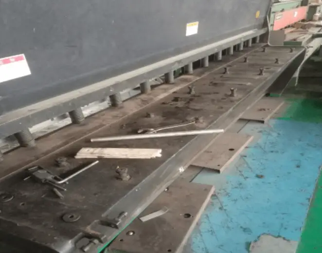
When disassembling the unit, it is important to have multiple people working together to prevent injury. Use a wooden board in the center to provide additional support and stability.
4. Clean up oil, dust and dirt from upper and lower blades
Before installation, inspect the tool for any damage and mark the available surface. Prepare the surface for installation by cleaning it and making any necessary repairs or adjustments.
5. Blade installation
The installation process is the reverse of the removal process.
Install the blade first, using two bolts to secure it slightly to make it easier for two people to carry it. Then, attach the bolt to the device and install the lower blade by screwing it into place. The hidden bolts on both sides of the upper blade do not need to be installed first.
Finally, in the operation panel, adjust the settings to “Manual Shift Mode” with the following values:
Backgauge distance: over 900, Shear angle: 1.7° (greater than 1.5°), and Clearance: 0.5 or more. These settings are designed to prevent the upper and lower blades from bumping into each other during installation.
6. Upper and lower blade fixation
When installing the blade, one person must always be in control of the pressure reducing valve.
Lower the upper blade slowly, and close the pressure reducing valve when the upper and lower blades overlap. Use a feeler gauge to check the clearance between the blades, it should be 0.5mm. If the gap is too small (e.g. 0.1 or 0.2), adjust it again in the “Manual Shift Mode.”
If the clearance is appropriate and the blades are not touching, continue to release the pressure reducing valve. Close the pressure reducing valve again (clockwise) when the upper blade touches the lower blade on the far right side. Use the feeler gauge to check the clearance again to ensure that the blades are not touching.
Activate the oil pump to bring the upper blade ram to the starting position. Use a wooden plank to hold the blade in place and slowly release the pressure reducing valve.
Tighten the nearby bolts one by one, from left to right, using the same method. After all the bolts have been tightened, drop the upper blade and tighten the last two hidden bolts (which are shorter in length).
7. Gap correction
Use a plug gauge to check the clearance on both the upper and lower blades and verify that it matches the machine’s readings. If there are discrepancies, follow these steps to make adjustments:
(1) Two people are required to adjust the clearance using a live wrench. One person should hold the hexagonal bar in place while the other person loosens the nuts at both ends of the bar, as illustrated in the accompanying picture.
Send the nuts at each end to the top, then use a wrench to turn the hex bar (adjusting lever). Rotate the screw clockwise to reduce the clearance and counterclockwise to increase it (depending on the site).
(2) Use this method to adjust the gap on both sides, ensuring that the clearance matches the machine display. The upper and lower tool sides must be matched before tightening the nuts on both ends of the screw.
8. Once the gap has been adjusted, it is necessary to verify the correct distance of the backgauge
If an error requires adjustment, adjust as follows.
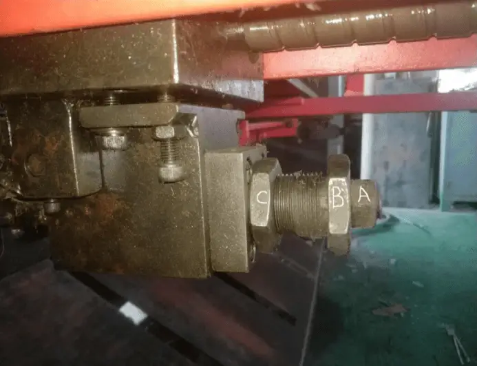
① To adjust the backstop, move it to the back position where the machine displays 900mm. Loosen nut “A” and then nut “C”. Use a wrench to turn the “B” adjusting screw. Each turn of the screw is approximately 2.3mm and rotating it clockwise reduces the size, while rotating it counterclockwise increases it.
② Once the backstop adjustment is done, tighten nut “A” first and then nut “C”. Check the accuracy of the adjustment by using the shearing plate until the test piece passes.