In fluid pipeline systems, regulating valves are control units, and their investment accounts for 30% to 50% of the pipeline engineering cost.
The main functions of valves are to open and close, to throttle, to regulate flow, to isolate equipment and pipeline systems, to prevent medium backflow, and to regulate and exhaust pressure.
Valves are also the most complex components in pipelines, generally assembled from multiple parts with high technical content.
With the rapid development of the petrochemical industry, media in petrochemical production equipment are mostly toxic, flammable, explosive, and highly corrosive, and operating conditions are complex and harsh, with high operating temperatures and pressures, and long start-up cycles.
Once a valve fails, it can cause medium leakage, polluting the environment and causing economic losses, and in severe cases, it can cause the equipment to shut down production, or even cause a catastrophic accident.
Therefore, in pipeline design, choosing valves scientifically and reasonably can not only reduce the construction cost of the equipment but also guarantee safe operation.
This article mainly introduces the selection methods of various commonly used valves, such as gate valves, globe valves, throttle valves, plug valves, ball valves, and diaphragm control valves.
1. Key points for valve selection
1. Clearly define the purpose of the valve in the equipment or device.
Determine the working conditions of the valve, such as the properties of the applicable medium, working pressure, working temperature, and operation control method.
2. Properly select the type of valve.
The correct selection of the valve type is a prerequisite for the designer’s full grasp of the entire production process and operating conditions.
When selecting the valve type, the designer should first grasp the structural characteristics and performance of each type of valve.
3. Determine the end connection of the valve.
In threaded connections, flange connections, and welding end connections, the first two are more commonly used. Threaded connections are mainly used for valves with nominal diameters below 50mm.
If the diameter size is too large, the installation and sealing of the connection part are very difficult. Flange-connected valves are relatively convenient to install and disassemble, but they are heavier and more expensive than threaded-connected valves.
Therefore, they are suitable for connecting pipelines of various diameters and pressures.
Welding connections are more reliable than flange connections under heavier loads, but they are more difficult to dismantle and install.
Therefore, their use is limited to occasions where they can operate reliably for a long time, or where operating conditions are heavy and temperatures are high.
4. Selection of valve materials.
When selecting the materials for the valve body, internal parts, and sealing surface, besides considering the physical properties (temperature, pressure) and chemical properties (corrosion) of the working medium, the cleanliness of the medium (presence of solid particles) should also be taken into account.
In addition, relevant regulations of the country and user department should be referred to.
Choosing the correct and reasonable material for the valve can achieve the most economical service life and best performance.
The valve body material is selected in the order of cast iron-carbon steel-stainless steel, and the seal ring material is selected in the order of rubber-copper-alloy steel-F4.
5. Others
In addition, the flow rate and pressure level of fluid flowing through the valve should be determined, and appropriate valves should be selected using available data such as valve product catalogs and samples.
2. Introduction to commonly used valves.
There are many types and complex varieties of valves, including gate valves, globe valves, throttle valves, butterfly valves, plug valves, ball valves, electric valves, diaphragm valves, check valves, safety valves, pressure reducing valves, steam trap valves, and emergency cutoff valves. The commonly used valves are gate valves, globe valves, throttle valves, plug valves, butterfly valves, ball valves, check valves, and diaphragm valves.
1. Gate valve
A gate valve is a valve that can open or close a fluid passage by driving the closing member (valve plate) up and down along the sealing surface of the valve seat with a valve stem.
Gate valves have better sealing performance and lower fluid resistance than globe valves. They are easier to open and close, and have certain regulating performance.
They are one of the most commonly used shut-off valves.
The disadvantages of gate valves are the large size, complex structure compared to globe valves, and the sealing surface is prone to wear and difficult to repair, so they are generally not suitable for throttling.
According to the position of the thread on the valve stem, gate valves can be divided into two types: rising stem and non-rising stem.
According to the structural characteristics of the gate plate, they can be divided into wedge-type and parallel-type.
2. Globe valve
A globe valve is a downward-closing valve. The closing member (valve disc) is driven by a valve stem to move up and down along the axis of the valve seat (sealing surface).
Compared with gate valves, globe valves have better regulating performance, poorer sealing performance, simple structure, easy manufacturing and maintenance, higher fluid resistance, and cheaper price.
They are a commonly used shut-off valve and are generally used in medium-sized and small-diameter pipelines.
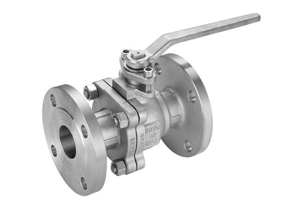
3. Ball valve
The closing member of a ball valve is a ball with a circular through-hole, which rotates with the valve stem to achieve opening and closing of the valve.
Ball valves have a simple structure, quick opening and closing, convenient operation, small size, light weight, fewer components, low fluid resistance, good sealing performance, and easy maintenance.
4. Throttle valve
The structure of a throttle valve is basically the same as that of a globe valve except for the throttle disc, which has different shapes and characteristics and has a smaller diameter than the valve seat.
It is not suitable to have too large of a diameter, as the increased medium flow rate from the smaller opening height could accelerate erosion against the throttle disc.
Throttle valves have small dimensions, light weight, good regulating performance, but low regulating accuracy.
5. Plug valve
A plug valve has a plug with a through-hole as the closing member. The plug rotates with the valve stem to achieve opening and closing of the valve.
Plug valves have a simple structure, quick opening and closing, easy operation, low fluid resistance, fewer components, and light weight. Plug valves can be straight-through, three-way, or four-way.
Straight-through plug valves are used to cut off the medium, and three-way and four-way plug valves are used to change the direction of the medium or to distribute the medium.
6. Butterfly valve
A butterfly valve uses a butterfly plate to rotate 90 degrees inside the valve body to complete the opening and closing action. Butterfly valves have small size, light weight, simple structure, and only a few components.
They can be quickly opened and closed by rotating 90 degrees, and are easy to operate.
When the butterfly plate is fully open, the thickness of the plate is the only resistance that the medium flows through the valve body, so the pressure drop generated by the valve is small, and the valve has excellent flow control characteristics.
Butterfly valves come in two sealing types: elastic soft sealing and metal hard sealing.
For elastic sealing valves, the sealing ring can be embedded in the valve body or attached to the circumference of the butterfly plate, which has good sealing performance and can be used for throttling, as well as for medium-vacuum pipelines and corrosive media.
Metal-sealed valves generally have longer service life than elastic-sealed valves, but it is difficult to achieve complete sealing. They are usually used in situations where the flow and pressure drop vary greatly and require good throttling performance.
Metal sealing can adapt to higher operating temperatures, while elastic sealing has the defect of being limited by temperature.
7. Check valve
A check valve is a valve that can automatically prevent fluid from flowing back. The closing member of a check valve opens under the action of fluid pressure, allowing fluid to flow from the inlet side to the outlet side.
When the pressure on the inlet side is lower than that on the outlet side, the closing member automatically closes under the action of factors such as fluid pressure difference and its own weight, to prevent fluid backflow.
Check valves can be divided into lift-type check valves and swing-type check valves according to their structural forms.
Lift-type check valves have better sealing performance but higher fluid resistance than swing-type check valves.
For the suction port of a pump suction pipe, a foot valve is recommended, which serves to fill the inlet pipe of the pump with water before pumping, and to keep the inlet pipe and pump body full of water after stopping the pump to prepare for the next start.
Foot valves are generally only installed on vertical pipelines at the pump inlet, and the medium flows from bottom to top.
8. Diaphragm valve
The closing member of a diaphragm valve is a rubber diaphragm, which is clamped between the valve body and the valve cover.
The protruding part of the diaphragm is fixed on the valve stem, and the valve body is lined with rubber. Since the medium does not enter the inner cavity of the valve cover, the valve stem does not need a stuffing box.
Diaphragm valves have a simple structure, good sealing performance, easy maintenance, and low fluid resistance. Diaphragm valves can be divided into weir type, straight-through type, right-angle type, and flow-through type.
3. Common Valve Selection Guidelines
1. Selection Guidelines for Gate Valves
In general, gate valves should be the first choice. Gate valves are suitable not only for media such as steam and oil, but also for media that contain solid particles and have high viscosity. They are also suitable for valves used in venting and low vacuum systems.
For media with solid particles, the gate valve body should have one or two blowdown holes.
For low-temperature media, special low-temperature gate valves should be selected.
2. Selection Guidelines for Globe Valves
Globe valves are suitable for pipelines or devices with high temperature and pressure media where fluid resistance requirements are not strictly required, such as steam pipelines with DN < 200mm.
Small valves such as needle valves, instrument valves, sampling valves, and pressure gauge valves can also use globe valves.
Globe valves can be used for flow or pressure regulation, but require lower regulating accuracy, and when the diameter of the pipeline is relatively small, globe valves or throttle valves are preferred.
For highly toxic media, gate valves with bellows seals are preferred; however, gate valves are not suitable for media with high viscosity or media that contain particles that tend to settle. They are also not suitable for valves used for venting or low vacuum systems.
3. Selection Guidelines for Ball Valves
Ball valves are suitable for low-temperature, high-pressure, and high-viscosity media.
Most ball valves can be used in media with suspended solid particles, and can also be used for powder and granular media according to sealing material requirements.
Full-bore ball valves are not suitable for flow regulation and control, but are suitable for situations that require fast on-off action and are easy to implement emergency cut-off in accidents.
Ball valves are recommended for pipelines with strict sealing performance, wear, contraction channels, fast opening and closing actions, high-pressure shutoff (large pressure difference), low noise, gasification phenomenon, low operating torque, and low fluid resistance.
Ball valves are suitable for lightweight structures, low-pressure shut-off, and corrosive media. Ball valves are also the ideal valve for low-temperature and cryogenic media, and for pipelines and devices with low-temperature media, low-temperature ball valves with added valve covers should be selected.
When selecting floating ball valves, the valve seat material should withstand the load of the ball and working medium.
Large-diameter ball valves require greater force during operation, and ball valves with a DN≥200mm should be equipped with worm gear transmission. Fixed-ball ball valves are suitable for larger diameters and higher pressures.
Additionally, ball valves used for handling highly toxic materials and combustible media should have fire-resistant and anti-static structures.
4. Selection Guidelines for Throttle Valves
Throttle valves are suitable for situations with lower media temperatures but higher pressures, and for locations that require flow and pressure regulation.
However, they are not suitable for media with high viscosity or containing solid particles, and should not be used as shutoff valves.
5. Selection Guidelines for Plug Valves
Plug valves are suitable for situations that require fast opening and closing actions, but are generally unsuitable for steam and higher temperature media.
They are suitable for media with lower temperatures and higher viscosity, and are also suitable for media with suspended particles.
6. Selection Guidelines for Butterfly Valves
Butterfly valves are suitable for larger diameters (such as DN﹥600mm) and shorter structural length, and situations that require flow regulation with fast opening and closing.
They are generally used for water, oil, compressed air, and other media with temperatures ≤ 80℃ and pressures ≤ 1.0MPa.
Due to higher pressure loss compared to gate and ball valves, butterfly valves are suitable for pipeline systems with less strict pressure loss requirements.
7. Selection Guidelines for Check Valves
Check valves are generally suitable for clean media and should not be used for media with solid particles or high viscosity.
For sizes ≤40mm, lift check valves are recommended (only allowed to be installed on horizontal pipelines).
For DN=50~400mm, swing check valves are recommended (can be installed on horizontal and vertical pipelines, but for vertical pipelines, the medium should flow from bottom to top).
For DN≥450mm, cushion check valves are recommended. Double flap check valves can also be used for DN=100~400mm. Swing check valves can be designed with high working pressure, with PN up to 42MPa.
They can be suitable for any working media and working temperature range depending on the material of the body and sealing components.
The media can include water, steam, gas, corrosive media, oil, pharmaceuticals, etc., and the working temperature range can be between -196℃ and 800℃.
8. Selection Guidelines for Diaphragm Valves
Diaphragm valves are suitable for oil, water, acidic media, and media containing suspended solids with a working temperature below 200℃ and pressure below 1.0MPa.
They are not suitable for organic solvents and strong oxidizing media. For grinding particle media, weir-type diaphragm valves should be selected, and the flow characteristic table should be consulted when selecting the weir-type diaphragm valve.
For viscous fluids, cement slurry, and sedimentary media, straight-through diaphragm valves should be selected. Except for specific requirements, diaphragm valves should not be used in vacuum pipelines or vacuum equipment.
4. Pressure Testing Methods for Various Valves
In general, industrial valves are not subjected to strength tests during use, but valves that have been repaired or valves with corroded or damaged bodies and covers should undergo strength testing.
For safety valves, their set pressure, reseating pressure, and other tests should comply with their instructions and relevant regulations.
Strength and sealing tests should be conducted during valve installation. Low-pressure valves should be randomly inspected at 20%, and if they fail, a 100% inspection should be conducted.
Medium and high-pressure valves should be inspected 100%. The commonly used media for valve pressure testing include water, oil, air, steam, nitrogen, etc.
The pressure testing methods for various industrial valves including pneumatic valves are as follows:
1. Pressure Testing Method for Ball Valves
The strength test of pneumatic ball valves should be carried out with the ball in a semi-open state.
①Sealing test for floating ball valves:
Place the valve in a semi-open state, introduce the test medium from one end, and close the other end.
Rotate the ball several times, and check the sealing performance of the stuffing box and gasket when the valve is in the closed state, without any leakage.
Then, introduce the test medium from the other end and repeat the above test.
②Sealing test for fixed-ball valves:
Rotate the ball several times without load before the test. Fixed ball valves should be in the closed state.
Introduce the test medium from one end to the specified value, and check the sealing performance of the inlet end with a pressure gauge.
The pressure gauge accuracy should be 0.5 to 1 level, and the range should be 1.5 times the test pressure.
If there is no pressure drop within the specified time, it is qualified. Introduce the test medium from the other end and repeat the above test.
Then, place the valve in a semi-open state, close both ends, and fill the cavity with the medium.
Check the sealing performance of the stuffing box and gasket under the test pressure without any leakage.
③Three-way ball valves should undergo a sealing test in each position.
2. Pressure Testing Method for Check Valves
Test Status: For lift check valves, the valve flap axis is in a position perpendicular to the horizontal; for swing check valves, the channel axis and the valve flap axis are approximately parallel to the horizontal line.
During the strength test, introduce the test medium from the inlet end to the specified value, and close the other end. The valve body and cover should have no leakage to be qualified.
During the sealing test, introduce the test medium from the outlet end, and check the sealing surface, stuffing box, and gasket at the inlet end. There should be no leakage to be qualified.
3. Pressure Testing Method for Pressure Reducing Valves
① The strength test of pressure reducing valve is generally carried out after single-piece testing and assembly, and can also be carried out after assembly.
The duration of the strength test is 1 minute for DN<50mm, more than 2 minutes for DN 65-150mm, and more than 3 minutes for DN>150mm.
After the bellows and components are welded, an air pressure strength test should be performed at 1.5 times the highest pressure used with the pressure reducing valve.
② During the sealing test, it should be carried out according to the actual working medium.
When testing with air or water, the test pressure should be 1.1 times the nominal pressure.
When testing with steam, the maximum working pressure allowed at the working temperature should be used.
The difference between the inlet pressure and the outlet pressure should not be less than 0.2MPa.
The test method is as follows:
After adjusting the inlet pressure, gradually adjust the regulating screw of the valve to make the outlet pressure change sensitively and continuously within the maximum and minimum value range without stagnation or card resistance.
For steam pressure reducing valves, after adjusting the inlet pressure, close the shut-off valve after closing the valve.
The outlet pressure is the highest and lowest value. Within 2 minutes, the increase in outlet pressure should meet the requirements specified in Table 4.176-22.
At the same time, the post-valve pipeline volume should meet the requirements specified in Table 4.18 to be qualified. For water and air pressure reducing valves, when the inlet pressure is adjusted and the outlet pressure is zero, the pressure reducing valve should be closed for a sealing test. No leakage within 2 minutes is qualified.
4. Pressure Testing Method for Butterfly Valves
The strength test of pneumatic butterfly valves is the same as for globe valves.
The sealing performance test of butterfly valves should introduce the test medium from the end where the medium flows in.
The butterfly plate should be opened, and the other end should be closed. Then, the pressure should be injected to the specified value.
After inspecting that there is no leakage for the stuffing box and other sealing places, close the butterfly plate, open the other end of the valve, and check that there is no leakage at the sealing place of the butterfly plate.
Butterfly valves used for regulating flow may not require a sealing performance test.
5. Pressure Testing Method for Plug Valves
During the strength test of plug valves, introduce the medium from one end, close the remaining passages, and rotate the plug to each working position until it is fully open for testing. The valve body should have no leakage to be qualified.
During the sealing performance test, the straight-through plug valve should maintain the same pressure in the chamber and passage. The plug should be rotated to the closed position, and inspection should be performed from the other end.
Then, rotate the plug 180 degrees and repeat the above test. The three-way or four-way plug valve should maintain the same pressure at one end of the chamber and passage.
Rotate the plug to the closed position one by one, and inspect simultaneously from the other end.
Before the plug valve test, a layer of non-acidic thin lubricating oil is allowed to be coated on the sealing surface. There should be no leakage and expanded water drops within the specified time to be qualified.
The plug valve test time can be shorter and generally follows the nominal diameter requirements, which is 1 to 3 minutes.
For gas plug valves, the air sealing performance test should be performed at 1.25 times the working pressure.
6. Pressure Testing Method for Diaphragm Valves
During the strength test of diaphragm valves, introduce the medium from either end, open the valve disc, and close the other end. After the test pressure is raised to the specified value, the valve body and cover should have no leakage to be qualified.
Then, reduce the pressure to the sealing performance test pressure, close the valve disc, and inspect from the other end. There should be no leakage to be qualified.
7. Pressure Testing Method for Globe Valves and Throttle Valves
The strength test of globe valves and throttle valves is usually performed by placing the assembled valve in the pressure test frame, opening the valve disc, and introducing the medium to the specified value.
Check whether the valve body and cover are sweating or leaking. Single-piece testing can also be performed. Only globe valves require a sealing performance test.
During the test of globe valves, the valve stem should be in a vertical position, and the valve disc should be open.
The medium should be introduced from one end below the valve disc to the specified value, and the stuffing box and gasket should be inspected.
After passing the test, close the valve disc and inspect whether there is any leakage from the other end. If both the strength and sealing performance tests are required, the strength test should be performed first.
Then, reduce the pressure to the sealing performance test pressure, inspect the stuffing box and gasket, close the valve disc, and inspect whether there is any leakage from the outlet end.
8. Pressure Testing Method for Gate Valves
The strength test of gate valves is the same as that of globe valves. There are two methods for sealing performance tests of gate valves:
① Open the gate and raise the pressure inside the valve to the specified value.
Then, close the gate and immediately remove the gate valve. Check whether there is leakage at the sealing of both sides of the gate or directly inject the test medium into the plug on the valve cover to the specified value and inspect the sealing surfaces on both sides of the gate.
This method is called the intermediate pressure method, but it is not suitable for sealing tests of gate valves below nominal diameter DN32mm.
② The other method is to open the gate and raise the test pressure inside the valve to the specified value.
Then, close the gate and open one end of the blind plate to inspect whether there is leakage at the sealing face. Repeat the above test several times until it passes.
The sealing performance test of pneumatic gate valves should be performed on the stuffing box and gaskets before the gate sealing performance test.
9. Pressure Testing Method for Safety Valves
① The strength test of safety valves is the same as for other valves and is tested with water.
When testing the lower part of the valve body, introduce pressure from the inlet end and seal the sealing surface. When testing the upper part of the valve body and the valve cover, introduce pressure from the outlet end and seal the other end.
The valve body and cover should have no leakage within the specified time to be qualified.
② The sealing performance test and the pressure setting test generally use the following media: saturated steam for steam safety valves, air for ammonia or other gases, and water or other non-corrosive liquids for liquid safety valves.
Nitrogen is commonly used as the test medium for safety valves in important positions.
The sealing test is performed with the test pressure being the nominal pressure value, and it should be repeated at least twice. There should be no leakage within the specified time to be qualified.
The leak detection methods include using butter to attach thin paper to the outlet flange, and the paper bulges are leaks, and using butter to attach a thin plastic plate or other plates to the lower part of the outlet flange, and inspection is performed after filling with water, and the absence of bubbles indicates no leakage.
The pressure setting and reseating pressure test of safety valves should be performed at least 3 times and be qualified according to the specified requirements.
Other performance tests for safety valves can be found in GB/T12242–1989 Safety Valve Performance Test Method.
Valve Selection Summary
Based on the above analysis, gate valves should generally be the preferred option.
Globe valves are suitable for pipelines with low fluid resistance requirements, as well as for high-temperature and high-pressure media in pipelines or devices.
They should not be used for media with high viscosity or containing particles, nor for air release valves or valves in low vacuum systems.
Ball valves are suitable for low-temperature, high-pressure, and high-viscosity media.
They are usually used in pipelines with strict sealing performance, wear, narrowed passages, rapid opening and closing, high pressure difference, low noise, gasification, small operating torque, and low fluid resistance.
Throttle valves are suitable for occasions with low temperature and high pressure, not for media with high viscosity or containing solid particles, and not for shut-off valves.
Plug valves are suitable for occasions that require fast opening and closing. They are generally not suitable for steam and high-temperature media, but are suitable for media with low temperature and high viscosity, as well as for media with suspended particles.
Butterfly valves are generally used for water, oil, and compressed air media with a temperature of ≤80℃ and a pressure of ≤1.0MPa. Due to the relatively large pressure loss compared to gate valves and ball valves, butterfly valves are suitable for pipeline systems with less strict pressure loss requirements.
Check valves are generally suitable for clean media and should not be used for media containing solid particles or with high viscosity.
Diaphragm valves are suitable for oils, water, acidic media, and media containing suspended matter with a working temperature of less than 200℃ and a pressure of less than 1.0MPa. They are not suitable for organic solvents or strong oxidizing media.
In pipeline systems in industries such as petroleum and chemical industries, valve applications, operating frequencies, and service environments vary greatly. Controlling or eliminating minor leakage is important and critical. Proper valve selection can reduce construction costs and ensure safe production.
Fixed ball valves control the opening and closing of the valve by rotating the ball inside the valve. There is a through hole in the middle of the ball, which can rotate 90 degrees.
The diameter of the through hole is equal to or smaller than the diameter of the pipeline. When the ball rotates 90 degrees, the pipeline inlet and outlet faces are both ball surfaces, thereby closing the valve and cutting off the fluid.
When the ball valve rotates 90 degrees, the pipeline inlet and outlet faces are both ball hole surfaces, and the fluid passes through the valve. The fixed ball valve can be rotated to different angles to control the size of the fluid flow.
Fixed ball valves are commonly used in general pipelines, such as for conveying water, oil, steam, and other fluids.
Globe valves, also known as gate valves, can completely seal off the valve seat outlet by applying pressure through the rotation of the valve stem, thereby preventing fluid flow.
Globe valves are commonly used in pipelines for corrosive gases and liquids such as natural gas, liquefied gas, and sulfuric acid.
Gate valves work like a gate and control fluid flow by rotating the valve stem to move the gate valve up and down. The sealing rings on both sides of the gate valve can completely seal the entire section.
Gate valves can only be fully open or fully closed and cannot be used as flow control valves. Gate valves are mainly used as shut-off devices in pipelines for water supply, sewage, ships, and other applications.
Swing check valve is opened by the pressure of the fluid and closed by gravity when the fluid pressure in the inlet and outlet pipelines of the valve is balanced. Its main function is to prevent fluid from flowing back, and it belongs to automatic valves. It is mainly used in pipelines for petroleum, chemical, pharmaceutical, and other industries.
Butterfly valves, also known as flip plate valves, can rotate 90 degrees, and the rotation of the valve stem drives the disc to change the angle of the disc, thereby controlling the fluid flow. They can be used for shutting off, connecting, and regulating fluid flow in pipelines. Butterfly valves are commonly used in water supply, gas supply, and other pipelines as flow control and shut-off devices.
Regulating valves, also known as control valves, are used to control the size of fluid flow. When the valve regulating part receives the control signal, the valve stem will automatically control the degree of valve opening and closing based on the signal, thereby achieving regulation of fluid flow rate and pressure. Regulating valves are commonly used in pipelines for heating, gas supply, petrochemicals, and other applications.
Overflow Valve
The role of overflow valves and pressure reducing valves
Overflow valves are used to prevent system overload and ensure safety, while pressure reducing valves lower system pressure while ensuring that the system is not overloaded. It can be said that overflow valves are passive while pressure reducing valves are active.
Here are some key differences between the two valves:
Pressure at the outlet is kept constant by the pressure reducing valve, while the overflow valve maintains pressure at the inlet.
When not in use, the inlet and outlet of the pressure reducing valve are interlinked, while the inlet and outlet of the overflow valve are not.
When not in use, the orifice of the pressure reducing valve is open, while the overflow valve is normally closed.
The difference between overflow valves and pressure reducing valves.
The overflow valve is a pressure control valve that mainly controls the system pressure and also acts as an unloading device.
1. The pressure reducing valve is mainly used to reduce the pressure in a certain branch of the hydraulic system, so that the branch pressure is lower and stable than the main oil circuit pressure. Within the range of the set pressure, the pressure reducing valve, like the overflow valve, is closed.
However, as the system pressure increases and reaches the pressure set by the pressure reducing valve, the pressure reducing valve opens, and some of the oil will return to the tank through it, causing the oil in the tank to heat up. This branch of the oil pressure will not increase anymore. It plays a role in reducing and stabilizing the pressure of this branch.
In contrast, the overflow valve is different. It is installed at the pump outlet to ensure the overall stability of the system pressure and prevent overpressure. Therefore, it has the function of safety, pressure regulation, and stabilization.
2. The overflow valve is generally connected in parallel in the system branch to regulate pressure, stabilize pressure, and reduce pressure, while the pressure reducing valve is generally connected in series in a certain branch of the system to reduce pressure and maintain pressure in this branch.
The overflow valve is normally closed and only operates when the system is overpressure, while the pressure reducing valve is normally open and reduces pressure through a narrow passage.
The function of the overflow valve is pressure regulation, overflow, and overload protection. The pressure reducing valve reduces pressure and reduces the pressure in a certain part of the hydraulic system.
Their purposes are different, so they cannot be substituted for each other. The overflow valve controls the inlet pressure, while the pressure reducing valve controls the outlet pressure.
Here are some examples:
Let’s say you have a hydraulic system that includes an overflow valve. If the output flow of the hydraulic pump exceeds a certain level, it will overflow through the overflow valve.
This will reduce the flow entering the system, which will then stabilize the pressure of the system. The overflow valve is used to control this stable pressure.
Now, let’s consider a pressure reducing valve. There are two types of pressure reducing valves: the fixed differential pressure reducing valve and the fixed value pressure reducing valve. The former keeps a constant differential pressure between the inlet and outlet of the valve.
For example, if you set the value to 10 and the inlet pressure is x, then the outlet pressure of the pressure reducing valve will be x-10. The latter keeps a constant outlet pressure.
For example, if you set the value of the fixed value pressure reducing valve to 20, and the inlet pressure is greater than 20, then the outlet pressure of the pressure reducing valve will always be 20. Do you understand?
The pilot-operated safety valve is a novel structure of safety valve that is mainly used in the fields of petroleum, natural gas, chemicals, electricity, metallurgy, and urban gas. It is the best overpressure protection device for pressured equipment, vessels, or pipelines.
The main advantage of the pilot-operated safety valve is that the direct action of the spring is replaced by the indirect action of the pilot valve, which improves the sensitivity of the action.
In addition, the main valve adopts a sleeve piston structure with double-sealed valve seat, which has high action accuracy, good repeatability, fast closing, no leakage, and can handle high back pressure discharge.
It has a long working life, stable and reliable operation. The pilot-operated safety valve can also be calibrated online.
Even after repeated opening and discharge, it can still automatically reset and close tightly, making it easy to operate and maintain.