Warning!
When operating the hydraulic guillotine shears machine, it is crucial to follow basic safety precautions to minimize the risk of fire, electric shock, and personal injury. Before attempting to use the shearing machine, be sure to thoroughly read all instructions and retain them for future reference.
The operator must have a thorough understanding of the machine’s construction and features and must carefully read the related instructions and requirements in the Operation Manual before operating the machine. If multiple operators are involved, a supervisor should be designated to oversee production.
It is prohibited to operate the machine with any part of the body, including hands, inside the machine.
Do not allow hands to enter between the upper and lower dies to prevent accidents.
Lubrication should be added separately according to the lubrication diagram.
Maintain a clean and tidy workspace, including the surrounding area and the electrical isolation lines. Pay particular attention to keeping the worktable area clear and free of obstructions to avoid accidents.
Regularly inspect all parts of the machine to ensure there are no hidden dangers.
The maximum working pressure is set to 23 MPa before leaving the factory and can be adjusted as needed.
Access to the electric cabinet by unauthorized personnel is strictly prohibited. Before opening the door, ensure that the power switch is in the OFF position.
Do not remove this sign or the Operation Manual.
INTRODUCTION
We strongly advise all users and operators to thoroughly read this Operation Manual before using the machine.
This manual is intended for specialized and qualified personnel and includes diagrams, necessary documentation for the safe handling, installation, use, and maintenance of the machine.
Please note that the information contained in this manual is accurate at the time of printing, but our company reserves the right to make modifications and improvements without prior notice.
It is important to properly install the machine as instructed and to perform regular inspections and faithful maintenance services to ensure its optimal performance.
Incorrect and irresponsible usage of the machine can cause irreparable damage and compromise the safety of the operator.
Our company does not accept responsibility for improper services, modifications, or connections made by unauthorized personnel.
We highly recommend that all users fully understand this manual before using the hydraulic sheet metal shearing machine.
STANDARD FEATURES OF Guillotine Shearing MACHINE
This machine is renowned for its well-proven quality and performance.
The sturdy frame construction ensures long-lasting operation.
The monoblock hydraulic system reduces the need for piping, minimizing the risk of leakage.
The double pump hydraulic system provides fast and independent cutting and allows for adjustable hold-down force.
Hydraulic overload protection is a standard feature.
An illumination light is provided for cutting.
Quick and accurate blade clearance adjustment is facilitated with an indicator for material thickness to ensure a good cut.
Hydro-electric adjustment allows for precise rake angle setting, minimizing distortion and maximizing the thickness of the plate that can be cut.
The shearing blade is made of high-quality, high-chrome, high-carbon, fast-cutting D2 material and is fully manufactured in the UK.
A standard motorized back-gauge with a stroke of 750mm, readout, and fine hand wheel adjustment is provided.
High-quality electrical components are used, with built-in motor overload protection.
A 1000mm squaring arm with scale and disappearing stop is included.
The oil tank is filled and the machine is ready to use.
A set of hand tools for maintenance is also included.
Hydraulic Guillotine Shears INSTALLATION
Packing and Shipment of Guillotine Shears
All machines leaving the factory are securely packed with the squaring arm and foot panel tied to the handguard. A set of working hand tools and an operation manual are locked inside the electrical panel.
All exposed surfaces of the machine are covered with rust guard, which can be easily removed using kerosene or solvent.
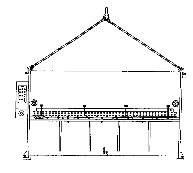
Lifting the Guillotine Shearing Machine
To safely lift this machine, only approved and secure wire ropes should be used at the two designated lifting points located on both sides of the machine frame.
Foundation
All our shears are designed to be freestanding, but a high-quality, reinforced concrete floor with a minimum thickness of 150mm is recommended.
Installation
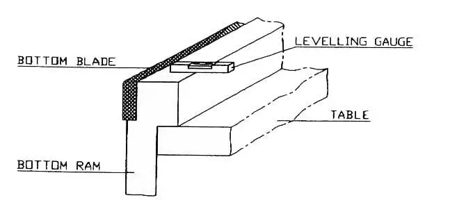
For proper operation, this machine must be properly leveled. To level the machine, place a level gauge at the plate hold-down area and ensure that it is accurate. Before leveling, prepare five pieces of base plate (minimum dimension of 150 x 150 x 9mm) under the machine’s feet to prevent the leveling screws from damaging the concrete floor.
After leveling, a cement grout mixture should be used to secure the machine in place.
Electrical Installation
Before connecting any electrical power, ensure that the local power supply is suitable for the machine. The power cable should be connected to the bottom left of the electrical panel to the R.S.T.E. terminal.
Note: Some guillotine shearing machines may require a neutral (N) wire.
EQUIPMENT STANDARD CONTROL DEVICE
| Start button |
To start the main motor running and control circuit |
| Stop button |
To stop the main motor running and control circuit |
| Auto/Man mode |
Select the working mode |
| Selector Switch |
In Auto mode:
-Rake angle adjustment function able
-Motorized back gauge function able
-Can command cut by foot pedal onlyIn Man mode:
-Rake angle adjustment not- Function able
-Motorized back gauge not-function able
-Command up and down of top blade carrier by push button ‘↑’ or ‘↓’ |
| Foot pedal |
Push to command cutting blade down and release to have top blade carrier rise in AUTO mode. |
| Illumination light |
Working light to shine at cutting blade area, operating at single phase power supply at 220V, 50Hz. |
STARTUP OF GUILLOTINE SHEARING MACHINE
Preparation of hydraulic shearing machine
Remove the squaring arm and foot pedal from the handguard area. Set up the squaring arm on the left side (close to the electrical panel) by bolting it down to the shearing machine table and two side holes.
STARTING THE SHEARING MACHINE
Push the ‘START’ button and release it. The motor ‘on’ indicator light should turn on. Then, set the mode selector from ‘MAN’ to ‘AUTO’ position. The top blade carrier will rise after a few seconds. If it does not, this indicates that the motor is running in the wrong direction. In this case, turn off the power supply, reverse one of the two phase wires, and start the motor again. The top blade carrier will rise and stop when it reaches the limit switch L/S 2.
RAKE ANGLE ADJUSTMENT
Put the selector switch in ‘AUTO’ mode. Rake angle adjustment is only available in this mode.
Press the ‘angle +’ button, the top blade carrier should rise to 3 degrees (three lights should turn on) and stop when it reaches limit switch L/S 7.
Press the ‘angle -‘ button, the top blade carrier should lower to 1 degree (one light should turn on) and stop when it reaches limit switch L/S 5.
The above confirms that the rake angle adjustment system is functioning properly.
SETTING UP SQUARING ARM
Start the motor and keep it in AUTO mode.
Press the ‘angle -‘ button until the rake angle reduces to 1 degree and stops by hitting limit switch L/S 5.
Switch the selector to ‘MAN’ mode.
Press the ‘↓’ button, the top blade will come down and intersect with the lower blade. Check that the point of intersection is about 300mm to 400mm from the start of the cut (LHS).
Use a reliable tri-square to measure against the top blade to adjust the squareness of the squaring arm using the two side bolts and nuts.
BLADE CLEARANCE ADJUSTMENT
At the rear of the shearing machine, there are two blade clearance adjustment levels on both sides of the machine, both with an indication of sheet thickness. The factory sets them at the lowest position during delivery, which is suitable for cutting mild steel plates 5 to 6mm (1/4 inch) thick. To adjust the settings, pull the locking sleeve and lift upward to the 1mm position. It will be heavier to set it to the top position (1mm) than the lower position (6mm) due to spring tension. Both sides of the blade clearance adjustment are factory set and should have similar tension.
MOTORISED BACKGAUGE
Put the selector switch in AUTO mode, the motorized back gauge only works in this mode. The factory has accurately set the motorized back gauge reading and it should correspond to the distance from the back gauge bar to the cutting edge. When you press the ‘+’ button, the back gauge bar moves towards the rear, the reading increases, and it stops when it reaches the maximum travel limit switch L/S 3. When you press the ‘-‘ button, the back gauge bar moves towards the front, the reading decreases, and it stops when it reaches the minimum travel limit switch L/S 4. The factory has set the parallelism of the back gauge, but it can be calibrated if needed. To remove the anti-rust coating prior to cutting, bring the back gauge bar to the rear.
BLADE CLEARANCE
Blade Clearance Table
| Quick blade setting |
Clearance |
For material thickness |
Blade |
Clearance |
| Top position |
1 to 2 mm |
( 1/24’’ to 1/12’’ ) |
0.05 mm |
(0.002”) |
| 2nd position |
3 to 4.5 mm |
( 1/8” to 3/16’’ ) |
0.3 mm |
(0.012”) |
| Lowest position |
5 to 6.5mm |
(5/24” to 13/48’’ ) |
0.6 mm |
(0.023”) |
- Check for Maximum Clearance
- Set blade clearance lever to lowest position.
- Put rake angle at 3 degrees in ‘AUTO’ mode.
- Switch selector to ‘MAN’ mode.
- Push ‘↓’ button to bring top blade carrier down to have top and bottom blade intercepting point at just before end of blade (RHS)
- Use a feeler gauge to check the clearance at the point of interception, it should be at 0.6mm (0.023”)
- Push ‘↑’ button to bring top blade carrier up until the interception point just before start of cutting
- Use a feeler gauge to check, it should be at 0.6mm (0.023”)
- Check for Minimum Clearance
- Switch selector switch to ‘MAN’ mode.
- Be sure that quick blade clearance levers are set at the 2nd position (3mm). Push ‘↓’ button until top blade carrier goes to the lowest position.
- Bring quick blade clearance levers to the top position (1mm). Push ‘↑’ button until interception point at end of the cut.
- Make measurement with the feeler gauge, it should be 0.05mm (0.002”). Push ‘ ↑ ’ button until the interception point at the start of the cut, take the measurement, it should read 0.05mm (0.002”).
- Attention
Only Experienced and Skilled Personnel Allowed
It is recommended that only experienced and skilled individuals perform blade clearance checks. It is also recommended that two people work together.
Proper Procedure
The back gauge should be set to its rearmost position (maximum out) before starting.
Safety First
Exercise extreme caution when setting or checking blade clearance as improper handling may result in excessive blade damage or injury to personnel.
MAINTENANCE
Lubrication and Hydraulic Oil
This guillotine shearing machine requires hydraulic oil grade 68. Only use this same grade of oil for refilling or replacement.
- FIAT-HTF 68
- ENERGOL HLP 68
- ESSO NUTO H68
- MOBIL-DTE OIL 26
- SHELL-TELLUS S68
- TOTAL-AZOLLA 68
Lubrication program
- After the initial 1500 working hours, change all the oil in the machine. It is important to drain all the oil from the oil tank to remove any impurities that may have entered during assembly.
- Replace the oil filter with the same grade of oil filter.
- Subsequently, change the oil every 5000 working hours.
- Lubricate all grease nipple points on the back gauge assembly every two weeks.
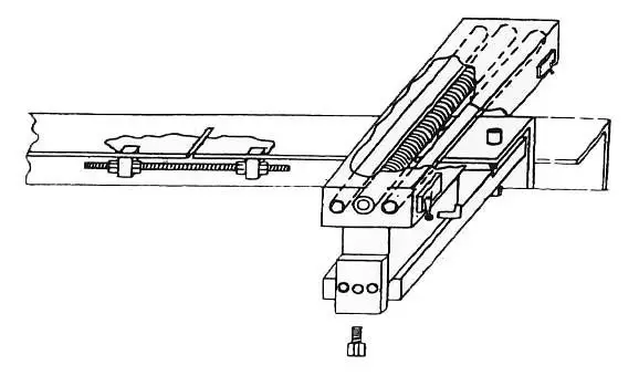
Back Gauge Calibration
The back gauge of the machine has been calibrated correctly at the factory. However, it may need to be recalibrated as necessary.
Procedure for Adjusting Parallelism of Back Gauge
- Always loosen the M14 screw before making any adjustments.
- To reduce the dimension of the back gauge, screw in the M8 screw and then tighten the two M6 screws.
- To increase the dimension of the back gauge, screw out the two M6 screws and then tighten the M8 screw.
- Tighten the M14 screws after the calibration is complete.
Shear Blade Replacement Procedure
- Both the top and bottom shear blades are interchangeable and identical. Set the blade clearance to its largest (lowest) position.
- Put the shearing machine in “AUTO” mode and remove wires “F” and “S” from the terminal block to prevent any unintended cutting commands while working on the machine.
- Turn off the machine. Remove the bottom blade first, then the top blade. Release all the small set screws on the top blade carrier.
- Clean the blades and blade housing/seat. Replace the top blade first, then the bottom blade.
- Tighten the small set screws on the top blade carrier if necessary to reduce blade clearance.
- Remember to check for minimum clearance and adjust the small set screws to close the blades as needed.
- Remember to reattach the wires “F” and “S” to their original positions before putting the machine back into operation.
CAUTION: Only qualified and experienced personnel should perform this task to prevent damage to the shear blades/machine or potential injury to personnel.
Grinding of Shear Blade
The shear blade is rectangular in shape and has four cutting edges. Regrinding is only necessary once all four edges have been used.
REMEMBER: Only grind the thickness, not the height of the blade.
After regrinding, it may be necessary to close the top blade carrier by tightening the tensioning bolt located near the quick blade clearance lever due to the loss of grind-off thickness of the shear blades.
WORKING SYSTEM
Hydraulic system (Refer to Hydraulic Circuit – Drg. 9.1 (b) )
When the foot pedal is pressed and held, valves C and D are energized, causing the plate clamps to descend.
The pressure switch triggers valve B to energize, which causes the top blade to descend and cut the material.
When the foot pedal is released at the end of the cut or at any point during the cut, valves A, D, and G are energized, causing the top blade to rise to the top dead center and be ready for the next cut.
To increase the rake angle, valves D and F are energized.
To decrease the rake angle, valves D and E are energized.
Electrical System
In Auto mode, the contactor R4 is energized during the idle state.
When the foot pedal is depressed and held, contactor R1 commands the plate clamps and blade to descend.
Upon release of the foot pedal for the upstroke, contactor R2 must be energized.
Contactor R3 (anti-repetition) is energized as long as the foot pedal is depressed during the upstroke of the top blade to prevent a second stroke of the top blade.
Contactor A1 moves the back gauge away from the cutting edge.
Contactor A2 moves the back gauge towards the cutting edge.
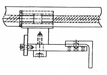
Motorized back gauge
The back gauge serves as a gauging device, stopping the plate to be cut when pushed into the Shear. It can be moved by powered or manual means, using a pair of accurate lead screws. In the RAS series machine, the readout is located in front of the machine and can be adjusted to 0.1mm increments. The back-stop bar can also be aligned for straightness by adjusting the setting bolts and counter-bolt within the bar itself. Regular lubrication is necessary, at intervals of once a week.
HYDRAULIC GUILLOTINE SHEARS TROUBLESHOOTING
Shearing Machine Cannot Start
- Check incoming power supply
- Check that Emergency Stop is release.
- Check fuse – 3 x 32A, 1 x 10A and 1 x 6A are still not fused.
- Check the transformer output
Shearing Machine Cannot Cut
- Check that selector is in Auto mode.
- Check that limit switch L/S 2 is engaged.
- Check that motor is rotated in a correct rotation.
- Check that foot paddle cable is not broken.
- Check that micro-switch inside foot paddle is working.
Ram Chattering on Down Stroke
- Counterbalance setting pressure is a little too high
- Just release the set screw a little to lower the setting
Shearing Machine Operate By Itself
- Be sure that the Micro-switch inside foot paddle is not damaged.
- Foot paddle cable may be shorted to each other.
Fuse F2, 10A Fused
- Transformers faulty, replace it
Fuse F3, 6A Fused
- Rectifiers faulty, replace it.
Plate Clamp Come down But Top Blade Carrier Not Working
- Pressure switch not working.
- Wire to pressure switch may be broken.
Hydraulic Guillotine Shears Drawings and Spare Parts List
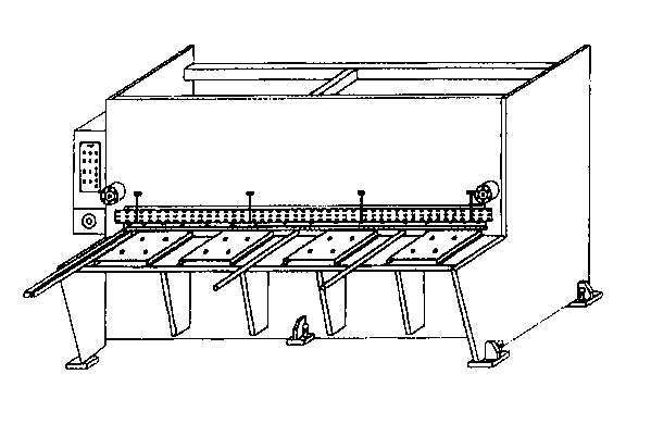
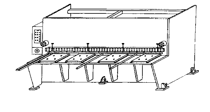
(A) FRONT VIEW
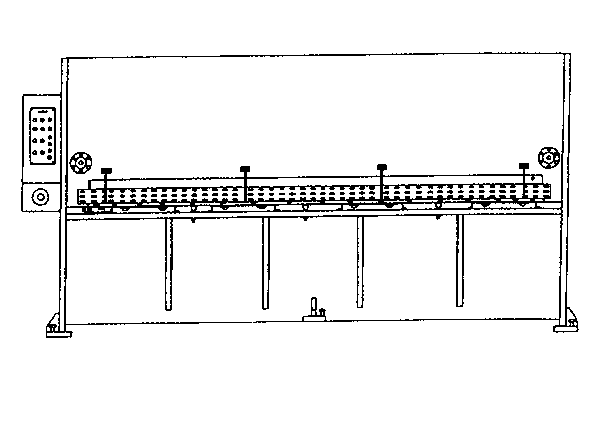
(B) REAR VIEW
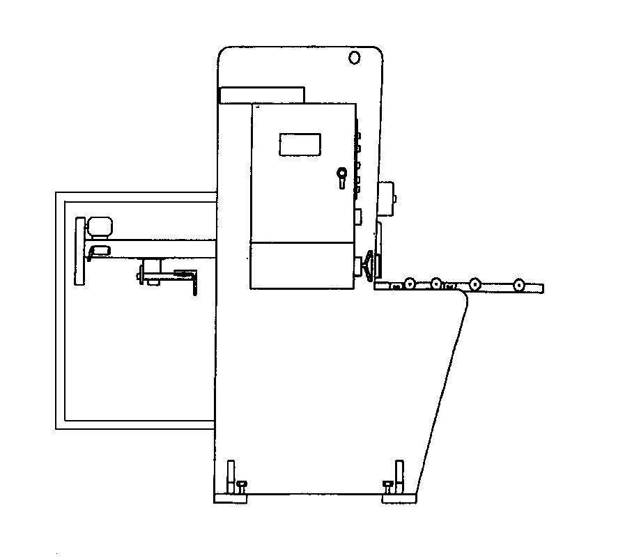
SIDE VIEW
LIFTING of Hydraulic Guillotine Shearing Machine
PLACING OF LEVELING GAUGE
NOTE: Ensure that the leveling gauge is not in contact with the blade and place it as indicated above.
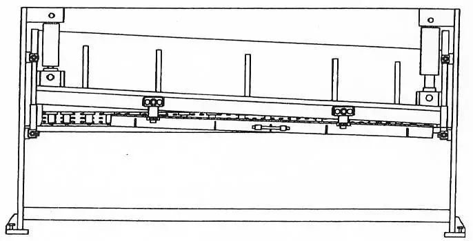
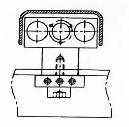
GUILLOTINE SHEARS BACK-GAUGE ASSEMBLY
SIDE VIEW
REAR VIEW
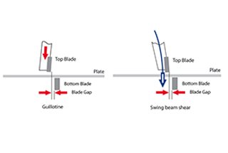
> Check out hydraulic swing beam shearing machine operation manual