Is your mechanical shearing machine not working as it should? In this guide, you’ll find detailed troubleshooting steps for common issues such as inconsistent shearing widths, surface straightness problems, excessive burrs, and more. Learn how to diagnose and fix these problems to keep your equipment running smoothly and efficiently. This article provides practical solutions to ensure precision and reliability in your shearing operations.
1. Transmission principle of mechanical shearing machine
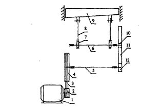
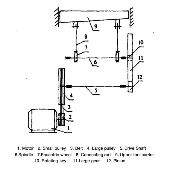
As depicted in Figure 1, the motor rotates the large pulley through the use of a small pulley. The large belt pulley, in turn, causes the big and small gears to rotate via the drive shaft. The big gear drives the rotation of the eccentric wheel through the main shaft.
Finally, the eccentric wheel moves the slider (upper tool carrier) up and down, resulting in shearing, through the connecting rod.
Fig. 1 Schematic diagram of the transmission principle of shearing machine
2. Analysis and troubleshooting of mechanical shearing machine
2.1 The width of shear parts is not consistent, and the repeated accuracy of batch parts is out of tolerance.
Cause Analysis:
The incorrect positioning of the baffle plate and the large gap between it and the shear blade is causing movement during locking.
The movement of the baffle plate is not synchronized on both sides, resulting in a large gap between the transmission parts.
Improper adjustment of the pressing spring force leads to uneven pressure and movement of the plate material during shearing.
The deformation of the baffle plate and the straightness being out of tolerance is causing inaccurate positioning of parts.
The gap between the upper and lower moving guide rail of the shear blade slider and the pressing plate is not properly adjusted.
Elimination Method:
The gap should be eliminated to make the distance between the baffle plate and the shear blade consistent. The repeated positioning error should be within 0.03/1000 after locking.
The gap between transmission parts should be eliminated.
The gap between the pressing beam and the sheet metal should be adjusted to approximately 10mm, and the compression force of the spring should be set to 11kn and kept even on both ends.
The flatness and straightness error of the baffle plate should be repaired to be within 0.02/1000.
The gap between the guide rail and pressing plate should be adjusted to be within 0.03mm.
2.2 The surface straightness of shear parts is out of tolerance, with convex or concave phenomenon.
Cause Analysis:
The large horizontal error in the installation of the worktable is causing distortion in the equipment.
The large flatness error of the vertical supporting surface of the upper and lower scissors is causing the straightness of the shear blade to exceed the tolerance after fastening.
The movement of the shear blade up and down, the twisting of both sides of the guide rail surface (not in the same plane), or the wear on the guide rail is causing the straightness to be out of tolerance.
Elimination Method:
Re-align the installation level of the equipment to ensure an accuracy of 0.05/1000.
Correct the fitting bearing surface of the upper and lower shear blades and ensure a flatness of 0.03/1000.
Repair and scrape the guide rail of the bed to ensure both ends are parallel to each other and the straightness is guaranteed to be between 0.02/1000.
2.3 The burr at the cutting part of the part is too large.
Cause Analysis:
The gap between the upper and lower shear blades is not properly adjusted.
The cutting edge has become worn and dull.
The gap between the upper and lower shear blades is uneven, resulting in burrs appearing at the larger gap.
Elimination Method:
Adjust the gap to be between 5% to 8% of the sheet thickness.
Replace or sharpen the cutting edge.
Adjust and inspect every 500mm to ensure the gap is even and does not exceed 0.05mm.
2.4 Narrow strip is sheared, and the parts are twisted and deformed.
Cause Analysis:
The clearance of the slide guide surface of the shear blade is set too large.
Both sides of the guide surface of the shear blade slider are twisted or have become out of tolerance due to wear.
Elimination Method:
Adjust the pressing plate to ensure that the clearance of the guide rail on both sides is within 0.03mm.
Scrape the slide block and bed guide rail so that the contact surface of the slide block and the bed guide rail is (25 x 25) mm2 with 12 points, and the straightness is within 0.02/1000.
2.5 There are historical materials and pushing materials in the shear narrow strip parts
Cause Analysis:
The plane of the baffle plate is inclined and not perpendicular to the horizontal plane.
The parallelism of the vertical support surface fitted with the upper blade is out of tolerance.
Elimination Method:
Repair the plane of the baffle plate to ensure it is perpendicular to the horizontal plane.
When the upper turret moves downward, adjust the distance between the two vertical surfaces that fit the upper blade and the lower blade to ensure an error of within 0.02/1000.
2.6 The clutch of single stroke fails to engage and the shear blade does not act.
Cause Analysis:
The wear on the rotating part of the rotary key and the triangular notch of the buffer sleeve is causing the clutch to slip when engaging with the crankshaft.
The control spring of the rotary key is broken or loose, causing insufficient force and a lack of flexibility in the rotary key’s movement.
The brake band and brake disc are adjusted too tightly, resulting in clutch slipping.
Elimination Method:
Replace the rotary key and repair the triangular notch of the buffer sleeve to ensure the rotary key moves freely and the combination is secure when the triangular notch is engaged.
Replace the spring and adjust the tension to ensure the rotary key moves freely.
Adjust the tightness of the brake band.
2.7 Continuous cutting occurs during single stroke.
Cause Analysis:
The pinhead and control block of the rotary key handle are worn, causing the pinhead of the rotary key to not lock in place.
Improper adjustment of the control plate’s position is preventing the pinhead of the rotary key from locking in place.
Elimination Method:
Repair the pinhead of the rotary key by welding and restoring it to its original design size.
Adjust the mutual position of the control block and repair it.
2.8 There is an impulse phenomenon and abnormal noise in one stroke of the shear slider.
Cause Analysis:
The rotary key does not fit properly with the triangular groove of the buffer sleeve, causing wear and an improper rotation angle of the rotary key. This results in impact and noise during the reciprocating movement of the cutting edge.
The spring force of the rotary key is too weak to hold it in place, causing impact when the slider moves from top to bottom.
The balance spring force of the up and down movement of the shear blade slider is not properly adjusted.
Elimination Method:
Repair the contact surface between the rotating part of the rotary key and the triangular groove of the buffer sleeve to ensure the key rotates freely and reliably.
Adjust or replace the spring to provide sufficient force.
Adjust the spring force until the slider moves smoothly without shock or vibration.
2.9 When the flywheel is idling, the clutch makes a rhythmic sound.
Cause Analysis:
The rotating part of the rotary key does not fully disengage from the triangular groove of the buffer sleeve, resulting in a sound after one revolution.
Elimination Method:
Grind the mating surface of the rotary key and adjust its position to resolve the issue.
As the founder of MachineMFG, I have dedicated over a decade of my career to the metalworking industry. My extensive experience has allowed me to become an expert in the fields of sheet metal fabrication, machining, mechanical engineering, and machine tools for metals. I am constantly thinking, reading, and writing about these subjects, constantly striving to stay at the forefront of my field. Let my knowledge and expertise be an asset to your business.
Have you ever wondered how those massive steel plates are cut with such precision? Enter the world of hydraulic shearing machines - the unsung heroes of the metal fabrication industry.…
Ever wondered what makes the perfect shear blade? In this article, we'll explore the fascinating world of die steels, from cold-work to hot-work varieties. You'll uncover the secrets behind their…
Ever wondered how powerful machines transform raw metal into precise, usable parts? This article unveils the secrets of the hydraulic shearing machine, a marvel of engineering. Learn how it cuts…
Ever wondered how to maximize the efficiency and safety of your shearing machine? This guide delves into essential tips for operating and maintaining these powerful tools. From choosing the right…
Ever wondered who the top players are in the shearing machine industry? In this article, we'll explore the leading shearing machine manufacturers in China for 2023. You'll discover companies that…
Have you ever wondered how precision and efficiency come together in industrial cutting? This article explores the fascinating world of guillotine shears, detailing their advantages and challenges. Learn how mechanical…
Ever wondered why some metal sheets come out perfectly flat while others warp and distort? This article reveals the secrets behind cutting forces in rotary plate shears. You'll learn how…
Sheet metal shears, as the name implies, is a machine used for cutting sheet metal. The material selection is based on the general Q235 plate. If cutting Q345 plate, then…
Have you ever wondered how factories achieve precise metal cuts with minimal effort? Enter the notching machine, a versatile tool used to cut metal plates at various angles. This article…