5 Best Material for Gears Compared
Gears are the unsung heroes of the mechanical world, quietly working behind the scenes to keep machines running smoothly. But have you ever wondered what materials these critical components are…
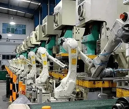
Imagine a factory floor where robots handle the heavy lifting, precise placement, and swift transitions of sheet metal with flawless coordination. This is the world of robotic press automation lines. In this article, we’ll explore the essential components that make these systems so efficient and reliable. You’ll learn about the critical roles of stamping robots, control systems, and various automated devices, providing insights into how these advanced technologies streamline production and enhance safety.
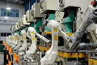
A typical robotic stamping line typically consists of the following components:
The specific arrangement of these components can be customized based on the production workshop’s layout. For instance, the depalletizing car can be positioned either parallel or perpendicular to the punching line.

Stamping production robots require a number of essential features including a high payload capacity, precise movement trajectories, and reliable performance. Additionally, these robots must also possess certain characteristics such as frequent start-stop movements, a wide operating range, the ability to handle large workpieces, and ample turning space.
Manufacturers of stamping robots have made various improvements over traditional handling robots. These advancements include increased motor power and gear specifications, longer robot arms, and the widespread use of scaffold-mounted structures.
The control system for a roboticized automation press line must integrate a variety of components including presses, robots, depalletizers, cleaners, oilers, centering devices, double material detection devices, visual recognition systems, various conveyor belts, synchronous control systems, safety protection systems, and large screen displays. The system should also have the capability to integrate seamlessly into the plant’s Manufacturing Execution System (MES).
To effectively manage the integration of so many intelligent control systems, Ethernet and industrial fieldbus secondary network systems are commonly used. In some cases, the fieldbus system may also include a safety bus for added security.
Currently, there are three prevalent depalletizing systems:
The design feature of these systems is that the pallets are placed on a hydraulic lifting trolley that can be moved. The height of the stacked material is monitored by photoelectric sensors and controlled by hydraulic systems, ensuring that it stays consistent. The magnetic spreader operates either pneumatically or electrically and automatically moves close to the stacked material.
A matrix of vacuum chucks driven by a cylinder is used to destack the material, and the vacuum chucks move vertically. Finally, the dismantled sheets are transported using magnetic belts.
The design feature of this system is that the stacked material is placed on a movable destacking trolley. The height of the stacked material is not controlled, but the height at which the robot suctions the material is automatically adjusted based on the calculated thickness of the sheet during the destacking process.
The bracket for the magnetic divider is mounted on the destacking trolley. The rack is capable of translation and has multiple freely adjustable joints, allowing the magnetic spreader to be manually positioned against the edges of the stock during stock changes.
Vacuum suction sets and double strength testing sensors for destacking are located on the gantry robot tooling. The robot then separates the sheet into individual pieces and places them on a retractable transition belt for further transportation.
The design feature of this system is that the stacked material is placed on a movable destacking trolley. The height of the stacked material is not regulated, but the robot automatically adjusts the suction height based on the calculated thickness of the sheet during the depalletizing process.
The bracket for the magnetic divider is mounted on the destacking trolley, which can be translated and has multiple adjustable joints that can rotate freely. When changing the stacked material, the magnetic divider must be manually positioned against the edges of the stacked material.
Vacuum suction sets and double strength testing sensors for destacking are located on the gantry robot tooling. The robot then separates the sheet into individual pieces and places them on a retractable transition belt for further transmission.
An extendable belt conveyor is utilized to transfer individual sheets after the destacking process is complete. The conveyor’s speed can be adjusted to provide the necessary movement for the sheet metal as it travels through the washing machine.
The speed of the belt conveyor is typically regulated through frequency conversion to ensure proper synchronization with the washing machine and oiler. The length of the belt can be adjusted to accommodate for the space when the sheet metal is not being cleaned and the cleaning machine is inactive.
Sheet metal cleaning can be divided into two types: online cleaning and offline cleaning.
Online cleaning is best suited for enterprises with high production volumes. To accommodate the size of the car’s overall circumference, the online cleaning machine is usually 4.2m wide.
In contrast, offline cleaning is ideal for enterprises with low single-model output in the early stages of production. One sheet metal cleaning line can support 2 to 3 punching lines, and the offline cleaning machine is typically 2m wide.
The cleaning machine comprises several components, including a roller system with feed, brush, and squeezing rollers, a power and transmission system, a hydraulic adjustment mechanism, a cleaning filter system, a cluster nozzle assembly, an oil mist collector, a lubrication system, a walking mechanism, and an electrical control system.
It is mainly used to clean standard plates, as well as uncoated, galvanized, and aluminum sheets and coils.
The washing machine has a self-propelled mechanism and can be easily moved on the ground track when not in use. The guide roller, brush roller, and squeezing roller each have independent pressure adjustment and frequency conversion drive capabilities.
By adjusting the pressure and speed accurately, the worn and repaired roller system remains in sync with the production line. The squeezing roller uses a non-woven laminated cloth roller that provides excellent squeezing and tensioning performance, and has anti-scratch and self-healing functions.
The cleaning oil tank is equipped with a heating system, allowing the cleaning medium to be used at different temperatures to achieve optimal oiling results. The electrical system is controlled by a PLC with fieldbus communication capabilities, and parameters and faults can be managed via the touch screen man-machine interface.
To guarantee the quality of the sheet during high-speed drawing and forming, the local application of drawing oil to the sheet prior to stamping and forming is a common practice in automotive plants. It is suitable for use in automated stamping lines with oiling machines.
The oiler is primarily utilized for the oiling process before sheet metal drawing. It consists of a gun unit, an oil supply and preservation unit, an air supply unit, a sheet conveying unit, an oil mist collection unit, an electrical control unit, and the machine itself.
The oiler has a walking mechanism, allowing it to be moved offline when oiling is not required. The nozzles are digitally controlled to ensure accurate positioning of the oil film on the sheet and uniform film thickness.
Regardless of changes in ambient temperature, the oil supply and preservation units remain in a standby state, ensuring a constant oil temperature to achieve optimal results.
To ensure accurate placement of the sheet in the mold, it is necessary to align the sheet before the robot picks it up. There are three commonly used centering devices: gravity centering device, mechanical centering device, and optical centering device.
Gravity Centering Device:
The sheet metal is positioned through gravity on a ball-filled inclined surface. The table is equipped with sheet-in-place inspection and double material inspection.
The gravity centering device is suitable for direct placement by the robot, but not for automatic lines with washing and oiling machines.
Mechanical Centering Device:
The sheet metal is moved to the block by a magnetic leather bag, and three cylinders drive the feeder to push it towards the center for precise positioning.
All feeder positions can be taught and programmed, and the centering device has sheet material in-position detection and double-material detection.
It can meet the high-speed centering requirements for various sheet materials and a dual-center design can be used for simultaneous processing of two-piece or dual-mode parts.
Optical Centering Device:
This is a recent technological development that uses video processing software to automatically adjust the position of the sheet metal by taking pictures and adjusting the robot’s trajectory.
It not only meets the requirement for accurate placement of the sheet metal into the mold, but also eliminates the complexity of the mechanical centering device.
The optical centering device essentially uses a magnetic belt conveyor with sheet metal reaching detection and double strength detection. Compared to the mechanical centering device, it significantly reduces costs.
A standard six-axis tree robot for stamping has a production rate of 8 pieces per minute. In recent years, robot manufacturers and system integrators have developed a seven-axis to further increase productivity.
With the addition of the seventh axis, the production rate of automated robotic stamping lines can be increased to 12 pieces per minute, making the productivity of robot-automated stamping lines comparable to high-speed lines using expensive dedicated robots.
The production pace of the automated stamping line can surpass 10 pieces per minute, putting excessive demands on the end-of-line palletizing station beyond the labor limit.
To accommodate the high-pace output, the stamped parts need to be diverted first. Then, they can be manually or robotically packaged into racks, before finally being removed by a forklift.

As the founder of MachineMFG, I have dedicated over a decade of my career to the metalworking industry. My extensive experience has allowed me to become an expert in the fields of sheet metal fabrication, machining, mechanical engineering, and machine tools for metals. I am constantly thinking, reading, and writing about these subjects, constantly striving to stay at the forefront of my field. Let my knowledge and expertise be an asset to your business.