A Comprehensive Guide to Hydraulic Systems: Principles, Components, & Applications
Have you ever wondered how powerful machines effortlessly perform complex tasks? The answer lies in their hydraulic systems – the unsung heroes of modern engineering. In this blog post, we’ll delve into the fascinating world of hydraulics, exploring its principles, advantages, and diverse applications across industries. Get ready to discover how this remarkable technology is revolutionizing the way we live and work.
The hydraulic system is a transmission system that utilizes liquid as a working medium and utilizes the internal pressure of the liquid to transfer, convert, and control power (or energy) based on Pascal’s principle in fluid mechanics.
The hydraulic system is the key to controlling mechanical equipment to perform various actions, and its technical level and product performance will directly affect the automation level and reliability of the mechanical equipment.
Characteristics of hydraulic systems:
Advantages:
1. The hydraulic transmission device operates smoothly and can move steadily at low speeds. When the load changes, its movement stability is relatively stable, and it can easily achieve stepless speed regulation during movement, and the regulation ratio is large, generally up to 100:1, and the maximum can reach 200:1.
2. Under the same power, the hydraulic transmission device has a small volume, light weight, and compact structure, so its inertia is small and the switching rate is high.
3. The control and regulation of the hydraulic transmission device are relatively simple and easy to operate.
Disadvantages:
1. The hydraulic transmission device uses liquid as the transfer power medium, and there will be unavoidable leaks between the relative motion parts, causing volume loss.
At the same time, due to the compressibility of the body, it is generally not easy to use in the case of very strict requirements for the transmission ratio (such as thread and gear processing).
To reduce leaks, the manufacturing accuracy of hydraulic components is required to be high.
2. The flow of oil in pipelines and through relevant hydraulic components will result in pressure loss, mechanical friction loss and viscosity friction loss between moving parts and flowing oil molecules, and volume loss caused by leaks, which will reduce the overall efficiency of the hydraulic system.
3. Changes in oil temperature will cause changes in oil viscosity, which will affect the stability of the hydraulic system, so it is difficult to use hydraulic transmission in low and high temperature environments.
4. Due to the small clearance between the hydraulic device and the relative motion parts, the hydraulic system is sensitive to oil pollution, and there must be facilities to prevent oil pollution and good filtration.
Importance of hydraulic systems in various industries
1. Application of Hydraulic Technology in Industry
Hydraulic technology is generally applied to heavy, large, and very large equipment, such as rolling mill hydraulic systems and continuous casting hydraulic systems in the metallurgical industry, and high-speed response scenarios in military industry, such as aircraft rudder control, ship rudder control, and high-speed response follow-up systems.
2. Application of Hydraulic Technology in Wind Power Generation
The hydraulic system is mainly used to regulate the blade moment, damping, stop, and brake status of the wind turbine.
The wind turbine in wind power generation has many rotating components. The nacelle rotates in the horizontal plane and rotates with the wind wheel along the horizontal axis to generate power.
In the variable blade wind turbine, the blades of the wind wheel must rotate around the center axis of the root to adapt to different wind conditions. When the wind turbine is stopped, the blade tip must be thrown to form a damping.
3. Application of Hydraulic Technology in Military Field
Modern warfare is a local war under high-tech conditions. High-tech is widely used in military fields and various new weapons and technological weapons are put into the battlefield, making the suddenness and destructiveness of the war unprecedentedly increased, and the dependence of the war on hydraulic technology further increased.
4. Application of Hydraulic Technology in Engineering Machinery Field
Hydraulic variable high-frequency impact hammers have a very good prospect of application in geological exploration and ocean fields.
The excitation frequency of general hydraulic variable high-frequency impact hammers is 10-20 Hz, while the latest hydraulic variable high-frequency impact hammers recently introduced in Japan can reach 60 Hz.
And in construction, the excitation frequency and amplitude can be changed according to the actual situation of the site, and the optimization of vibration and working conditions can be realized.
5. Application of Hydraulic Technology in Underwater Operations Field
With the deepening of human exploration of the seabed in today’s society, the development of underwater robot technology is also rapid, and its functions are no longer limited to simple observation types.
People’s eyes are focused on operational underwater robots, which are obviously more development space and market. In the entire operation, the mechanical hand is the most widely used and complicated component.
The flexible mechanical hand helps the operational underwater robot to complete various underwater operation tasks with excellent results.
6. Application of Hydraulic Technology in Mining Machinery Field
The new hydraulic excavator not only has the advantages of light weight, small size, compact structure, etc., but also has a series of advantages in the transmission process, such as stability, easy operation, and easy to achieve stepless speed regulation and automatic control.
In addition, the performance is developing in the direction of high efficiency, high reliability, safety, energy conservation, and automation and intelligence.
7. Application of Hydraulic Technology in Elevators
Hydraulic elevators have the advantages of large load capacity and smooth operation, but the way they operate is different.
The R-layer stacked guide rail is suitable for the movement form of the ladder hydraulic elevator, and the composite pulley group is suitable for the movement form of the hydraulic elevator.
Principles of Hydraulic Systems
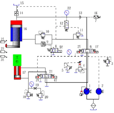
Schematic diagram of the hydraulic system of 3150K universal hydraulic press
1. Starting
All electromagnets are off and the output oil of the main pump passes through the mid-unloading of valves 6 and 21.
2. Fast descent of the main cylinder
Electromagnets 1Y and 5Y are energized, valve 6 is in the right position, and the control oil passes through valve 8 to open the solenoid-controlled one-way valve 9.
Inlet path: pump 1 valve 6 right position valve 13 main cylinder upper chamber.
Return path: main cylinder lower chamber valve 9 valve 6 right position valve 21 mid-position oil tank.
The main cylinder slide rapidly descends under the action of its own weight, and pump 1, although in the maximum flow state, still cannot meet its needs, so the oil in the upper chamber of the oil tank 15 enters the upper chamber of the main cylinder through the charging valve 14.
3. Slow approach to the workpiece and pressure increase of the main cylinder
When the main cylinder slide descends to a certain position and triggers the stroke switch 2S, 5Y is de-energized, valve 9 closes, and the oil in the lower chamber of the main cylinder returns to the oil tank through the back pressure valve 10, valve 6 right position, and valve 21 mid-position.
At this time, the pressure in the upper chamber of the main cylinder increases, valve 14 closes, and the main cylinder slowly approaches the workpiece under the action of the pressure oil supplied by pump 1.
After contacting the workpiece, the resistance suddenly increases, and the pressure further increases, causing the output flow of pump 1 to automatically decrease.
4. Pressure maintenance
When the pressure in the upper chamber of the main cylinder reaches the predetermined value, the pressure relay 7 sends a signal, causing 1Y to be de-energized, valve 6 to return to the mid-position, the upper and lower chambers of the main cylinder to be closed, and the cone surfaces of one-way valve 13 and charging valve 14 to ensure good sealing, thus maintaining the pressure of the main cylinder.
The pressure maintenance time is adjusted by the time relay. During pressure maintenance, the pump is unloaded through the mid-position of valves 6 and 21.
5. Pressure Release, Main Cylinder Return and Pressure Maintenance End
When the time relay sends out a signal, solenoid 2Y is energized and valve 6 is in the left position.
Due to the high pressure in the main cylinder’s upper chamber, the hydraulic pilot valve 12 is in the upper position and the pressure oil opens the external control sequence valve 11, allowing the output oil from pump 1 to return to the oil tank through valve 11.
Pump 1 operates under low pressure, which is not enough to open the main valve core of the charging valve 14, but instead opens the unloading valve core of the valve, allowing the oil in the main cylinder’s upper chamber to be released back to the upper oil tank through the unloading valve opening, and the pressure gradually decreases.
When the pressure in the main cylinder’s upper chamber has dropped to a certain level, valve 12 returns to the lower position, valve 11 closes, and the pressure of pump 1 increases, causing valve 14 to fully open. At this time, the oil inlet route is:
pump 1 to valve 6 left position to valve 9 to the main cylinder’s lower chamber. The oil return route is:
the main cylinder’s upper chamber to valve 14 to the upper oil tank 15, realizing the rapid return of the main cylinder.
6. Main Cylinder Stops in Place
When the main cylinder’s slider rises to trigger travel switch 1S, solenoid 2Y loses power and valve 6 is in the middle position, sealing the main cylinder’s lower chamber with the hydraulic one-way valve 9, causing the main cylinder to stop in place and not move, with the output oil from pump 1 being unloaded through valve 6 and 21 in the middle position.
7. Lower Cylinder Extrusion and Retraction
When 3Y is energized, valve 21 is in the left position. The oil enters the lower cylinder through the following path: pump 1, valve 6 in the center position, valve 21 in the left position, and the lower cylinder bottom cavity.
The oil returns to the oil tank through the following path: the upper cavity of the lower cylinder, valve 21 in the left position. The lower cylinder’s floating sleeve rises, causing the extrusion.
When 3Y loses power, 4Y is energized, and valve 21 is in the right position, causing the lower cylinder’s piston to descend and retract.
8. Floating Pressure Edge
Key Components of Hydraulic Systems
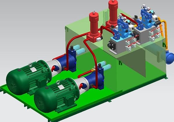
A hydraulic system typically consists of the following components:
Energy Source:
This component converts the mechanical energy from an electric motor into pressure energy in a fluid, such as various types of hydraulic pumps.
Actuators:
This includes various hydraulic cylinders and motors, which convert the pressure energy of the fluid into mechanical energy to drive the working components.
Control and Regulation Components:
This includes various pressure valves, flow valves, and directional valves, which regulate and control the pressure, flow, and flow direction of the fluid in the hydraulic system to meet the requirements of the working component for force (torque), speed (rotation), and motion direction (motion cycle).
Auxiliary Components:
All other components outside of the above three components are known as auxiliary components, including oil tanks, oil pipes, pipe joints, oil filters, accumulators, pressure gauges, heaters (coolers), and more.
These play an important role in ensuring the reliability and stability of the hydraulic system.
In addition, there is hydraulic oil, which is the transmission medium.
Applications of Hydraulic Systems
Hydraulic technology has greatly improved work efficiency with its iteration and updating of traditional equipment.
Currently, hydraulic technology has been integrated into the renovation of machinery and gradually replaced traditional technology as a core part, indicating the future development of the machinery industry.
In which industries is the hydraulic system used? Let’s take a look together.
In the machine tool industry, hydraulic systems of hot-working machine tools include die-casting machines, injection molding machines, hydraulic presses, punches, and fast forging machines.
Cold-working machine tools include combined machine tools, lathes, and various profile machine tools.
2. Construction machinery
Hydraulic transmission (hydraulic system) is widely used, such as excavators, tire loaders, car cranes, crawler bulldozers, tire cranes, self-propelled dump trucks, flatbed machines, vibratory rollers, etc.
3. Automotive industry
Hydraulic technology (hydraulic system) is used for hydraulic off-road vehicles, hydraulic dump trucks, hydraulic aerial work vehicles, and fire trucks.
4. Agricultural and forestry machinery
Hydraulic systems control farm implements on harvesters and tractors. Hydraulic systems control various movements of wood in wood container machinery. Artificial board hot presses are also operated with hydraulic systems.
5. Chemical and textile machinery
In chemical and textile machinery, hydraulic systems are used for plastic injection molding machines, rubber machinery, paper machines, leather smoothing machines, soap grinding machines, ceramic waste molding machines, spinning machines, and spinning machines of textile machinery.
6. Energy industry
Machinery with hydraulic systems used in the energy industry include drilling platforms, underwater oil extraction machines, drills, hoists, coal mining machines, mining machines, hydraulic supports for mining, power generation equipment, etc.
7. Metallurgical industry
In the metallurgical industry, hydraulic systems are used for blast furnace feeding machines, steelmaking furnace control systems, ladle turret machines, rolling mill down-pressure systems, roller bending balance systems, strip deviation control systems, etc.
8. Shipbuilding industry
Hydraulic technology (hydraulic system) is widely used in the shipbuilding industry, such as all-hydraulic dredgers, salvage ships, pile-driving ships, oil production routes, water wings, air cushion ships, ship auxiliary equipment, etc.
9. Small and medium-sized machinery parts processing technology
For example, various small and medium-sized metal parts designed for the metal parts industry.
Hydraulic presses are commonly used for pressure forming of these metal machinery parts, including extrusion forming, die pressing, cold and hot die forging, and free forging of metal profiles.
This process belongs to the manufacture of specific products, such as the processing technology of rubber products, SMC molding technology, and the heat forming of automotive interior parts.
The advantages of hydraulic presses in these devices are also very obvious.
Maintenance and Troubleshooting
Pressure Loss
Due to the viscosity of the liquid and the unavoidable frictional forces in the pipeline, a certain amount of energy will inevitably be lost as the liquid flows. This energy loss is mainly manifested as pressure loss. There are two types of pressure loss: along the path and local.
The pressure loss along the path is the loss of pressure due to friction as the liquid flows through a straight pipe with a constant diameter for a certain distance.
Local pressure loss is caused by the sudden change in the cross-sectional shape of the pipeline, the change in the direction of the liquid flow, or other forms of liquid resistance.
The total pressure loss is equal to the sum of the pressure losses along the path and the local pressure loss. Because pressure loss is inevitable, the rated pressure of the pump should be slightly higher than the maximum working pressure required by the system.
Generally, the maximum working pressure required by the system is multiplied by a factor of 1.3-1.5 to estimate the rated pressure.
Flow Loss
In a hydraulic system, there are relative moving surfaces between each compressed component, such as the inner surface of a hydraulic cylinder and the outer surface of a piston. Because there must be relative motion, there is a certain gap between them.
If one side of the gap is high-pressure oil and the other side is low-pressure oil, the high-pressure oil will flow through the gap to the low-pressure area, causing leakage.
At the same time, due to imperfect sealing of the hydraulic components, some oil will also leak to the outside. The actual flow rate is reduced due to this leakage, which is what we call flow loss.
Flow loss affects the motion speed, and leakage is difficult to completely avoid, so the rated flow rate of the pump in the hydraulic system should be slightly higher than the maximum required flow rate during system operation.
Usually, the maximum required flow rate of the system can be multiplied by a factor of 1.1-1.3 to estimate the rated flow rate.
Hydraulic Shock
Cause: When the liquid flows in a hydraulic system, the switching of the executing components and the closing of the valves can cause an instantaneous pressure peak due to inertia and the insufficiently sensitive reaction of some hydraulic components, which is called hydraulic shock. Its peak value can exceed several times the working pressure.
Harm: It can cause vibration and noise; make pressure components such as relays and sequence valves produce incorrect actions, and even damage some components, sealing devices, and pipelines.
Measures: Find out the cause of the shock and avoid a sharp change in the flow rate. Delay the time for the change in speed, estimate the pressure peak value, and take corresponding measures.
For example, the combination of flow switching valves and solenoid switching valves can effectively prevent hydraulic shock.
Cavitation
Phenomenon: If air infiltrates into the hydraulic system, the bubbles in the liquid will quickly burst under high pressure when they flow to the high-pressure area, causing local hydraulic shock and generating noise and vibration.
In addition, because the bubbles destroy the continuity of the liquid flow, the oil’s ability to flow through the pipeline is reduced, causing fluctuations in flow rate and pressure, and affecting the service life of the hydraulic components.
Cause: Hydraulic oil contains a certain amount of air, which can be dissolved in the oil or mixed in the form of bubbles.
When the pressure is lower than the air separation pressure, the air dissolved in the oil separates out and forms bubbles.
When the pressure drops below the oil’s saturated vapor pressure, the oil will boil and produce a large number of bubbles. These bubbles mixed in the oil form a discontinuous state, which is called cavitation.
Location: Air pockets are easy to form at the oil suction port and oil suction pipe below atmospheric pressure.
When the oil flows through small gaps such as throttling orifices, the pressure drops due to the increase in velocity, which can also cause air pockets.
Harm: Bubbles move with the oil to the high-pressure area and burst rapidly under high pressure, causing a sudden decrease in volume.
The surrounding high-pressure oil flows in to supplement it, causing local instantaneous shock, a rapid increase in pressure and temperature, and producing strong noise and vibration.
Measures: The structural parameters of the hydraulic pump and the oil suction pipeline should be correctly designed to avoid narrow and sharply curved oil passages and prevent the formation of low-pressure zones.
Reasonable selection of mechanical materials, increasing mechanical strength, improving surface quality, and enhancing corrosion resistance.
Cavitation Erosion
Cause: Cavitation is often accompanied by cavitation erosion, and the oxygen in the bubbles produced in the air pockets can corrode the surface of metal components.
We call this corrosion caused by cavitation as cavitation erosion.
Location: Cavitation erosion may occur in oil pumps, pipelines, and other devices with throttling devices, especially in oil pump devices, where this phenomenon is most common.
Cavitation erosion is one of the causes of various faults in hydraulic systems, especially in high-speed and high-pressure hydraulic equipment, where it should be given particular attention.
Harm and measures are the same as for cavitation.
Future Developments in Hydraulic Systems
1. Emergence of the Trend of Import Substitution for High-end Hydraulic Products
Although China’s hydraulic industry has developed rapidly, most hydraulic component manufacturing enterprises have been small in scale with limited innovation capabilities.
Hydraulic products are mainly concentrated in the mid-to-low-end market, and there is a significant overcapacity of ordinary hydraulic components, leading to fierce competition in low-price and low-level products.
Due to the lagging development of high-end hydraulic components compared to downstream equipment manufacturing industries, domestic mainframe manufacturers have long relied on imports for high-end hydraulic components.
In recent years, with the development of the industry and the technological innovation of enterprises, domestic hydraulic component manufacturers have gradually made breakthroughs in technology and processes, resulting in improved product performance.
Some high-quality enterprises in the hydraulic industry have gradually broken the dependence of domestic mainframe manufacturers on international brands with their high cost-performance ratio and regional advantages, continuously expanding their market share.
With the outbreak of the COVID-19 pandemic in 2020, international trade was hindered to some extent, and domestic mainframe manufacturers actively sought domestic enterprises for matching, promoting the process of import substitution and providing new opportunities for domestic hydraulic component manufacturers.
2. Integration of Hydraulic Technology with High-tech Achievements”
In recent years, the integration of hydraulic technology with new technologies such as computer information technology, microelectronics technology, and automatic control technology has promoted the development level of hydraulic systems and components.
In the short term, the possibility of breakthrough changes in hydraulic technology is low, but hydraulic technology will continue to improve, specifically in terms of: miniaturization, lightweight, and modularization of hydraulic components; greening of production processes; integration and integration of hydraulic systems.
1) Miniaturization, Lightweighting, and Modularization of Products
Miniaturization, lightweighting, and modularization are inevitable trends in the entire hydraulic industry.
Miniaturization can be achieved by redesigning the layout and structure of components, and it helps to improve the response speed of hydraulic systems.
Lightweighting of hydraulic components can be achieved through material selection and technological updates, reducing downstream equipment energy consumption, prolonging the service life, and improving production efficiency.
Modularization of hydraulic products refers to integrating multiple functions that were previously achieved by several separate components into a single module.
Modularization can improve assembly efficiency and the sealing performance of hydraulic products.
2) Green Manufacturing Process
The manufacturing process of hydraulic components and parts has always faced important challenges such as process pollution, product vibration and noise, material loss, and medium leakage.
In the future, green manufacturing technology should be applied to the entire life cycle of product design, process, manufacturing, use, and recycling.
Vibration and noise of hydraulic products and systems can be reduced by optimizing structures and using active control principles.
Harmful manufacturing processes should be phased out and replaced with environmentally friendly processes and equipment to improve the resource and energy utilization efficiency in the manufacturing process.
The development of new materials that reduce friction and decrease the wear of hydraulic components can improve material utilization efficiency.
The development of new hydraulic pipeline connection technology, research on new sealing materials, optimization of sealing structures and precision machining processes can improve the sealing performance of products and reduce medium leakage and pollution.
The development of fluid medium recycling and reuse processes, as well as the specialized hydraulic component disassembly, recycling, and remanufacturing processes can improve product recyclability.
3) Integration and Integration of Hydraulic Systems
Integration and integration of hydraulic systems can realize the flexibility and intelligence of hydraulic systems, fully exerting the advantages of hydraulic systems, such as high transmission power, low inertia, and fast response.
With the development of new energy technology and intelligent equipment, hydraulic transmission technology and electronic control technology should be effectively combined, and the traditional control form should be changed to improve the system response performance.
The industry needs to break through traditional constraints, promote the development of intelligent and integrated systems, and meet the future demand for hydraulic products in the Chinese market. The integration and integration of hydraulic systems are the future development direction of the hydraulic industry.
Conclusion
This article introduces the definition, principle, key components, applications, troubleshooting, and future development of hydraulic systems.
By reading this article, it is believed that you have gained a lot of knowledge. Your valuable feedback is also welcome in the comments section.
As the founder of MachineMFG, I have dedicated over a decade of my career to the metalworking industry. My extensive experience has allowed me to become an expert in the fields of sheet metal fabrication, machining, mechanical engineering, and machine tools for metals. I am constantly thinking, reading, and writing about these subjects, constantly striving to stay at the forefront of my field. Let my knowledge and expertise be an asset to your business.
Have you ever wondered what keeps our gas systems running smoothly and safely? In this article, we explore top gas regulator manufacturers, uncovering their innovations and contributions to the industry.…
Ever wondered how the world of automation thrives? This article explores top pneumatic companies driving innovation. From Japan to Germany, discover how these industry leaders shape our future. Expect insights…
Have you ever wondered what powers the machines that drive our world? Gearboxes are the unsung heroes behind many industries, from automotive to wind energy. In this article, you'll explore…
Imagine a factory floor where robots handle the heavy lifting, precise placement, and swift transitions of sheet metal with flawless coordination. This is the world of robotic press automation lines.…