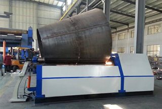
1. Principle of the cone rolling
Cylindrical and conical workpieces can be created by rotating their generatrix, the line that forms the shape, 360 degrees around the centerline of rotation within the same plane.
In the case of a cylindrical workpiece, the generatrix is parallel to the centerline of rotation, while for a conical workpiece, the generatrix is inclined to the centerline of rotation.
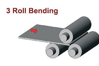
The principle of three-point bending is utilized to roll both cylindrical and conical workpieces.
There are three steps in the rolling process:
1st step:
To begin the roll bending process, feed the workpiece into the work roller of the roll bending machine. The roll bending machine consists of three rolls for a three-roll bending machine or four rolls for a four-roll bending machine.
For a three-roll bending machine, one roll is located above the workpiece and is called the upper roll, while two rolls located under the workpiece are known as the lower rolls.
In a four-roll bending machine, there are three rollers located under the workpiece, with one in the same vertical plane as the upper roller, known as the middle lower roller, and the other two on both sides of the upper roll, called the side rolls.
The upper roller of the roll bending machine can bend the workpiece with any two rollers of the side roller and the middle and lower rollers. This article only covers the symmetrical arrangement of two lower rolls or side rolls and upper rolls.
2nd step:
The second step in the roll bending process is to feed the work roll in a three-point bending motion. In some cases, the upper roll is utilized to press down the feed, while the lower or side roll moves upward.
For descriptive purposes, based on the principle of relative motion, the workpiece and the lower or side roll are considered stationary, and the upper roll is pressed down. When rolling a cylindrical workpiece, the upper roller is parallel to the lower roller as it presses down. When rolling a conical workpiece, the upper roller is inclined to the lower roller during the pressing process.
As the reduction increases, the curvature of the generatrix and its vicinity become greater.
3rd step:
The third step in the roll bending process involves rotating the workpiece through the rotary motion of the work roll. Meanwhile, the reduction of the upper roll is kept constant, resulting in each generatrix of the workpiece having the same curvature or curvature distribution and becoming a circular cylinder or conical cylinder.
There are many methods to roll the cone with the plate rolling machine, each suitable for different workpieces and with their own unique characteristics. Regardless of the method used, it’s important to ensure that the generatrix of the workpiece coincides with that of the upper roll during the rolling process.
The conical cylinder is a fan-shaped steel plate rolled in the plate bending machine of the cylindrical work roll. It’s important to ensure that the generatrix of the workpiece coincides with that of the upper roll during the rolling process.
The motion of the fan-shaped steel plate between the work rolls can be considered as a combined motion of the uniform motion of each point on the workpiece generatrix in the direction perpendicular to the axis of the work roll (the rotary motion of the main transmission device of the cylindrical work roll can achieve this motion) and the rotation of the workpiece around a vertical line passing through a certain point on the generatrix.
To make the big head go faster or the small head slower, an additional moment is applied to the fan-shaped steel plate to overcome the friction between the workpiece and the work roll. This is the key to rolling the cone.
The rotational movement of the workpiece around the vertical line passing through this point on its own generatrix requires the smallest moment.
2. Method of the cone rolling
Depending on whether the thrust roller (block) is used during the rolling process, it can be categorized as either the thrust roller method or the non-thrust roller method.
There are the following types of non-thrust roller methods:
1) Partition marking method:
To execute this method, draw several generatrices on the fan surface of the workpiece. Then, align each generatrix of the workpiece with the generatrix of the upper roll and roll the workpiece on both sides of each generatrix using generatrix partition.
Although simple, this is an approximate and discontinuous method with low efficiency.
The rotation of the fan-shaped steel plate around the plumb line, which passes through a specific point on its generatrix, is achieved by manually aligning the generatrix.
2) Cone roll method:
The cone roll method is used for workpieces with three tapered rollers. The taper of the tapered roller is determined by the workpiece, and there is no sliding between the workpiece and the roller surface.
There are active rolls with tapered rolls (usually upper rolls) and passive rolls with segmented sleeves. The workpiece, the roller sleeve, and the roller core slide against each other. As the number of rolls increases, the sliding between the workpiece and the sleeve decreases.
The movement of a fan-shaped steel plate is accomplished directly through a cone roller. The cone roller method is the most efficient and cost-effective method, suitable for single-variety and mass production.
3) Clamping roll method:
Generally, the clamping roll method is used with a four-roller bending machine. To implement this method, tilt the lower roller, clamp the large end of the workpiece with the upper and lower rollers, and adjust the tilt amount and clamping force of the lower roller to suit various workpieces.
The rotational movement of a fan-shaped steel plate around a vertical line passing through a particular point on its generatrix is accomplished by the friction between the clamping roller and the surface of the workpiece. Although this method is simple, it requires experience, and when the taper is large or the workpiece is thick, it is often used in combination with the thrust roller.
The non-thrust roller method has the advantage that the plate edge of the workpiece does not contact with the thrust roller, and the bevel edge can be made first and then rolled. The integrity of the bevel edge affects the welding quality. The thrust roller method can damage the bevel edge of the workpiece, especially for workpieces with larger or thicker tapers.
However, creating a bevel edge on a circular workpiece after rolling is very challenging. To make the bevel edge first and then roll the cone, the following winding device is designed on a three-roll plate bending machine with a 70 × 3500 active roller as the upper roll of both cylinder and cone.
A cone sleeve made up of three sections is designed for the upper roll of the wind turbine tower based on the tower’s taper. The cone sleeve is firmly connected to the upper roller with a key. The cone sleeve has an average thickness of 35mm and is quenched and tempered. It is dynamically coordinated with the upper roller.
The surfaces of the two lower rollers are quenched, and a small clamping roller driven by an oil cylinder can be placed in the space between the two lower rollers. The clamping roller should clamp the workpiece and the upper roll to prevent the workpiece from sliding with the upper roller. The actual rolling result is a 26mm thick Q345 workpiece. Due to the small taper of the workpiece, a better effect can be achieved without a clamping roller. If the upper roll is also hardened, it will be easier to remove and install the cone sleeve. This is a combination of the cone roller method and the clamping roller method.
As the lower roll is a cylindrical roll and the upper roll is covered with a roller sleeve, the structure is simple and the cost is low. There are several types of thrust roller methods:
1) A thrust roller is set on the upper roll on the overturning side:
The thrust roller is installed in the transition section between the upper roll body and the upper roll overturning side bearing through axial and radial bearings.
A part of the thrust roller is inserted into the overturning frame to limit the thrust roller from rotating with the upper roll.
The thrust roller is generally in contact with the small end plate edge of the workpiece, and the rotational movement of the fan-shaped steel plate around the plumb line passing through a certain point on its own generatrix is realized by the friction force between the thrust roller and the workpiece plate edge.
This method is suitable for the workpiece with a smaller plate thickness, larger taper, and smaller head thrust roller.
2) A thrust roller is set on the lower roll on the overturning side:
The thrust roller is set on the two lower roller bearing blocks on the overturning side, and is directly fixedly connected with the upper part of the lower roll bearing seat.
The working principle is the same as that of the first method, which is suitable for the workpiece with larger taper and smaller head thrust roller, and the plate thickness is larger than that of the first method.
3) A thrust roller is arranged on the frame on the overturned side:
The thrust roller is installed on the frame on the overturned side of the four-roll bending machine with bolts, and the upper plane of the thrust roller is slightly higher than the lower generatrix of the upper roll.
4) A thrust roller is arranged on the overturning frame:
Thrust rollers are installed on both sides of the upper roller and on the overturning frame, with short sliding keys set between the overturning frame and the machine frame.
5) A thrust roller is set on the machine bed:
The thrust roller frame is installed on the bed with a pin, and the thrust roller is installed on both sides of the roller.
The thrust roller frame can rotate around the pin shaft, and the thrust roller can be lifted and lowered within the thrust roller frame.
6) A thrust roller is arranged on the frame at the transmission side:
A large mounting plane is arranged on both sides of the upper roller on the frame on the transmission side.
The plane has optional internal threads, trapezoidal grooves, pin shafts, keys, etc. for fastening the thrust roller device, allowing the gear device’s relative position and direction to the work roll to be changed as required.
All of them are installed on the low side of the frame. Generally, the workpiece will not interfere with it, and the thrust roller is close to the work roll surface.
This method can be used to roll workpieces with a larger taper and a smaller head thrust roller.
3. Methods to improve the ability of cone rolling
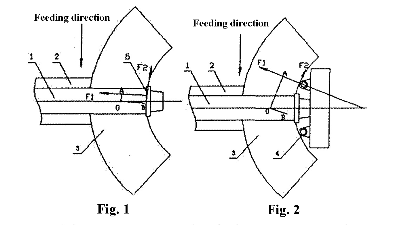
Methods 2, 4, 5, and 6 all utilize two thrust rollers located on both sides of the upper roll.
During operation, the plate is placed against the two thrust rollers, with the feeding side thrust roller exerting torque on the workpiece and the discharge side thrust roller guiding the workpiece.
Under the force of the thrust rollers, the workpiece will deviate from its original position.
Most of the time, the workpiece is in contact with only one gear wheel.
The feeding side thrust roller exerts torque on the workpiece, while the discharge side thrust roller guides the workpiece. If the workpiece rotates too far around the center line, it is blocked back by the thrust roller on the discharge side.
The two thrust rollers work together to guide and apply the rotary moment.
The guiding effect of two thrust rollers is better than that of one, and the rotational torque exerted by two thrust rollers on the workpiece is greater than that of one. However, the two thrust rollers are on both sides of the upper roll.
When the thrust roller of the small head of the workpiece is small, it is not easy to block the workpiece. When two thrust rollers are used, the workpiece is better guided and can move up and down along its own axis. This results in less wear on the plate edge and a longer quenching life of the retaining wheel surface.
When two thrust rollers are used, the contact between the workpiece and the gear wheel creates a more direct and efficient radial force, rather than relying on friction, so there is no need to consider the friction coefficient.
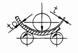
The farther the thrust roller is from the upper roll, the longer the arm of force is, which leads to a greater applied rotating torque. This is illustrated in Fig. 1 and Fig. 2. The thickness of the rolled cone tube also requires a larger thrust roller for the small end of the workpiece.
In method 6, there are bearing blocks at both ends of the thrust roller, making it a simply supported beam with a large bearing capacity. In contrast, in method 5, the retaining wheel is a cantilever beam with a relatively small bearing capacity.
In method 5, the thrust roller is located on the lathe bed, and the workpiece and the frame are less likely to interfere with each other.
We used Method 6 on a 55 × 3200 three-roll bending machine to roll a workpiece with a half cone angle of 30 degrees.
To avoid interference between the workpiece and the wide frame, a 1m high bracket with a large bottom and a small upper part was added between the thrust roller and the mounting plane of the frame, and the stop wheel was inserted into the work roll surface along the axial direction.
Sometimes, when the workpiece is flat and the thrust roller cannot reach it, the problem can be solved by bending the workpiece first or moving the thrust roller downward.
The disadvantage of the thrust roller method is damage to the plate edge at one end of the workpiece.
The thrust roller can rotate around its own axis and move up and down along its own axis, and its surface is quenched to reduce the damage to the plate edge.
Increasing the distance between the thrust roller and the upper roll can not only reduce the force between the thrust roller and the workpiece, but also increase the force on the thick workpiece, which requires pre-bending the longer plate end if possible.
Friction and friction coefficient are very important factors in the process of rolling a cone.
In the case of the non-thrust roller method, a better effect can be achieved without a clamping roller, which may be due to the different friction coefficient between the upper roll and the lower roll.
During the rolling of a 40-50mm thick high-strength steel cone tube for a large-scale project on a 100 × 4000 three-roll plate rolling machine, all the bolts for the gear wheel mounting on the frame at the drive side were cut off, and the project came to a standstill.
According to our field analysis and experience, this may be caused by resonance.
It is suggested to add a little lubricating oil between the workpiece and the passive roller to change the friction coefficient and vibration frequency.
This not only solves the problem but also allows for the rolling of thicker workpieces, as the lubricating oil also reduces the rotary load of the workpiece around the plumb line passing through a point on its generatrix.
It should be noted that the lubricating oil on the workpiece should be removed after coiling to avoid affecting the welding quality.
How much force each method requires for different workpieces depends on both experience and rough calculation.
From the above analysis, it can be seen that there is only one thrust roller to apply the rotary moment to the workpiece, and the load cannot be evenly divided between the two thrust rollers.
A certain unit’s 70 × 3000 plate rolling machine is used to roll 60 × 2000 blast furnace shell cones with method 6. Due to the insufficient strength of the connecting bolts between the upper and lower parts of the transmission side frame, the bolts broke during the rolling process, and the frame connection was improved to successfully complete the rolling.
In method 1, the thrust roller mainly relies on the friction between the thrust roller and the workpiece. The positive pressure on the thrust roller is several times the friction force, and the workpiece is easily damaged during rolling.
Choose the appropriate method based on the size of the workpiece and different requirements.