Plate Rolling Procedure: Step-by-Step Operation Guide
Have you ever wondered how skilled operators bend steel plates into perfect cylinders? In this captivating blog post, we'll take you behind the scenes to explore the art and science…
Have you ever wondered how those massive steel structures are formed into perfect curves? Roll bending is the secret behind it. In this article, we’ll dive into the fascinating world of roll bending, exploring its characteristics, processes, and the machines that make it all possible. Whether you’re an engineering enthusiast or simply curious, join us on this journey to uncover the art and science of shaping steel.
In the production of boilers and pressure vessels, the use of roll bending technology is widespread. It includes cylindrical, conical roll bending, as well as a variety of section steel roll bending, with cylindrical tube section roll bending being the most common.
Sheet metal is used to form these parts and they can be made through pressing or roll bending method, also known as rolling plate. The pressing method typically uses a universal die while a roll bending machine is used to perform continuous three-point bending on the plate, causing plastic deformation to achieve the required bending radius.
Roll bending is a method of bending forming in which a roll bending machine is used to bend a sheet metal or profile blank. The shapes that can be achieved through roll bending include cylindrical, conical, and variable curvature.
For parts with equal thickness and variable thickness in the thickness direction, a three-roll plate bending machine is typically used. Roll bending parts made from profiles, such as angle or T-shaped profiles, can have either equal curvature or variable curvature. The blanks used in roll bending can be either extruded or plate-bending. For bending parts with variable curvature, a four-roll plate bending machine is typically used.
When rolling, the sheet material is positioned between the upper and lower roller shafts of the roller bed. The upper roller shaft then descends, causing the plate material to bend and deform due to the bending moment. The rotation of the upper and lower roller shafts creates friction between the roller shaft and steel plate, which drives the plate to move, continuously changing the pressure position of the sheet metal and forming a smooth bending surface, thus completing the roll forming process.
During roll bending, the sheet metal undergoes equivalent deformation to free bending. The curvature of the roll-bent part is determined by the position of the rollers, the thickness of the sheet metal, and its mechanical properties. By adjusting the relative position between the rollers, the blank can be bent into any curvature smaller than the curvature of the upper roller. However, due to bending elastic recovery, the curvature of the roll-bent part cannot be equal to that of the upper roller.
One of the key advantages of the roll forming method is its versatility. Generally, there’s no need to add any additional process equipment to the plate rolling machine. Only rollers that are suitable for different section shapes and sizes are needed for profile roll bending. However, the method also has some disadvantages, including low productivity and low precision.
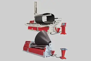
Roll bending machines come in two forms: plate roller and section steel roll bending machine. The majority of materials processed using roll-bending are plate blanks, so the plate roller is primarily used. There are three main types of plate rolling machines: symmetrical three-roll plate roller, asymmetrical three-roll plate roller, and four-roll plate roller.
The primary method of rolling and bending on a plate roller is to roll a cylindrical surface using a plate blank. With the adoption of proper technological measures and necessary equipment, it’s possible to roll conical surfaces and section steel for roll bending as well.
Steel plate rolling consists of three steps: pre-bending (pressing head), centring and rolll bending.
1) Pre-bending
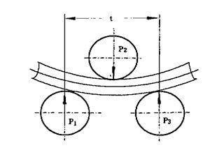
It can be observed from Figure 1 that only a portion of the steel plate that comes in contact with the upper roller shaft can undergo bending. As a result, there will be a length at both ends of the steel plate that cannot be bent. This length is referred to as the residual straight edge.
The size of the residual straight edge is dependent on the bending form of the equipment. The theoretical value of the residual straight edge is shown in Table 1. Typically, the actual residual straight edge is larger than the theoretical value, with values ranging from 6-20t for symmetrical bending and 1/10-1/6 for asymmetrical bending.
Table 1 Theoretical residual straight boundary value of steel plate bending
| Equipment type | Plate rolling machine | Press | |||
|---|---|---|---|---|---|
| Bending form | Symmetrical bending | Asymmetric bending | Die bending | ||
| Three-roll | Four-roll | ||||
| Remaining straight edge | Cold bending | L/2 | (1.5~2 )t | (1~2) t | 1.0 t |
| Hot bending | L/2 | (1.3~1.5) t | (0.75~1) t | 0.5 t | |
Note: in the table, L is the center distance of side roll of plate bending machine, and t is thickness of steel plate.
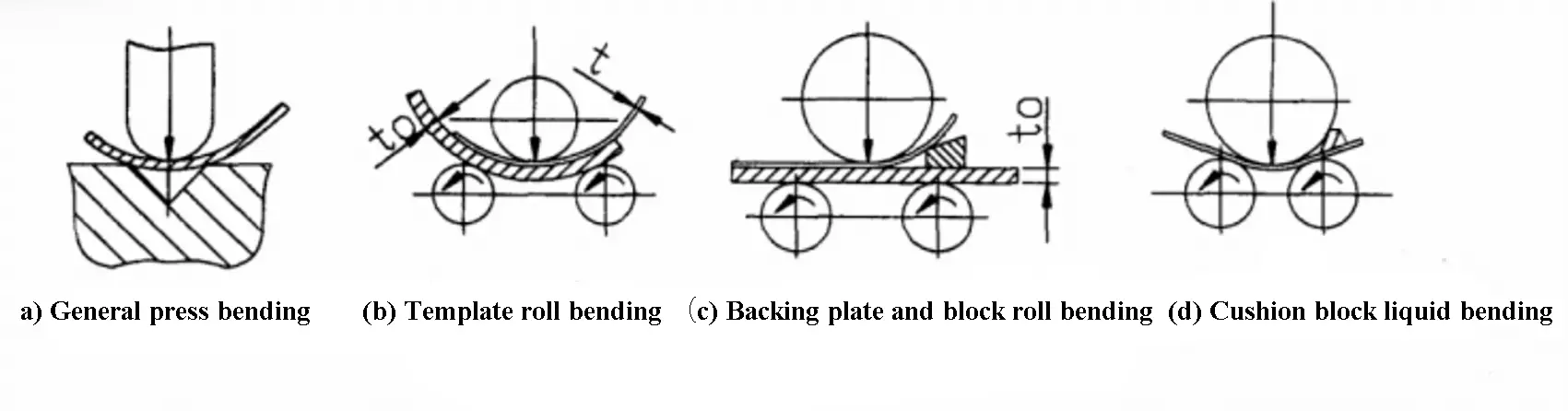
It is shown in Fig. 1 (a).
This method is suitable for pre-bending of various thickness steel plates.
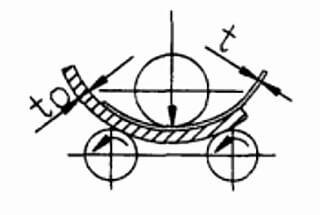
It is shown in Fig. 1 (b).
This method is suitable for t≤t0/2, t≤24mm, which does not exceed 60% of the equipment capacity.
As shown in Fig. 1 (c).
This method is suitable for t≤t0/2, t≤24 mm, which does not exceed 60% of the equipment capacity.
It is shown in Fig. 1 (d).
This method is suitable for thin steel plate, but its operation is more complicated and is rarely used.
2) Centering
The purpose of centering is to align the centerline of the workpiece parallel to the roll axis, eliminate the possibility of torsion, and maintain the accurate geometric shape of the workpiece after roll bending.
Centering techniques include: side roll centering, special baffle centering, inclined feed centering, and side roll slotting centering, as depicted in Figure 2.

3) Roll bending
Rolling bending of steel plate is usually carried out on a rolling machine.
The typical rolling parts are cylindrical and conical.
a. Roll bending for cylindrical parts
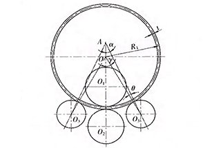
When bending the cylinder on a symmetrical three roll bending machine, the position of the upper roll shaft during final bending can be determined according to the known bending radius, as shown in Fig. 3 (a).

Where:
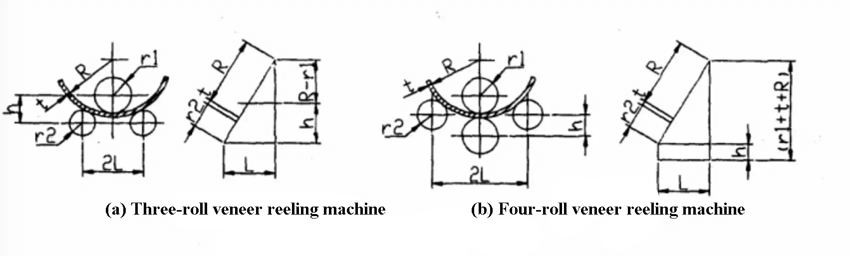
The final bending position of the side roll shaft is shown in Fig. 3 (b) when the cylindrical surface is rolled on a four-roll plate bending machine, which can be obtained by the following formula:
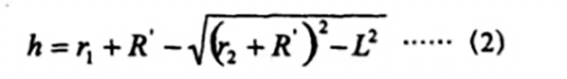
Where:
Due to the springback of sheet metal, the value of H obtained in the above formula needs to be corrected properly in practical application.
b. Roll bending of conical surface:
The commonly used cone roll bending methods are the small mouth deceleration method, double speed four roll bending method, rotary feeding method, and zone rolling bending method.
This is due to the fact that the surface prime lines on the cone are not parallel and the curvature of each point on the prime line is unique.
To ensure that the upper roller is pressing on the centerline of the cone at all times during the bending process and to produce different curvature radii along the centerline, the following measures should be taken:
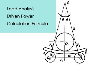
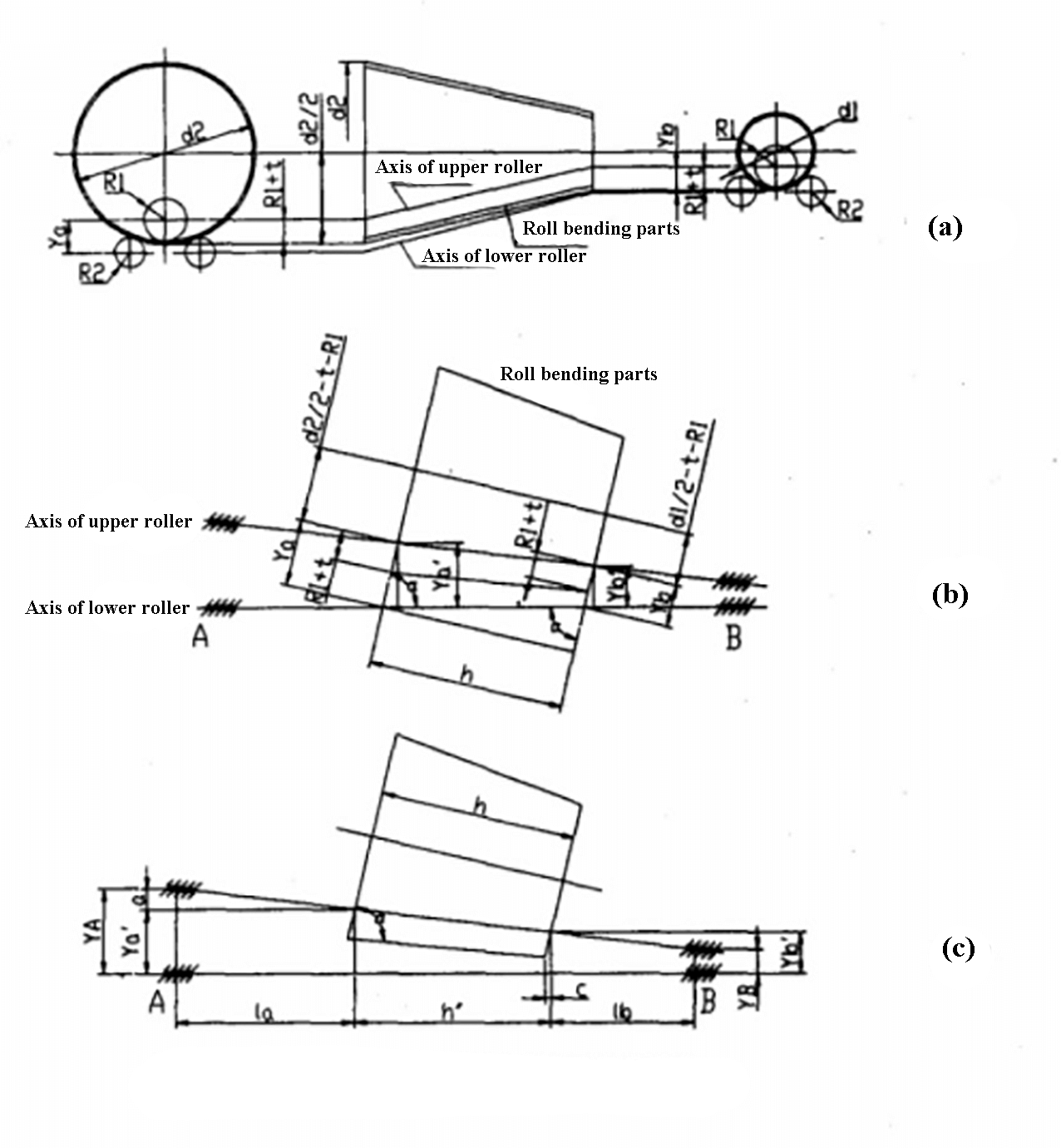
For conical parts with a large taper, the vertical center distances, Ya and Yb, of both the upper and lower rollers at both ends can be calculated using the geometric figure shown in Figure 4.
The center distances, Ya and Yb, of the upper and lower rollers can be obtained by applying the calculation method for circular simple parts, i.e. using formula (1).
From the geometric figures shown in Figures 4 (b) and 4 (c), the following values can be obtained:
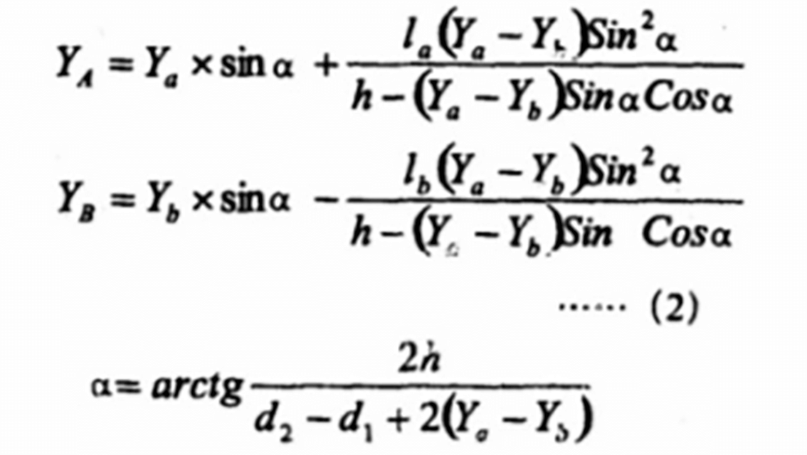
The position of the blank from the right end of the roller is determined by lb+c, where

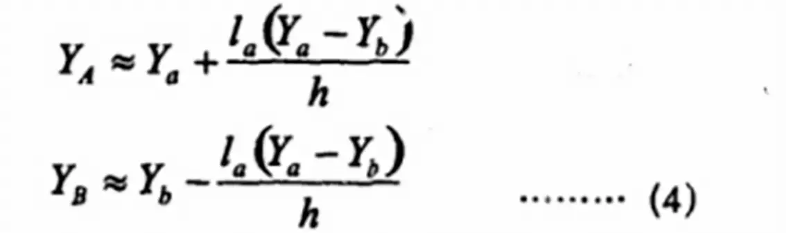
For conical parts with small taper, equation (2) can be simplified as follows:
When rolling conical parts, it’s common to experience distortion.
An effective method to eliminate this distortion is to incline the upper roller reasonably and maintain the parallel alignment of the lower roller.
During the rolling and bending process, the blank is formed through a series of overlapping sectional roll bendings.
According to the different temperatures of the rolling plate, it can be divided into cold rolling, hot rolling and medium rolling.
1) Cold rolling
Rolling a plate at normal temperature, also known as cold rolling, is appropriate for rolling thin to medium thickness plates.
However, it results in a certain amount of springback, as demonstrated in Figure 5.
Once the desired bending has been achieved, it’s necessary to roll back several times to fix the curvature.
High strength steel exhibits a large degree of springback. To reduce springback, it’s advisable to perform annealing treatment prior to the final forming process.
The minimum diameter of a cylinder that can be bent using the bending machine is dependent on the diameter of the upper roll.
Taking into account the springback of the cylinder after bending, the minimum diameter of a bendable cylinder is approximately 1.1 to 1.2 times the diameter of the upper roll.
Cold rolling is a convenient process with easy-to-control curvatures and low production costs. However, it requires powerful equipment for thicker plates and is susceptible to the development of cold work hardening.
2) Hot rolling
It is generally considered that when the thickness (t) of a carbon steel plate is greater than or equal to one-fortieth of the inner diameter (D) (t ≥ 1/40 D), hot rolling should be carried out. (Note: according to this simple formula and the calculation method of fiber elongation, the difference between cold and hot thickness is large.)
During heat bending, the sheet metal should be heated to 950 to 1100 ℃, with uniform heating and rapid operation. The final temperature should not be lower than 700 ℃.
Hot rolling eliminates the need to consider springback, and for a closed cylinder, roll bending can be performed until the longitudinal seam is just closed. To prevent the workpiece from being removed from the plate too early during hot rolling, it should be continuously rolled at the final bending rate until the surface color turns dark.
When the workpiece is in a cold state, it should be placed as shown in Figure 6, or it can be placed vertically. Hot rolling can prevent cold work hardening of the material and reduce the power required by the bending machine.
However, there are also drawbacks to hot rolling: if the operation is difficult, heating the steel plate to a high temperature can cause serious oxidation.
3) Warm rolling
When the plate is heated to a temperature range of 500 to 600 degrees Celsius for rolling, it is referred to as warm rolling. Compared to cold rolling, warm rolling has better plasticity and reduces the risk of brittle fracture and the stress on the bending machine. Additionally, compared to hot rolling, warm rolling reduces the surface defects caused by oxide scale and improves operating conditions.
However, warm rolling also has its disadvantages, as it can cause internal stress due to rolling, which may require heat treatment for stress relief based on the product requirements. Although the heating temperature of warm rolling is below the recrystallization temperature of the metal, it still falls within the realm of cold working.
Bending in one operation is not possible with warm rolling, as multiple cold roll bendings can cause cold work hardening of the material. When the bending deformation is substantial, the cold work hardening phenomenon will become very pronounced, leading to a serious deterioration in the service performance of the bent parts.
As a result, the allowed bending radius for cold rolling forming should be larger than the minimum bending radius of sheet metal, with R = 20t (where t is the plate thickness). When R is less than 20t, hot roll bending should be carried out.

For parts with a small bending radius, manual sizing may be necessary after roll bending. It is important to reserve a reasonable sizing allowance, meaning each side should be slightly smaller than the template or card plate, with a difference of 2 to 4mm (as shown in Fig. 7).
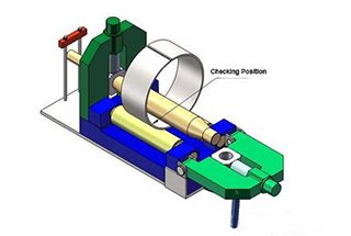
For roll bending parts with a relatively large bending radius, the curvature must be inspected according to the shape inspection standard to ensure that the parts can fit the card plate under a certain external force (P).
The capacity of the bending machine can be converted to expand its scope of use.
As shown in Figure 8, the conversion formula is as follows:
3.1 The plate width required by the rolling material is the same as that required by the rolling machine specification, but the bending radius is different.
Where:
3.2 The rolling material is the same as the diameter required by the specification of the plate bending machine, but the plate width is different, and the rolling is symmetrical, that is, a1=c1,a2=c2
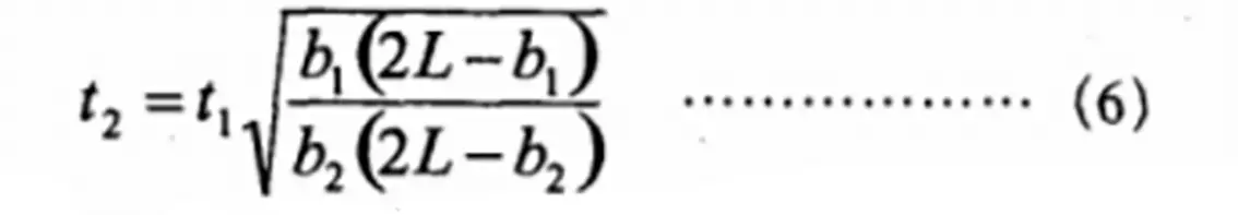
Where:
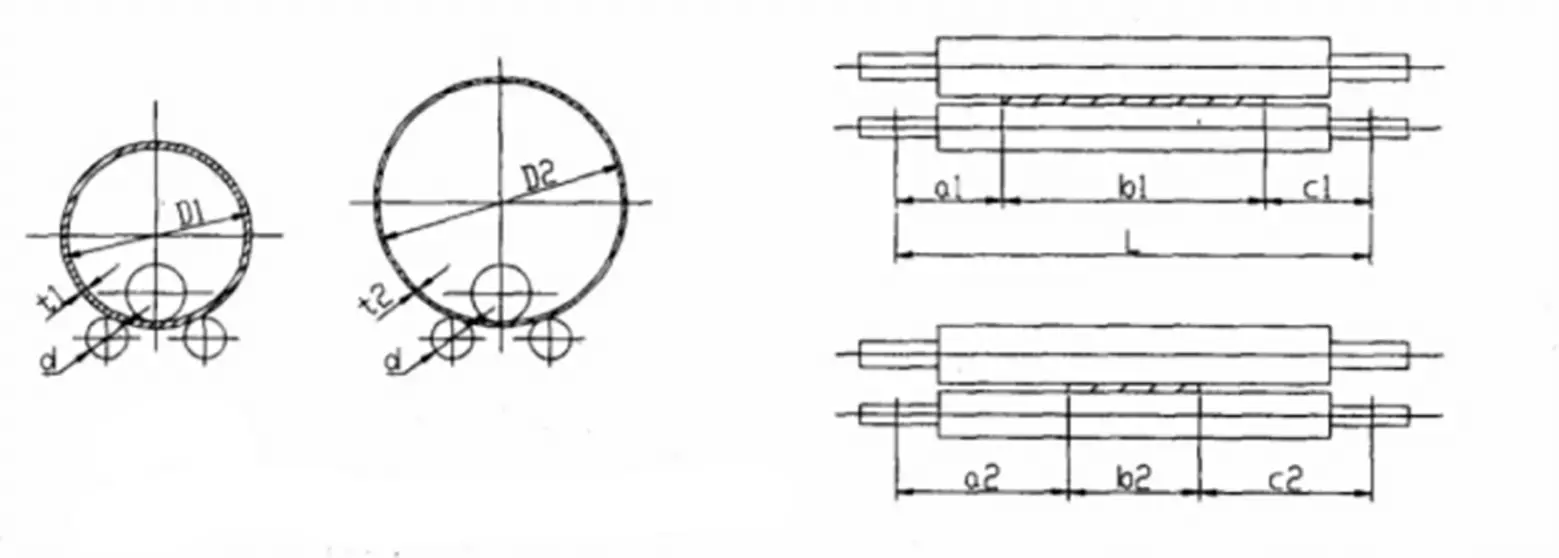
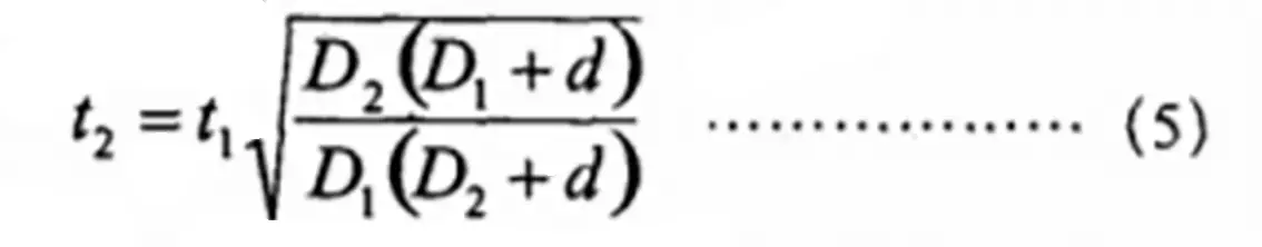
3.3 The roll bending diameter is the same as the plate width required by the specification of the bending machine, but the material is different.
Where
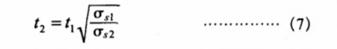
3.4 The rolling diameter, plate width and material are the same, and the rolling temperature is different.
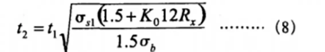
Where
The roll bending technology is widely used in production and has higher demands for the surface quality of roll-bent parts due to the use of materials such as stainless steel, aluminum, and composite steel plates. Annealing treatment before roll bending is now necessary for steel grades that are sensitive to hardenability.
To ensure the quality of roll bending meets the requirements, it is essential to carry out a reasonable calculation and selection of roll bending equipment and analyze the measures taken.
With the analysis, calculation, and application of the roll bending process, various specifications of curved surface bending can be achieved on the bending machine, thereby enhancing the utilization of the equipment.

As the founder of MachineMFG, I have dedicated over a decade of my career to the metalworking industry. My extensive experience has allowed me to become an expert in the fields of sheet metal fabrication, machining, mechanical engineering, and machine tools for metals. I am constantly thinking, reading, and writing about these subjects, constantly striving to stay at the forefront of my field. Let my knowledge and expertise be an asset to your business.